Cross reference to related application
This Application is a 371 of PCT/JP2013/082097 filed on Nov. 28, 2013 which, in turn, claimed the priority of Japanese Patent Application No. JP2012-260040 filed on Nov. 28, 2012, both applications are incorporated herein by reference.
Technical field
The present invention relates to a transparent electrode, and an electronic device, particularly relates to a transparent electrode having both electrical conductivity and light transmission property, and to an electronic device using the transparent electrode.
Background art
An organic electroluminescent element (hereinafter, referred to as “organic EL element”) utilizing electroluminescence (hereinafter, referred to as “EL”) of an organic material is a thin-film type completely-solid state element capable of emitting light at a low voltage of several volts to several ten volts, and has many excellent features such as high luminance, high light emission efficiency, small thickness and light weight. Accordingly, in recent years, the element has attracted attention, as backlights for various kinds of displays, display boards such as a signboard and an emergency lamp, and surface emitting bodies such as illumination light sources.
Such an organic electroluminescent element has a configuration obtained by holding a light-emitting layer formed of an organic material between two electrodes, the emitted light generated in the light-emitting layer is extracted to the outside through the electrode. Therefore, at least one of the two electrodes is constituted as a transparent electrode.
As the transparent electrode, there is used generally a material of an oxide semiconductor type such as indium tin oxide (SnO2-In2O3:Indium Tin Oxide:ITO), and examination aiming at lowering electric resistance by laminating ITO and silver has been carried out (e.g. referring to the following Patent Literatures 1, 2). In addition, ITO has a high raw cost because of using a rare metal indium, and is required to be subjected to annealing treatment at about 300° C. after the formation in order to lower its electric resistance. Accordingly, there have been proposed a configuration in which a metallic material such as silver having a high electrical conductivity is made into a thin film, and a configuration in which an electrical conductivity is ensured even at a film thickness smaller than that of silver alone by blending aluminum with silver (e.g. refer to the following Patent Literature 3). CITATION LIST Patent Literature
PTL 1: Japanese Patent Laid-Open No. 2002-15623
PTL 2: Japanese Patent Laid-Open No. 2006-164961
PTL 3: Japanese Patent Laid-Open No. 2009-151963 SUMMARY OF INVENTION Technical Problem
However, even by using the transparent electrode constituted using silver and aluminum with a high electrical conductivity, it has been difficult to attain sufficient electrical conductivity and light transmission property, at the same time.
In order to solve the above-described problems, the present invention provides a transparent electrode excellent in both electrical conductivity and light transmission property, and an electronic device. Solution to Problem
The transparent electrode of the present invention includes a nitrogen-containing layer, a conductive layer provided adjacent to the nitrogen-containing layer and having silver as a main component, a high refractive index layer provided to sandwich the nitrogen-containing layer between the conductive layer and the high refractive index layer and having a higher refractive index than that of the nitrogen-containing layer, and a low refractive index layer provided in contact with the high refractive index layer and having a lower refractive index than that of the high refractive index layer. The nitrogen-containing layer is constituted using a compound which contains nitrogen atoms, and has an effective unshared electron pair content [n/M] of 2.0×10.sup.−3≦[n/M], when n is the number of unshared electron pairs which are not involved in aromaticity and which are not coordinated to a metal in the unshared electron pairs of the nitrogen atoms, and M is a molecular weight.
In addition, the electronic device of the present invention includes the above-described transparent electrode.
According to the transparent electrode of the present invention, the conductive layer containing silver as a main component is provided adjacent to the nitrogen-containing layer constituted using the compound including a nitrogen atom. The nitrogen-containing layer is constituted of the compound having an effective unshared electron pair content [n/M] of 2.0×10.sup.−3≦[n/M]. Furthermore, the transparent electrode of the present invention has the high refractive index layer and the low refractive index layer.
By the formation of the conductive layer containing silver as a main component on the above-described nitrogen-containing layer, the agglomeration of the silver is suppressed due to interaction of the silver atom and the compound constituting the nitrogen-containing layer, and thus the conductive layer having a uniform thickness was obtained although the thickness is small. The reflection caused on the conductive layer containing silver as a main component is suppressed by laminating the low refractive index layer, the high refractive index layer, the nitrogen-containing layer and the conductive layer in this order.
Accordingly, in the transparent electrode using silver, it becomes possible to enhance both of electrical conductivity and light transmission property. In addition, the electronic device excellent in electrical conductivity and light transmission property can be constituted by using the transparent electrode. Advantageous Effects of Invention
According to the present invention, the transparent electrode and the electronic device being excellent in electrical conductivity and light transmission property can be provided.
Brief description of drawings
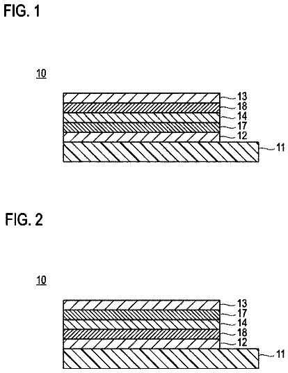
FIG. 1 is a cross-sectional view of a configuration of an embodiment of a transparent electrode.
FIG. 2 is a drawing showing structural formulae of TBAC and Ir(ppy).sub.3 for explaining the manner of bonding of a nitrogen atom.
FIG. 3 is a drawing showing a structural formula and molecular orbital of a pyridine ring.
FIG. 4 is a drawing showing a structural formula and molecular orbital of a pyrrole ring.
FIG. 5 is a drawing showing a structural formula and molecular orbital of an imidazole ring.
FIG. 6 is a drawing showing a structural formula and molecular orbital of a δ-carboline ring.
FIG. 7 is a cross-sectional view showing a configuration of an organic electroluminescent element of the embodiment.
FIG. 8 is a cross-sectional view showing the configuration of the organic electroluminescent element of the embodiment.
FIG. 9 is a cross-sectional view showing the configuration of the organic electroluminescent element of an Example.
Description of embodiments
Hereinafter, the embodiments according to the present invention will be explained by referring drawings in the order mentioned below.
1. Transparent electrode
2. A first embodiment of organic electroluminescent element (bottom emission type)
3. A second embodiment of organic electroluminescent element (reverse laminate configuration)
4. Lighting device
Note that, in each embodiment, the same symbol is attached to the common constituent element, and an overlapped explanation will be omitted.
<1. Transparent Electrode>
Hereinafter, the specific embodiment of the transparent electrode of the present invention will be explained.
In FIG. 1 , the schematic configuration diagram (cross-sectional view) of the transparent electrode of the present embodiment is shown. AS shown in FIG. 1 , a transparent electrode 10 includes a low refractive index layer 12 , a high refractive index layer 13 , a nitrogen-containing layer 14 and a conductive layer 15 . The conductive layer 15 is formed adjacent to the nitrogen-containing layer 14 . The nitrogen-containing layer 14 is sandwiched between the conductive layer 15 and the high refractive index layer 13 . One surface of the high refractive index layer 13 is in contact with the nitrogen-containing layer 14 , and the low refractive index layer 12 is formed in contact with the other surface.
The lamination structure constituted of the low refractive index layer 12 , the high refractive index layer 13 , the nitrogen-containing layer 14 and the conductive layer 15 I provided on a base material 11 .
In the above construction, the high refractive index layer 13 is a layer having a refractive index higher than that of the nitrogen-containing layer 14 . In addition, the low refractive index layer 12 is a layer having a refractive index lower than the high refractive index layer 13 . The conductive layer 15 constituting an electrode part of the transparent electrode 10 is a layer constituted using silver (Ag) as a main component. The nitrogen-containing layer 14 adjacent to the conductive layer 15 is constituted using a compound which contains a nitrogen atom (N). Particularly, the nitrogen-containing layer 14 is constituted of a compound in which a content of an unshared electron pair (effective unshared electron pair) of a nitrogen atom stably bonding to the silver being a main material of the conductive layer 15 is within a predetermined range.
Hereinafter, as to the transparent electrode 10 of the example, a detailed configuration will be explained in order of the base material 11 , the low refractive index layer 12 , the high refractive index layer 13 , the nitrogen-containing layer 14 , and the conductive layer 15 . Note that, in the transparent electrode 10 of the example, translucency means that light transmittance at a wavelength of 550 nm is 50% or more.
[Base Material 11 ]
The base material 11 on which the transparent electrode 10 is formed includes, for example, glass, plastics, or the like, but is not limited to these. In addition, the base material 11 may be transparent or opaque. When the transparent electrode 10 is used as an electronic device in which light is taken out from the side of the base material 11 , the base material 11 is preferably transparent. Preferably used transparent base material 11 can include glass, quartz, and transparent resin film. When the transparent electrode 10 is used for an electronic device in which light is taken out from the opposite side of the base material 11 , the base material 11 may be transparent or opaque.
[Glass]
Examples of the glasses include silica glass, soda lime silica glass, lead glass, borosilicate glass, alkali-free glass, and the like. From the viewpoint of a close adhesive characteristic to the laminate structure of the transparent electrode 10 , durability and smoothness, a physical treatment such as polishing may be given as necessary, or a film made of an inorganic material or an organic material, or a hybrid film obtained by combining these coating films may be formed on the surfaces of these glass materials.
Examples of the resin film include polyesters such as polyethylene terephthalate (PET) and polyethylene naphthalate (PEN), polyethylene, polypropylene, cellulose esters or derivative thereof such as cellophane, cellulose diacetate, cellulose triacetate (TAC), cellulose acetate butylate, cellulose acetate propionate (CAP), cellulose acetate phthalate and cellulose nitrate, polyvinylidene chloride, polyvinyl alcohol, polyethylene vinyl alcohol, syndiotactic polystyrene, polycarbonate, norbornen resin, polymethylpenten, polyether ketone, polyimide, polyether sulphone (PES), polyphenylene sulfide, polysluphones, polyether imide, polyether ketone imide, polyamide, fluororesin, Nylon, polymethyl methacrylate, acryl or polyallylates, cycloolefin-based resins such as Alton (commercial name of JSR) or APEL (commercial name of Mitsui Chemicals), and the like.
A coating film made of inorganic materials or organic materials, or a hybrid coating film obtained by combining those coating films may be formed on the surface of the resin film. These coating films or hybrid coating films are preferably a barrier film (also referred to as barrier membrane, or the like) having a water vapor transmittance (25±0.5° C., relative humidity 90±2% RH) measured by the method in accordance with JIS-K-7129-1992 of 0.01 g/(m.sup.2.Math.24 hrs) or less. Furthermore, these films are preferably a high barrier film having an oxygen transmittance measured by the method in accordance with JIS-K-7126-1987 of 10.sup.−3 ml/(m.sup.2.Math.24 hrs.Math.atm) or less and a water vapor transmittance of 10.sup.−5 g/(m.sup.2.Math.24 hrs) or less.
A material for forming the above barrier film may be a material having a function of suppressing penetration of substances such as water vapor and oxygen which deteriorate the resin film. For example, there can be used silicon oxide, silicon dioxide, silicon nitride, and the like. Furthermore, in order to improve fragility of the barrier film, it is more preferably to give a lamination structure of the inorganic layer and a layer of organic material (organic layer). The order of lamination of the inorganic layer and the organic layer is not particularly limited, and is preferable to alternately laminate both of the layers a plurality of times.
The method of forming the barrier film is not particularly limited, and there can be used, for example, vacuum deposition method, spattering method, reactive spattering method, molecular beam epitaxial method, cluster ion beam method, ion platting method, plasma polymerization method, atmospheric pressure plasma polymerization method, plasma CVD method, laser CVD method, thermal CVD method, coating method, and the like. Particularly preferable is the atmospheric pressure plasma polymerization method described in Japanese Patent Application Laid-Open Publication No. 2004-68143.
In contrast, when the base material 11 is opaque, there can be used, for example, a metal substrate such as aluminum or stainless steel, an opaque resin substrate, a substrate made of ceramics, and the like. These substrates may be a film-like substrate which can be bended flexibly.
[Low Refractive Index Layer]
The low refractive index layer 12 is a layer having a refractive index lower than the high refractive index layer 13 in contact with the low refractive index layer 12 . Particularly, a refractive index at a wavelength of 550 nm is preferably lower than the high refractive index layer by 0.1 or more, particularly preferably lower than the high refractive index layer 13 by 0.3 or more. The low refractive index layer 12 as described above is constituted of a material having a low refractive index and a light transmittance property. For example, there can be used a low refractive index material generally used for an optical film such as magnesium fluoride (MgF.sub.2: n=1.37), lithium fluoride (LiF: n=1.39), Calcium fluoride (CaF.sub.2: n=1.43), or aluminum fluoride (AlF.sub.3: n=1.38); a polymeric material such as Poly(1,1,1,3,3,3-hexafluoroisopropyl acrylate): n=1.38, Poly(2,2,3,3,4,4,4-heptafluorobutyl acrylate): n=1.38, Poly(2,2,3,3,4,4,4-heptafluorobutyl methacrylate): n=1.38, Poly(2,2,3,3,3-pentafluoropropyl acrylate): n=1.39, Poly(1,1,1,3,3,3-hexafluoroisopropyl methacrylate): n=1.39, Poly(2,2,3,4,4,4-hexafluorobutyl acrylate): n=1.39, Poly(2,2,3,3,3-pentafluoropropyl methacrylate): n=1.40, Poly(2,2,2-trifluoroethyl acrylate): n=1.41, Poly(2,2,3,3-tetrafluoropropyl acrylate): n=1.42, Poly(2,2,3,3-tetrafluoropropyl methacrylate): n=1.42, or Poly(2,2,2-trifluoroethyl methacrylate): n=1.42; and the like.
In addition, as is shown in FIG. 1 , when the low refractive index layer 12 and the high refractive index layer 13 are laminated on the base material 11 , the low refractive index layer 12 is set to be a layer having a refractive index lower than the high refractive index layer 13 and the base material 11 . At this time, the base material 11 is constituted of a material having a refractive index lower than the high refractive index layer 13 , and the low refractive index layer 12 is set to be a layer having a refractive index lower than the base material 11 . Preferably, a refractive index at a wavelength of 550 nm of the low refractive index layer 12 is preferably lower than the base material 11 by 0.1 or more. Thereby, the transmittance of the transparent electrode 10 can be further enhanced.
Note that, when the refractive index of the base material 11 is lower than the high refractive index layer 13 , the base material 11 may be a low refractive index layer 12 by forming the high refractive index layer 13 directly on the base material 11 , without separately providing the low refractive index layer 12 . Therefore, the configuration may be such that there is employed the lamination structure formed of the high refractive index layer 13 , the nitrogen-containing layer 14 and the conductive layer 15 is provided on the base material by using the base material 11 itself as a low refractive index layer. Alternatively, in the case where the low refractive index layer 12 has a property required for the base material, the low refractive index layer 12 can be used as the base material without separately preparing the base material.
[High Refractive Layer]
The high refractive layer 13 has a refractive index higher than the nitrogen-containing layer 14 . It is preferable that the refractive index of the high refractive layer 13 at a wavelength of 550 nm is higher than a refractive index of the nitrogen-containing layer 14 (n=1.7 to 1.8) by 0.1 or more, more preferable by 0.3 or more. The high refractive layer 13 is constituted by the materials having a high refractive index and light transmission property. Examples include high refractive materials which are generally used for optical films such as titanium oxide (TiO.sub.2: n=2.3 to 2.4), zirconium oxide (ZrO: n=2.4), cadmium oxide (CdO: n=2.49), indium tin oxide (ITO: n=2.1 to 2.2), hafnium oxide (HfO.sub.2: n=1.9 to 2.1), tantalum pentoxide (Ta.sub.2O.sub.5: n=2.16), niobium oxide (Nb.sub.2O.sub.5: n=2.2 to 2.4), and the like.
[Nitrogen-Containing Layer]
The nitrogen-containing layer 14 is formed adjacent to the conductive layer 15 and is a layer sandwiched between the high refractive index layer 13 and the conductive layer 15 .
As the result of the formation of the nitrogen-containing layer 14 in contact with the conductive layer 15 , diffusion distance of silver atoms at the surface of the nitrogen-containing layer is reduced due to the interaction between silver being the principal component of the conductive layer 15 and a compound containing a nitrogen atom constituting the nitrogen-containing layer 14 , and thus aggregation of the silver is suppressed. Therefore, generally, a thin silver layer that tends to be easily isolated in an island shape as the result of the growth by a nuclear growth-type (Volumer-Weber: VW type) is formed by the growth of a single layer growth type (Frank-van der Merwe: FM type). Accordingly, the conductive layer 15 having a uniform thickness, although the thickness is small, can be obtained by forming the conductive layer 15 containing silver as the principal component in contact with the nitrogen-containing layer 14 .
The nitrogen-containing layer 14 preferably has the thickness of 5 nm or less. This is because a smaller thickness of the nitrogen-containing layer 14 , that is, a smaller distance between the high refractive index layer 13 and the conductive layer 15 gives higher light transmittance of the transparent electrode 10 . Note that the thickness of the nitrogen-containing layer 14 is set to be a thickness that does not prevent the FM type growth of the conductive layer 15 formed on the nitrogen-containing layer 14 , that is, to be approximately a thickness of the extent that the nitrogen-containing layer 14 is formed not in an island shape but as a continuous layer covering the high refractive index layer 13 .
Furthermore, the nitrogen-containing layer 14 is a layer provided adjacent to the conductive layer 15 , and is constituted using a compound containing a nitrogen atom (N). An unshared electron pair of a nitrogen atom that is bonded stably to silver being the main material for constituting the conductive layer 15 in the compound containing a nitrogen atom is referred to as an “effective unshared electron pair.” Additionally, the compound constituting the nitrogen-containing layer 14 is characterized in that the content ratio of the effective unshared electron pair” is within a prescribed range.
Here, the “effective unshared electron pair” is defined as an unshared electron pair that is not involved in aromaticity and is not coordinated to a metal, among unshared electron pairs of a nitrogen atom contained in a compound. The aromaticity means an unsaturated ring structure in which atoms having a it electron are arranged in a ring shape, and the aromaticity follows the so-called “Huckel's rule” which requires a condition in which the number of electrons contained in the π electron system on the ring is “4n+2” (n=0, or a natural number).
The “effective unshared electron pair” is selected based on whether or not the unshared electron pair of a nitrogen atom is involved in the aromaticity irrespective of whether or not the nitrogen atom itself including the unshared electron pair is a hetero atom constituting the aromatic ring. For example, even if a certain nitrogen atom is a hetero atom constituting an aromatic ring, when the nitrogen atom has an unshared electron pair that is not directly involved in the aromaticity as the essential element, the unshared electron pair is counted as one of the “effective unshared electron pair.” Namely, if there is an unshared electron pair which is not involved in aromaticity expression as the essential element in the delocalized π electron system in the conjugated unsaturated ring structure (aromatic ring), the unshared electron pair is counted as one of the “effective unshared electron pair.” In contrast, even in the case where a certain nitrogen atom is not a hetero atom constituting an aromatic ring, if all the unshared electron pairs of the nitrogen atom are involved in the aromaticity, the unshared electron pairs of the nitrogen atom are not the “effective unshared electron pair.” Note that, in respective compounds, the number of the “effective unshared electron pair” n coincides with the number of the nitrogen atoms having the “effective unshared electron pair.”
Next, the above-described “effective unshared electron pair” will be explained in detail by referring specific examples.
A nitrogen atom is an element of the group 15 and has 5 electrons on the outermost shell. Among them, three unpaired electrons are used for covalent bond with the other atoms, and the remaining two electrons serve as one pair of unshared electron pair. Therefore, usually, the number of bonds of nitrogen atom is 3.
Examples of the group having a nitrogen atom includes an amino group (—NR.sup.1R.sup.2), an amide group (—C(═O)NR.sup.1R.sup.2), nitro group (—NO.sub.2), cyano group (—CN), diazo group (—N.sub.2), azide group (—N.sub.3), an urea group (—NR.sup.1C═ONR.sup.2—), isothiocyanate group (—N═C═S), a thioamide group (—C(═S)NR.sup.1R.sup.2), and the like. Note that R1 and R2 are each a hydrogen atom (H) or a substituent. The unshared electron pair of the nitrogen atom constituting these groups corresponds to [effective unshared electron pair] since the pair is not involved in aromatibity and does not coordinate with a metal. Among them, although the unshared electron pair of the nitrogen atom of nitro group (—NO.sub.2) is utilized for resonance structure with oxygen atom, it is considered that the pair exists on the nitrogen atom as the [effective unshared electron pair] which is not involved in aromaticity and does not coordinate with a metal, since the good results are obtained as shown in the following examples.
Furthermore, the nitrogen atom can produce the fourth bond by utilizing the unshared electron pair. One example of such a case will be explained by referring FIG. 2 . FIG. 2 shows the structural formulae of tetrabutylammonium chloride (TBAC), and tris(2-phenylpyridine)iridium (III) [Ir(ppy).sub.3].
Among them, TBAC is a quaternary ammonium salt where one of four butyl groups ionically bonds to a nitrogen atom and has a chloride ion as a counter ion. In this case, one of the electrons constituting the unshared electron pair of a nitrogen atom is donated to the ionic bond with the butyl group. Therefore, the nitrogen atom of TBAC is equal to a state where an unshared electron pair does not exist initially. Accordingly, the unshared electron pair of the nitrogen constituting TBAC does not correspond to the “effective unshared electron pair” which is not involved in aromaticity and is not coordinated to a metal.
Further, Ir(ppy).sub.3 is a neutral metal complex in which the iridium atom and the nitrogen atom are coordinately bonded. The unshared electron pair of the nitrogen atom constituting Ir(ppy).sub.3 is coordinated to the iridium atom, and is utilized for coordinate bonding. Accordingly, the unshared electron pair of the nitrogen constituting Ir(ppy).sub.3 does not correspond to the “effective unshared electron pair” which is not involved in aromaticity and is not coordinated to a metal.
Nitrogen atom is a usual hetero atom that can constitute an aromatic ring, and can contribute to expression of aromaticity. Examples of the “nitrogen-containing aromatic ring” include pyridine ring, piperazine ring, pyrimidine ring, triazine ring, pyrrole ring, imidazole ring, pyrazole ring, triazole ting, tetrazole ring, and the like.
FIG. 3 shows the structural formula and the molecular orbital of the pyridine ring which is one of the above-described nitrogen-containing aromatic rings. AS shown in FIG. 3 , the pyridine ring has 6 delocalized π electrons in the conjugated (resonant) unsaturated ring structure arranged in the form of a 6-membered ring, and thus satisfies 4n+2 (n=0 or natural numeral) of the “Hueckel's rule”. Since the nitrogen atom in the 6-membered ring is the substituent of —CH═, only one unshared electron is used for the 6 π electron system, and the unshared electron pair is not involved in expression of aromaticity as an essential element.
Accordingly, the unshared electron pair of the nitrogen atom constituting the pyridine ring corresponds to the [effective unshared electron pair] which is not involved in aromaticity and is not coordinated to a metal.
FIG. 4 shows the structural formula and the molecular orbital of the pyrrole ring. AS shown in FIG. 4 , the pyrrole ring has a structure in which one of the carbon atoms constituting five-membered ring is substituted with a nitrogen atom, and since the number of π electrons is six, the pyrrole ring is a nitrogen-containing aromatic ring which satisfies the “Hueckel's rule”. Since the nitrogen atom of the pyrrole ring also bonds to a hydrogen atom, the unshared electron pair is used for the 6 π electron system.
Accordingly, though the nitrogen atom of the pyrrole ring has an unshared electron pair, the unshared electron pair is utilized for expressing the aromaticity as the essential element, and thus does not correspond to the “effective unshared electron pair” which is not involved in aromaticity and is not coordinated to a metal.
FIG. 5 shows the structural formula and the molecular orbital of the imidazole ring. As shown in FIG. 5 , the imidazole ring has a structure in which the carbon atoms of 1-position and 3-position of the five-membered ring are substituted by the two nitrogen atoms N.sup.1, N.sup.2, and is also a nitrogen-containing aromatic ring having six π electrons. Among them, one nitrogen atom N.sup.1 supplies only one unshared electron to the 6 π electron system, and thus, is the nitrogen atom of the pyridine ring-type nitrogen atom in which the unshared electron pair is not utilized for the expression of aromaticity. Accordingly, the unshared electron pair of the nitrogen atom N.sup.1 corresponds to the [effective unshared electron pair]. In contrast to this, since the other nitrogen atom N.sup.2 is the pyrrole ring-type nitrogen atom which supplies the unshared electron pair to the 6 π electron system, the unshared electron pair of the nitrogen atom N.sup.2 does not correspond to the “effective unshared electron pair”.
Accordingly, in the imidazole ring, among the two nitrogen atoms N.sup.1, N.sup.2, only the unshared electron pair of the nitrogen atom N.sup.1 corresponds to the [effective unshared electron pair].
The selection of the unshared electron pair in the nitrogen atom of the “nitrogen-containing aromatic ring” as mentioned above also applies to the case of a condensed ring compound having a nitrogen-containing aromatic ring structure in the same way.
FIG. 6 shows the structural formula and the molecular orbital of the δ-carboline ring. As shown in FIG. 6 , the δ-carboline ring is a condensed ring compound having a nitrogen-containing aromatic ring structure, and is an azacarbazole compound in which a benzene ring structure, a pyrrole ring structure and a pyridine ring structure are condensed in this order. In this compound, the nitrogen atom N.sup.3 of the pyridine ring supplies only one unshared electron to the π electron system, and the nitrogen atom. N.sup.4 of the pyridine ring supplies one unshared electron pair to the π electron system, and thus the number of the whole π electrons is fourteen together with eleven π electrons derived from the carbon atoms which form the rings.
Accordingly, among the two nitrogen atoms N.sup.3 and N.sup.4 of δ-carboline ring, the unshared electron pair of the nitrogen atom N.sup.3 constituting the pyridine ring corresponds to the “effective unshared electron pair”, but the unshared electron pair of the nitrogen atom N.sup.4 constituting the pyrrole ring does not correspond to the “effective unshared electron pair”.
As explained above, the unshared electron pair of the nitrogen atom constituting the condensed ring compound is involved in bonding in the condensed ring compound in the same way as bonding in the monocyclic rings such as pyridine ring and pyrrole ring constituting the condensed ring compound.
The “effective unshared electron pair” as explained above is important because it expresses a strong interaction with the silver which is a main component of the conductive layer 15 . The nitrogen atoms having these “effective unshared electron pairs” are preferably nitrogen atoms in the nitrogen-containing aromatic ring from the viewpoint of stability, durability. Accordingly, the compound included in the nitrogen-containing layer 14 preferably has an aromatic heterocyclic ring which sets, as the hetero atom, the nitrogen atom having the “effective unshared electron pair”.
In the present embodiment, the number n of the “effective unshared electron pair” relative to the molecular weight M of such a compound is defined as, for example, an effective unshared electron pair content ratio [n/M]. In addition, the nitrogen-containing layer 14 is characterized by being constituted using a compound that is selected so that the [n/M] is 2.0×10.sup.−3≦[n/M]. Furthermore, the nitrogen-containing layer 14 is preferable when the effective unshared electron pair content ratio [n/M] defined as described above is within the range of 3.9×10.sup.−3≦[n/M], more preferable when the content ratio [n/M] is within the range of 6.5×10.sup.−3≦[n/M]. The above-described effect of suppressing the aggregation of silver constituting the conductive layer is obtained by constituting the nitrogen-containing layer using a compound having the effective unshared electron pair content ratio of [n/M].
Furthermore, it is sufficient that the nitrogen-containing layer 14 is constituted using a compound whose effective unshared electron pair content ratio [n/M] is within the above-described prescribed range, that the layer is also constituted only of such a compound, or that the layer is constituted mixing such a compound and another compound for use. Another compound may or may not contain a nitrogen atom, and furthermore, the effective unshared electron pair content ratio [n/M] may not be within the prescribed range.
When the nitrogen-containing layer 14 is constituted using a plurality of compounds, for example, the molecular weight M of the mixed compound obtained by mixing these compounds is obtained based on the mixing ratio of the compounds. Additionally, an average value of the effective unshared electron pair content ratio [n/M] is obtained from the total number n of “effective unshared electron pairs” relative to the molecular weight M. The value is preferably within the prescribed range. Namely, the effective unshared electron pair content ratio [n/M] of the nitrogen-containing layer 14 itself is preferably within the prescribed range.
Note that, in the case where the nitrogen-containing layer 14 is constituted using a plurality of compounds and has a configuration different in the mixing ratio (content ratio) of compounds in the thickness direction, it is sufficient that the effective unshared electron pair content ratio [n/M] in the surface layer of the nitrogen-containing layer 14 on the side in contact with the conductive layer 15 is within the prescribed range.
[Compound-1]
Hereinafter, specific examples of compounds (No. 1 to No. 48), which satisfy that the effective unshared electron pair content ratio [n/M] is 2.0×10.sup.−3≦[n/M], will be shown as compounds constituting the nitrogen-containing layer 14 . In respective compounds of No. 1 to No. 48, ◯ is given to a nitrogen atom having the “effective unshared electron pair.” In addition, in the Table 1 below, molecular weights M of these compounds of No. 1 to No. 48, numbers n of the “effective unshared electron pair,” and effective unshared electron pair content ratios [n/M] are shown. In copper phthalocyanine of a compound 33 below, unshared electron pairs not coordinated to the copper, among unshared electron pairs of a nitrogen atom, are counted as the effective unshared electron pair.
##str00001## ##str00002## ##str00003## ##str00004## ##str00005## ##str00006##
TABLE-US-00001 TABLE 1 NUMBER (N) MOLEC- CORRE- OF EFFECTIVE ULAR SPONDING COM- UNSHARED WEIGHT GENERAL POUND ELECTRON PAIRS (M) [N/M] FORMULA No. 1 1 500.55 2.0E−03 (1b) No. 2 2 790.95 2.5E−03 No. 3 2 655.81 3.0E−03 No. 4 2 655.81 3.0E−03 No. 5 3 974.18 3.1E−03
No. 6 3 808.99 3.7E−03 No. 7 4 716.83 5.6E−03 (1a-1),
No. 8 6 1036.19 5.8E−03 (1a-1),
No. 9 4 551.64 7.3E−03 No. 10 4 516.60 7.7E−03 (1a-2),
No. 11 5 539.63 9.3E−03 No. 12 6 646.76 9.3E−03
No. 13 4 412.45 9.7E−03 (1a-2),
No. 14 6 616.71 9.7E−03
No. 15 5 463.53 1.1E−02
No. 16 6 540.62 1.1E−02
No. 17 9 543.58 1.7E−02 No. 18 6 312.33 1.9E−02 No. 19 2 512.60 3.9E−03 (1a-1) No. 20 2 408.45 4.9E−03 (1a-1) No. 21 6 540.62 1.1E−02
No. 22 4 475.54 8.4E−03 (1a-1) No. 23 2 672.41 3.0E−03 (1a-1) No. 24 4 1021.21 3.9E−03 No. 25 6 312.33 1.9E−02
No. 26 2 568.26 3.5E−03 (1a) No. 27 4 412.45 9.7E−03 (1a-2),
No. 28 10 620.66 1.6E−02
No. 29 4 716.83 5.6E−03 No. 30 5 717.82 7.0E−03 (1a-1),
No. 31 5 717.82 7.0E−03 (1a-1),
No. 32 6 464.52 1.3E−02 No. 33 4 576.10 6.9E−03 No. 34 2 516.67 3.9E−03 No. 35 1 195.26 5.1E−03 No. 36 4 1021.21 3.9E−03
No. 37 3 579.60 5.2E−03 (1b) No. 38 4 538.64 7.4E−03 No. 39 3 537.65 5.6E−03 No. 40 2 332.40 6.0E−03 No. 41 4 502.15 8.0E−03 (1a-2),
No. 42 6 579.19 1.0E−02 (1a-1) No. 43 3 653.22 4.6E−03 (1a-1) No. 44 4 667.21 6.0E−03 (1a-1), (1b) No. 45 6 579.19 1.0E−02 (1a-2),
No. 46 3 576.65 5.2E−03 (1a-1) No. 47 3 545.55 5.5E−03 (1a-1) No. 48 6 379.38 1.6E−02 (1a-1), (7), (8a)
Note that, in the above Table 1, when those exemplified compounds are also involved in the general formulae
to (8a) which represent other compound-2 explained herein below, the corresponding general formulae are indicated.
[Compound-2]
In addition, as the compound constituting the nitrogen-containing layer 14 , other than the above compound having the effective unshared electron pair content [n/M] of the above-described predetermined range, other compounds may be used. The other compounds used for the nitrogen-containing layer 14 are preferably compounds containing a nitrogen atom, regardless of whether or not the effective unshared electron pair content [n/M] is within the predetermined range. Among them, a compound containing the nitrogen atom having the [effective unshared electron pair] is particularly preferably used. In addition, there are used, as other compounds used for the nitrogen-containing layer 14 , compounds having properties to be required for each of the electronic devices to which the transparent electrode 10 provided with the nitrogen-containing layer 14 is applied. For example, in the case where the transparent electrode 10 is used as an electrode of an organic electroluminescent element, the following compounds represented by the general formulae
to (8a) are preferably used as the compound constituting the nitrogen-containing layer 14 from the viewpoints of film formation and electron transport property.
Among these compounds represented by the general formulae
to (8a), a compound which falls within the above-described range of the effective unshared electron pair content [n/M] is included, and such a compound can be used alone as the compound constituting the nitrogen-containing layer 14 (See Table 1). On the other hand, if a compound represented by the general formulae
to (8a) does not fall within the above-described range of the effective unshared electron pair content [n/M], the compound can be used as the compound constituting the nitrogen-containing layer 14 by mixing with the compound having the above-described range of the effective unshared electron pair content [n/M].
##str00007##
In the above general formula (1), X11 represents —N(R11) or —O—. In addition, in the general formula (1), E101 to E108 each represent —C(R12)═ or —N═; and at least one of E101 to E108 is —N═. In addition, the above-described R11 and R12 each represent hydrogen atom or a substituent.
The description continues in the full USPTO document.
 Lapsed, fee not paid5 drawings