Background
1. Technical field
The present disclosure relates to a power conversion device that converts DC power into AC power.
2. Description of the related art
In recent years, the business by which a company or an individual sells electricity obtained from a distributed power source (for example, a solar cell, a fuel cell, or a storage battery) to a power company (electric power sales) has been expanding. Electric power sales are performed by using power system interconnection that connects a distributed power source to the commercial power system. In power system interconnection, the power from the distributed power source is converted into power adapted to the commercial power system by using a power conversion device called a power conditioner.
When the distributed power source is a direct current (DC) power source, a power conversion device that converts DC power to alternating current (AC) power is used in the power system interconnection. As such a power conversion device, for example, a power system interconnection inverter device has been proposed (refer to, for example, Japanese Patent No. 4100125). The power system interconnection inverter device includes a high-frequency transformer, a first inverter disposed on the primary side of the high-frequency transformer, a current-limiting reactor disposed on the secondary side of the high-frequency transformer, and a second inverter having a plurality of switching elements coupled in a full-bridge configuration. The first inverter converts DC power to high frequency power. The current-limiting reactor converts high frequency power to commercial power. The each of the switching elements of the second inverter is formed from a direction switch, which closes and off a bidirectional switch in accordance with the polarity of the system voltage. Thus, the second inverter converts the power of the high-frequency transformer to an alternating current.
Summary
In power conversion devices including an inverter circuit on each of the primary side and the secondary side of a transformer as described in Japanese Patent No. 4100125, ringing of the voltage and the current may occur due to switching of each of the inverter circuits. In order to prevent distortion of the waveform of the output voltage and the output power, the ringing needs to be eliminated.
In one general aspect, the techniques disclosed here feature a power conversion device. The power conversion device includes first and second terminals connected to a DC power source, third and fourth terminals connected to a commercial power system or a load, a transformer including a primary winding having seventh and eighth terminals and a secondary winding having fifth and sixth terminals, an inverter circuit connected between the first and second terminals and the seventh and eighth terminals, a converter circuit connected between the fifth and sixth terminals and the third and fourth terminals, a diode bridge including first and second AC input terminals and first and second DC output terminals, where the first AC input terminal is connected to the fifth terminal and the second AC input terminal is connected to the sixth terminal, a first capacitor connected between the first and second DC output terminals, and a first resistor connected in parallel with the first capacitor between the first and second DC output terminals.
Additional benefits and advantages of the disclosed embodiments will become apparent from the specification and drawings. The benefits and/or advantages may be individually obtained by the various embodiments and features of the specification and drawings, which need not all be provided in order to obtain one or more of such benefits and/or advantages.
Brief description of the drawings
FIG. 1 is a block diagram illustrating the configuration of a power conversion device according to a first exemplary embodiment;
FIG. 2 is a circuit diagram illustrating a detailed configuration of a primary side inverter circuit illustrated in FIG. 1 ;
FIG. 3 is a circuit diagram illustrating a detailed configuration of a secondary side converter circuit illustrated in FIG. 1 ;
FIG. 4 is a circuit diagram of a power conversion device of a comparative example for describing the operation performed by the power conversion device illustrated in FIG. 1 ;
FIG. 5 is a timing diagram illustrating the operation performed by the power conversion device illustrated in FIG. 4 ;
FIG. 6 illustrates a first current path in the secondary side converter circuit illustrated in FIG. 4 ;
FIG. 7 illustrates a second current path in the secondary side converter circuit illustrated in FIG. 4 ;
FIG. 8 illustrates a third current path in the secondary side converter circuit illustrated in FIG. 4 ;
FIG. 9 illustrates a fourth current path in the secondary side converter circuit illustrated in FIG. 4 ;
FIG. 10 illustrates a fifth current path in the secondary side converter circuit illustrated in FIG. 4 ;
FIG. 11 illustrates a sixth current path in the secondary side converter circuit illustrated in FIG. 4 ;
FIG. 12 illustrates a seventh current path in the secondary side converter circuit illustrated in FIG. 4 ;
FIG. 13 illustrates an eighth current path in the secondary side converter circuit illustrated in FIG. 4 ;
FIG. 14A is a first diagram describing a synchronous rectification sequence performed by the secondary side converter circuit when a voltage between terminals of a secondary winding illustrated in FIG. 4 is inverted;
FIG. 14B is a second diagram describing the synchronous rectification sequence performed by the secondary side converter circuit when the voltage between the terminals of the secondary winding illustrated in FIG. 4 is inverted;
FIG. 14C is a third diagram describing the synchronous rectification sequence performed by the secondary side converter circuit when the voltage between the terminals of the secondary winding illustrated in FIG. 4 is inverted;
FIG. 14D is a fourth diagram describing the synchronous rectification sequence performed by the secondary side converter circuit when the voltage between the terminals of the secondary winding illustrated in FIG. 4 is inverted;
FIG. 14E is a fifth diagram describing the synchronous rectification sequence performed by the secondary side converter circuit when the voltage between the terminals of the secondary winding illustrated in FIG. 4 is inverted;
FIG. 14F is a sixth diagram describing the synchronous rectification sequence performed by the secondary side converter circuit when the voltage between the terminals of the secondary winding illustrated in FIG. 4 is inverted;
FIG. 14G is a seventh diagram describing the synchronous rectification sequence performed by the secondary side converter circuit when the voltage between the terminals of the secondary winding illustrated in FIG. 4 is inverted;
FIG. 14H is an eighth diagram describing the synchronous rectification sequence performed by the secondary side converter circuit when the voltage between the terminals of the secondary winding illustrated in FIG. 4 is inverted;
FIG. 15 is a circuit diagram illustrating the state of the primary side inverter circuit of the power conversion device illustrated in FIG. 4 during a period illustrated in FIG. 5 ;
FIG. 16 is an equivalent circuit diagram of the power conversion device illustrated in FIG. 4 during the period illustrated in FIG. 5 ;
FIG. 17 is a circuit diagram illustrating the state of the primary side inverter circuit of the power conversion device illustrated in FIG. 4 during a period illustrated in FIG. 5 ;
FIG. 18 is an equivalent circuit diagram of a power conversion device illustrated in FIG. 4 during a period illustrated in FIG. 5 ;
FIG. 19 is a diagram illustrating a first case in which ringing occurs in the power conversion device illustrated in FIG. 4 ;
FIG. 20 is a diagram illustrating a second case in which ringing occurs in the power conversion device illustrated in FIG. 4 ;
FIG. 21 is an equivalent circuit diagram of the power conversion device illustrated in FIG. 4 ;
FIG. 22 is a waveform diagram illustrating the ringing occurring in the power conversion device illustrated in FIG. 1 ;
FIG. 23 is an equivalent circuit diagram of the power conversion device illustrated in FIG. 1 ;
FIG. 24 is a graph illustrating prevention of ringing in the power conversion device including two snubber circuits illustrated in FIG. 1 ;
FIG. 25 is a partially enlarged view of FIG. 24 ;
FIG. 26 is a partially enlarged view of FIG. 24 ;
FIG. 27 is a graph illustrating prevention of ringing in the power conversion device including the three snubber circuits illustrated in FIG. 1 ;
FIG. 28 is a partially enlarged view of FIG. 27 ;
FIG. 29 is a partially enlarged view of FIG. 27 ;
FIG. 30 is a graph illustrating the voltages applied to switching elements in the secondary side converter circuit of the power conversion device illustrated in FIG. 4 ;
FIG. 31 is a circuit diagram illustrating the detailed configuration of a primary side inverter circuit of a power conversion device according to a comparative example;
FIG. 32 is a graph illustrating the current during commutation in the primary side inverter circuit illustrated in FIG. 31 ;
FIG. 33 is a graph illustrating the current during commutation in the primary side inverter circuit illustrated in FIG. 1 ;
FIG. 34 illustrates a first operation performed by a power conversion device according to a second exemplary embodiment and is a waveform diagram illustrating the waveforms of an output voltage and an output current when the output voltage and the output current have a phase difference of 90 degrees;
FIG. 35 illustrates a second operation performed by the power conversion device according to the second exemplary embodiment and is a waveform diagram illustrating the waveforms of an output voltage and an output current when the output voltage and the output current have a phase difference of 0 degrees;
FIG. 36 illustrates a third operation performed by the power conversion device according to the second exemplary embodiment and is a waveform diagram illustrating the waveforms of an output voltage and an output current when the output voltage and the output current have a phase difference of 180 degrees;
FIG. 37 is a timing diagram illustrating the operation performed by the power conversion device in the power supply mode
illustrated in FIG. 34 ;
FIG. 38 is a timing diagram illustrating the operation performed by the power conversion device in the power supply mode
illustrated in FIG. 34 ;
FIG. 39 is a timing diagram illustrating the operation performed by the power conversion device in the power regeneration mode
illustrated in FIG. 34 ; and
FIG. 40 is a timing diagram illustrating the operation performed by the power conversion device in the power regeneration mode
illustrated in FIG. 34 .
Detailed description
Exemplary embodiments of the present disclosure are described in detail below with reference to the accompanying drawings. It is noted that, in the present disclosure, the terms “first”, “second”, “third” and the like are used for distinguishing similar components or periods, not for describing temporal or spatial order. The terms “first”, “second”, “third” and the like are appropriately exchangeable. The present disclosure includes embodiments obtained by appropriately exchanging such ordinal numbers of element names in the following exemplary embodiments, and is not limited to the exemplary embodiments. First Exemplary Embodiment
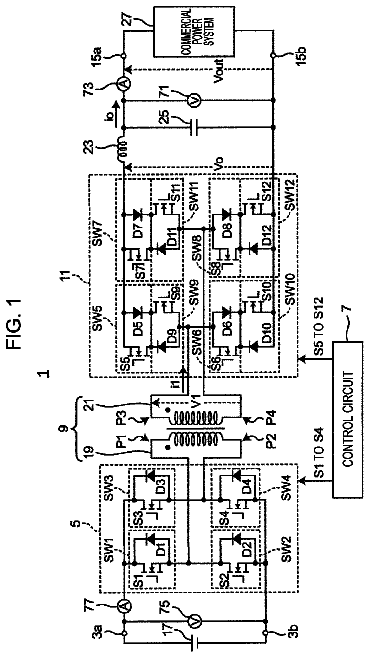
FIG. 1 is a block diagram illustrating the configuration of a power conversion device 1 according to the first exemplary embodiment. The power conversion device 1 includes terminals 3 a and 3 b , a primary side inverter circuit 5 , a transformer 9 , a secondary side converter circuit 11 , a filter circuit 13 , terminals 15 a and 15 b , voltmeters 71 and 75 , ammeters 73 and 77 , snubber circuits 101 to 103 , and a control circuit 7 . The power conversion device 1 is connected to a DC power source 17 via the terminals 3 a and 3 b and is connected to a commercial power system 27 via the terminals 15 a and 15 b . The power conversion device 1 is a power conditioner that bidirectionally converts power between the DC power source 17 and the commercial power system 27 and transmits the power.
The DC power source 17 is, for example, a storage battery, a solar cell, a fuel cell. A positive electrode of the DC power source 17 is electrically connected to the terminal 3 a of the power conversion device 1 , and a negative electrode of the DC power source 17 is electrically connected to the terminal 3 b of the power conversion device 1 . The power of the DC power source 17 is supplied to the primary side inverter circuit 5 via the terminals 3 a and 3 b . The transformer 9 is a high-frequency transformer including a primary winding 19 and a secondary winding 21 magnetically coupled to each other. Terminals P 1 and P 2 of the primary winding 19 are connected to the output terminals of the primary side inverter circuit 5 . Terminals P 3 and P 4 of the secondary winding 21 are connected to the input terminals of the secondary side converter circuit 11 . The transformer 9 insulates the primary side inverter circuit 5 from the secondary side converter circuit 11 . When the power conversion device 1 operates in a power supply mode, the transformer 9 supplies the power from the primary side inverter circuit 5 to the secondary side converter circuit 11 therethrough. In contrast, when the power conversion device 1 operates in a power regeneration mode, the transformer 9 regenerates the power from the secondary side converter circuit 11 to the primary side inverter circuit 5 therethrough. These modes are described in more detail below.
FIG. 2 is a circuit diagram illustrating the detailed configuration of the primary side inverter circuit 5 illustrated in FIG. 1 . In FIG. 2 , the circuits on the secondary side are not illustrated. The primary side inverter circuit 5 is connected between the terminals 3 a and 3 b and the primary winding 19 of the transformer 9 . The primary side inverter circuit 5 is a high-frequency inverter that converts a DC voltage supplied from the DC power source 17 into a high-frequency voltage (an AC voltage) of, for example, 20 kHz. The primary side inverter circuit 5 includes four switching elements SW 1 to SW 4 . The switching elements SW 1 to SW 4 are bridge-connected to form a full-bridge circuit. Each of the switching elements SW 1 to SW 4 includes one of switches S 1 to S 4 and one of diodes D 1 to D 4 . The switches S 1 to S 4 are field effect transistors, for example. Each of the diodes D 1 to D 4 is connected between the source and the drain of a corresponding one of the switches S 1 to S 4 . That is, each of the diodes D 1 to D 4 is connected in parallel with the corresponding one of the switches S 1 to S 4 . Each of the diodes D 1 to D 4 may be a body diode of the corresponding one of the switch S 1 to S 4 or may be externally connected to the corresponding one of the switches S 1 to S 4 .
The switches S 1 to S 4 may be, for example, npn insulated gate bipolar transistors instead of the field effect transistors. In this case, the diodes D 1 , D 2 , D 3 , and D 4 are provided as freewheeling diodes. The diode D 1 is connected between the emitter and the collector of the switch S 1 so that a current flows through the diode D 1 in a direction opposite to the direction in which a current flows in the switch S 1 when the switch S 1 is closed. That is, the anode of the diode D 1 is connected to the emitter of the switch S 1 , and the cathode of the diode D 1 is connected to the collector of the switch S 1 . The diodes D 2 to D 4 are connected to the switches S 2 to S 4 , respectively, in the same manner.
The control circuit 7 opens the switches S 2 and S 3 when the switches S 1 and S 4 are closed and closes the switches S 2 and S 3 when the switches S 1 and S 4 are open.
FIG. 3 is a circuit diagram illustrating the detailed configuration of the secondary side converter circuit 11 illustrated in FIG. 1 . In FIG. 3 , the circuits on the primary side are not illustrated. The secondary side converter circuit 11 is connected between the secondary winding 21 and the terminals 15 a and 15 b (refer to FIG. 1 ). The secondary side converter circuit 11 is a direct AC converter that directly converts the high-frequency voltage supplied from the transformer 9 into a commercial AC voltage of 50 Hz or 60 Hz. The secondary side converter circuit 11 includes eight switching elements SW 5 to SW 12 . Each of the switching elements SW 5 to SW 12 includes one of switches S 5 to S 12 and one of diodes D 5 to D 12 . The switches S 5 to S 12 are, for example, MOSFETs. Each of the diodes D 5 to D 12 is connected between the source and the drain of a corresponding one of the switches S 5 to S 12 . That is, each of the diodes D 5 to D 12 is connected in parallel with the corresponding one of the switches S 5 to S 12 . Each of the diodes D 5 to D 12 may be a body diode of the corresponding one of the switch S 5 to S 12 or may be externally connected to the corresponding one of the switches S 5 to S 12 . By combining the switches S 5 to S 12 each formed from a MOSFET with the diodes D 5 to D 12 , respectively, the switching elements SW 5 to SW 12 pass a current in one direction when being open and pass a current bidirectionally when being closed.
As used herein, the switching elements SW 5 to SW 12 may be referred to as “a first switching element SW 5 to an eighth switching element SW 12 ”, and the switches S 5 to S 12 may be referred to as “a first switch S 5 to an eighth switch S 12 . The switching elements SW 5 to SW 12 are examples of “first to eighth switch circuits” in the present disclosure, and the switches S 5 to S 12 are examples of “first to eighth switch” in the present disclosure.
The first switching element SW 5 and the fifth switching element SW 9 are connected in series between the terminal 15 a and the terminal P 3 so that the direction in which a current flows in the first switching element SW 5 and the direction in which a current flows in the fifth switching element SW 9 are opposite to each other when being open (that is, the forward directions of the diodes D 5 and D 9 are opposite to each other). The drains of the first switch S 5 and the fifth switch S 9 are connected to each other, or the sources thereof are connected to each other. Either the first switching element SW 5 or the fifth switching element SW 9 may be disposed close to the terminal P 3 .
The second switching element SW 6 and the sixth switching element SW 10 are connected in series between the terminal 15 b and the terminal P 3 so that the direction in which a current flows in the second switching element SW 6 and the direction in which a current flows in the sixth switching element SW 10 are opposite to each other when being open (that is, the forward directions of the diodes D 6 and D 10 are opposite to each other). The drains of the second switch S 6 and the sixth switch S 10 are connected to each other, or the sources thereof are connected to each other. Either the second switching element SW 6 or the sixth switching element SW 10 may be disposed close to the terminal P 3 .
The third switching element SW 7 and the seventh switching element SW 11 are connected in series between the terminal 15 a and the terminal P 4 so that the direction in which a current flows in the third switching element SW 7 and the direction in which a current flows in the seventh switching element SW 11 are opposite to each other when being open (that is, the forward directions of the diodes D 7 and D 11 are opposite to each other). The drains of the third switch S 7 and the seventh switch S 11 are connected to each other, or the sources thereof are connected to each other. Either the third switching element SW 7 or the seventh switching element SW 11 may be disposed close to the terminal P 4 .
The fourth switching element SW 8 and the eighth switching element SW 12 are connected in series between the terminal 15 b and the terminal P 4 so that the direction in which a current flows in the fourth switching element SW 8 and the direction in which a current flows in the eighth switching element SW 12 are opposite to each other when being open (that is, the forward directions of the diodes D 8 and D 12 are opposite to each other). The drains of the fourth switch S 8 and the eighth switch S 12 are connected to each other, or the sources thereof are connected to each other. Either the fourth switching element SW 8 or the eighth switching element SW 12 may be disposed close to the terminal P 4 .
The first switching element SW 5 and the second switching element SW 6 are disposed so that the currents flow in the same direction in a path that extends from the terminal 15 a to the terminal 15 b and that includes the first switching element SW 5 , the second switching element SW 6 , the fifth switching element SW 9 , and the sixth switching element SW 10 (that is, the forward directions of the diodes D 5 and D 6 are the same) when being open.
The third switching element SW 7 and the fourth switching element SW 8 are disposed so that the currents flow in the same direction in a path that extends from the terminal 15 a to the terminal 15 b and that includes the third switching element SW 7 , the fourth switching element SW 8 , the seventh switching element SW 11 , and the eighth switching element SW 12 (that is, the forward directions of the diodes D 7 and D 8 are the same) when being open.
The first switching element SW 5 and the third switching element SW 7 are disposed so that the currents flow in the opposite directions in a path that extends from the terminal P 3 to the terminal P 4 and that includes the first switching element SW 5 , the third switching element SW 7 , the fifth switching element SW 9 , and the seventh switching element SW 11 (that is, the forward directions of the diodes D 5 and D 7 are opposite to each other) when being open.
The control circuit 7 controls the amplitude of at least one of the output voltage and the output current at the terminals 15 a and 15 b by switching on/off the first switch S 5 to the eighth switch S 12 . The control is described in more detail below.
Referring back to FIG. 1 , the configuration of the power conversion device 1 is described below. The filter circuit 13 includes coils 23 and 24 and a capacitor 25 .
The coil 23 is disposed between one of the two output terminals of the secondary side converter circuit 11 and the terminal 15 a . The coil 24 is disposed between the other output terminal of the secondary side converter circuit 11 and the terminal 15 b . The capacitor 25 is connected between the two output terminals of the secondary side converter circuit 11 . The coils 23 and 24 and the capacitor 25 constitute a filter circuit that smoothes an AC signal output from the secondary side converter circuit 11 . In this manner, the pulse wave AC signal output from the secondary side converter circuit 11 is converted into a sine wave AC signal having an amplitude in accordance with the pulse width.
The voltmeter 75 measures the input voltage of the primary side inverter circuit 5 (the voltage between the terminals 3 a and 3 b ) and notifies the control circuit 7 of the value of the input voltage. The ammeter 77 measures the input current of the primary side inverter circuit 5 and notifies the control circuit 7 of the value of the input current.
The voltmeter 71 measures the output voltage (the voltage between the terminals 15 a and 15 b ) of the power conversion device 1 and notifies the control circuit 7 of the value of the output voltage. The ammeter 73 measures the output current of the power conversion device 1 and notifies the control circuit 7 of the value of the output current.
The control circuit 7 controls the primary side inverter circuit 5 and the secondary side converter circuit 11 .
When electric power is supplied from the DC power source 17 to the commercial power system 27 (electric power sale) or when the DC power source 17 is charged by the power supplied from the commercial power system 27 , the terminals 15 a and 15 b are connected to the commercial power system 27 .
Ringing of the voltage and current may occur due to switching of the primary side inverter circuit 5 and the secondary side converter circuit 11 . To prevent the occurrence of ringing, snubber circuits 101 to 103 are provided.
The snubber circuit 101 includes a capacitor C 10 connected between both ends of the primary winding 19 .
The snubber circuit 102 includes a capacitor C 20 and a resistor R 20 connected in series with each other between both ends of the secondary winding 21 .
The snubber circuit 103 is a clamping circuit including a diode bridge formed from diodes D 21 to D 24 , a capacitor C 21 , and a resistor R 21 . The diode bridge includes a node between the diodes D 21 and D 22 and a node between the diodes D 23 and D 24 as AC input terminals. The diode bridge further includes a node between the diodes D 21 and D 23 and a node between the diodes D 22 and D 24 as DC output terminals. The AC input terminals of the diode bridge are connected to both ends of the secondary winding 21 . The capacitor C 21 and the resistor R 21 are connected in parallel between the DC output terminals of the diode bridge.
The operation performed by the power conversion device 1 illustrated in FIG. 1 is described below.
FIG. 4 is a circuit diagram of a power conversion device 1 A of a comparative example for describing the operation performed by the power conversion device 1 illustrated in FIG. 1 . The power conversion device 1 A illustrated in FIG. 4 has a configuration obtained by removing the snubber circuits 101 to 103 from the power conversion device 1 illustrated in FIG. 1 . A voltage V 1 is generated between the terminals P 3 and P 4 of the secondary winding 21 . The primary side inverter circuit 5 generates an output current ID. The secondary side converter circuit 11 generates an output voltage Vo and generates an output current io. By smoothing the output voltage Vo of the secondary side converter circuit 11 by the filter circuit 13 , the output voltage Vout of the power conversion device 1 is generated at the terminals 15 a and 15 b.
FIG. 5 is a timing diagram illustrating the operation performed by the power conversion device 1 A illustrated in FIG. 4 . In FIG. 5 , the abscissa represents the time, and the ordinate represents the voltage applied to the control terminals of the switches S 1 to S 12 . In this description, it is assumed that the switches S 1 to S 12 are closed when a positive voltage is applied to the control terminal.
The DC power source 17 produces a DC voltage VE.
According to the operation illustrated in FIG. 5 , the control circuit 7 applies a drive signal having a duty ratio of about 50% to the switches S 1 to S 4 of the primary side inverter circuit 5 while taking into account the dead time. As a result, a pulse wave AC signal is generated. The pulse wave AC signal is +VE during period T 01 , is −VE during period T 02 , and changes from +VE to −VE or from −VE to +VE during the remaining period. The generated pulse wave AC signal is applied to the primary winding 19 of the transformer 9 . Subsequently, in the secondary winding 21 of the transformer 9 , a pulse wave AC signal is also generated. The pulse wave AC signal is +VE during the period T 01 , is −VE during the period T 02 , and changes from +VE to −VE or from −VE to +VE during the remaining period. The voltage on the primary side of the transformer 9 and the voltage on the secondary side depend on the ratio of the number of turns of the primary winding 19 to the number of turns of the secondary winding 21 . In this example, it is assumed that the turn ratio is 1:1.
PWM control is performed on the switching elements SW 5 to SW 12 (that is, the switches S 5 to S 12 ) of the secondary side converter circuit 11 in each of the period T 01 and the period T 02 . In this manner, an AC voltage of a desired frequency is output to the terminals 15 a and 15 b . The voltage between the terminals P 3 and P 4 of the secondary winding 21 varies from +VE to −VE. Accordingly, when the switching elements SW 5 to SW 12 are MOSFETs having a body diode, the switching elements SW 5 to SW 12 are connected so that a current does not flow through the body diode. More specifically, the switching elements SW 5 and SW 9 are connected in series between the terminal P 3 and the terminal 15 a so that the forward directions of the diodes are opposite to each other. The switching elements SW 6 and SW 10 are connected in series between the terminal P 3 and the terminal 15 b so that the forward directions of the diodes are opposite to each other. The switching elements SW 7 and SW 11 are connected in series between the terminal P 4 and the terminal 15 a so that the forward directions of the diodes are opposite to each other. The switching elements SW 8 and SW 12 are connected in series between the terminal P 4 and the terminal 15 b so that the forward directions of the diodes are opposite to each other. That is, the switching elements SW 5 and SW 9 are regarded as one switching element, the switching elements SW 6 and SW 10 are regarded as one switching element, the switching elements SW 7 and SW 11 are regarded as one switching element, and the switching elements SW 8 and SW 12 are regarded as one switching element. In such a case, the secondary side converter circuit 11 is equivalent to an existing inverter circuit.
The operation performed during the period T 1 in FIG. 5 is described below. At this time, the pulse wave AC signal output from the primary side inverter circuit 5 is positive. The switch S 5 may be opened, and the switch S 9 may be opened or closed, the switch S 7 is closed, the switch S 11 is closed, the switch S 6 may be opened or closed, the switch S 10 is open, the switch S 8 is closed, and the switch S 12 is closed. Thus, a current flows through a path illustrated in FIG. 6 or 9 . At this time, the output voltage Vo of the secondary side converter circuit 11 becomes 0 V, which is lower than the voltage Vout at the terminals 15 a and 15 b . Accordingly, the current gradually decreases.
The operation performed during the period T 2 illustrated in FIG. 5 is described below. At this time, the pulse wave AC signal output from the primary side inverter circuit 5 is positive. The switch S 5 is closed, the switch S 9 is closed, the switch S 7 may be either on or off, the switch S 11 is open, the switch S 6 may be either on or off, the switch S 10 is open, the switch S 8 is closed, and the switch S 12 is closed. Thus, a current flows through the path illustrated in FIG. 7 or 10 . At this time, the output voltage Vo of the secondary side converter circuit 11 is equal to the voltage +VE between the terminals P 3 and P 4 of the secondary winding 21 , which is higher than the voltage Vout at the terminals 15 a and 15 b . Accordingly, the current gradually increases.
The operation performed during the period T 9 illustrated in FIG. 5 is described below. The period T 9 is a period in which the polarity of the voltage between the terminals P 3 and P 4 of the secondary winding 21 is reversed. The switch S 5 is open, the switch S 9 is open, the switch S 7 is closed, the switch S 11 is closed, the switch S 6 is open, the switch S 10 is open, the switch S 8 is closed, and the switch S 12 is closed. Thus, a current flows through a path illustrated in FIG. 6 or 9 . If, at this time, all of the switches S 1 to S 4 are open, the voltage output from the primary side inverter circuit 5 is inverted from positive to negative. If the voltage between the terminals P 1 and P 2 of the primary winding 19 is inverted, the voltage between the terminals P 3 and P 4 of the secondary winding 21 is also inverted. At this time, since the current flows through the path illustrated in FIG. 6 or 9 , the primary side of the transformer 9 is not affected and, thus, the inverting operation can be stably performed.
The operation performed during the period T 3 illustrated in FIG. 5 is described below. At this time, the pulse wave AC signal output from the primary side inverter circuit 5 is negative. The switch S 9 is open, the switch S 5 may be either on or off, the switch S 7 is closed, the switch S 11 is closed, the switch S 10 may be either on or off, the switch S 6 is open, the switch S 8 is closed, and the switch S 12 is closed. Thus, a current flows through the path illustrated in FIG. 6 or 9 . At this time, the output voltage Vo of the secondary side converter circuit 11 becomes 0 V, which is lower than the voltage Vout at the terminals 15 a and 15 b . Accordingly, the current gradually decreases.
The operation performed during the period T 4 illustrated in FIG. 5 is described below. At this time, the pulse wave AC signal output from the primary side inverter circuit 5 is negative. The switch S 5 may be opened or closed, the switch S 9 is open, the switch S 7 is closed, the switch S 11 is closed, the switch S 6 is closed, the switch S 10 is closed, and the switch S 8 is turned either on or off, and the switch S 12 is open. Thus, a current flows through the path illustrated in FIG. 8 or 11 . At this time, the output voltage Vo of the secondary side converter circuit 11 is equal to the voltage −VE between the terminals P 3 and P 4 of the secondary winding 21 , which is higher than the voltage Vout at the terminals 15 a and 15 b . Accordingly, the current gradually increases.
As described above, during the period in which the voltage V 1 between the terminals P 3 and P 4 of the secondary winding 21 is +VE, the period in which the voltage V 1 is −VE, and the period in which the polarity of the voltage V 1 is reversed, the switches to be conducted are changed to apply a voltage.
Note that during the above-described periods T 1 to T 4 and T 9 , no current flows in the switch that is either on or off even if the switch is closed.
Let T be the length of period T 01 , let Ton be the length of period T 2 , and let Toff (=T−Ton) be the length of period T 1 . In addition, let L be the inductance of the coil 23 . Then, during the period T 2 , the voltage +VE is applied to the coil 23 . An increment Δioa of the current io of the coil 23 during the period T 2 is given as follows: Δ ioa =( VE−V out)/ L×T on
During the period T 2 , a voltage of 0 V is applied to the coil 23 . A decrement Δiob of the current io of the coil 23 during the period T 2 is given as follows: Δ iob =Vout/ L ×( T−T on)
As in the periods T 1 and T 2 , even in the periods T 3 and T 4 , the current io of the coil 23 increases or decreases.
During the period T 2 , ripple occurs in the current io of the coil 23 in accordance with the voltage applied to the coil 23 .
In the stable state, Δioa and Δiob are the same, so that the following equation holds: V out= T on/ T×VE=D×VE where D is the duty ratio of the switches S 1 to S 4 .
By changing the duty ratio D through PWM control, AC output is available.
Since, during the Ton period, the power is supplied from the power conversion device 1 to the commercial power system 27 , the Ton period is referred to as a “power supply period”. In addition, since, during the Toff period, the current circulates in a loop including the terminals 15 a and 15 b which are short-circuited without passing through the secondary winding 21 , the Toff period is referred to as a “circulation period”.
FIGS. 14A to 14H are diagrams for describing the synchronous rectification sequence performed by the secondary side converter circuit 11 when the voltage V 1 between the terminals P 3 and P 4 of the secondary winding 21 illustrated in FIG. 4 is inverted.
FIG. 14A illustrates a state in which a positive voltage V 1 is applied between the terminals P 3 and P 4 of the secondary winding 21 illustrated in FIG. 4 and a positive current flows through the commercial power system 27 . FIG. 14H illustrates a state in which a negative voltage V 1 is applied between the terminals P 3 and P 4 of the secondary winding 21 illustrated in FIG. 4 and a positive current flows through the commercial power system 27 . When the voltage V 1 between the terminals P 3 and P 4 of the secondary winding 21 illustrated in FIG. 4 is inverted and transition from the state illustrated in FIG. 14A to the state illustrated in FIG. 14H occurs, the states illustrated in FIGS. 14B to 14G sequentially appear. In the states illustrated in FIGS. 14B to 14G , only the circulating current that does not pass through the secondary winding 21 flows through the secondary side converter circuit 11 and, thus, the voltage between the terminals 15 a and 15 b in FIG. 4 becomes zero. In this way, by providing the circulation period before the voltage V 1 between the terminals P 3 and P 4 of the secondary winding 21 is inverted, only an excitation current flows in the primary side. In this manner, the loss caused by switching off the switches S 1 to S 4 of the primary side inverter circuit 5 can be reduced.
In addition, by controlling the switches S 7 , S 8 , S 11 and S 12 as illustrated in FIGS. 14B to 14G (synchronous rectification), the current flows through the switches S 11 and S 12 in FIGS. 14C to 14F instead of through the diodes D 11 and D 12 . As a result, the loss is reduced more than in the case where the current flows through the diodes D 11 and D 12 . Furthermore, by controlling the switches S 6 and S 10 as illustrated in FIGS. 14E to 14H (synchronous rectification), the current flows through the switch S 10 instead of through the diode D 10 in FIG. 14H , resulting in a decrease in the loss more than in the case in which the current flows through the diode D 10 . Similarly, when transition from the state illustrated in FIG. 14H to the state illustrated in FIG. 14A occurs, the current flows through the switch S 9 instead of through the diode D 9 in FIG. 14A by controlling the switches S 5 and S 9 (synchronous rectification) as illustrated in FIGS. 14D to 14A . As a result, the loss is reduced more than in the case in which the current flows through the diode D 9 .
The occurrence of ringing in the power conversion device 1 A illustrated in FIG. 4 is described below.
The description continues in the full USPTO document.
 Lapsed, fee not paid4 drawings