Lapsed, fee not paid10 drawings
Hardware & Electronics · US 9,865,109 B2
Systems and methods for controlling an electronic lock for a remote device
A system for controlling an electronic lock of a remote device is disclosed.
US 9,865,113 B2 · Assignee: Volkswagen Aktiengesellschaft · Inventors: Maiwand; Heiko et al.
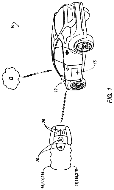
Sheet 1 of 18 from the published document. All sheets in the USPTO PDF
A system for providing dynamic access to a vehicle via a plurality of devices. A device and/or a server of an authentication network stored fob data relating to one or more key fobs linked to the vehicle, and device data that includes data relating to one or more devices that are authorized to access the vehicle. The vehicle receives an access request indicating that a new device is requesting access to the vehicle, whereupon a challenge may be transmitted to one or more of the authorized devices. The one or more devices may respond, granting access to vehicle functions. The vehicle and/or authentication network generate a secure fob key and access limitations based on the response and transmit the secure fob key to the new device. The new device may be authenticated to access vehicle functions subject to the limitation based at least in part on the fob key.
1 of 18 drawing sheets so far from the published document, cropped to the drawing. Every sheet is in the USPTO PDF.
What the patent claimed, word for word. All of it is now free to use.
The present disclosure is directed to vehicle security and access. More specifically, the present disclosure is directed to authenticating and/or authorizing users and dynamically identifying authorized users for one or more vehicles to allow access to vehicle functions such as door locks, ignition and the like. Further, the present disclosure is directed to managing BACKGROUND
A keyless entry system is an electronic lock that controls access to a building or vehicle without using a traditional mechanical key. The term keyless entry system originally meant a lock controlled by a keypad located at or near the driver's door, that required pressing a predetermined (or self-programmed) numeric code for entry. The term remote keyless system (RKS), also called keyless entry or remote central locking, refers to a lock that uses an electronic remote control as a key which is activated by a handheld device or automatically by proximity. Widely used in automobiles, an RKS performs the functions of a standard car key without physical contact. When within a few yards of the car, pressing a button on the remote can lock or unlock the doors, and may perform other functions. A remote keyless system can include both a remote keyless entry system (RKE), which unlocks the doors, and a remote keyless ignition system (RKI), which starts the engine.
Keyless remotes contain a short-range radio transmitter, and must be within a certain range, usually 5-20 meters, of the car to work. When a button is pushed, it sends a coded signal by radio waves to a receiver unit in the car, which locks or unlocks the door. Most RKEs operate at a frequency of 315 MHz for North America-made cars and at 433.92 MHz for European, Japanese and Asian cars. Modern systems implement encryption to prevent car thieves from intercepting and spoofing the signal. The functions of a remote keyless entry system are contained on a key fob or built into the ignition key handle itself. Buttons are dedicated to locking or unlocking the doors and opening the trunk or tailgate. On some vehicles, such as minivans, power sliding doors can be opened/closed remotely. Some cars will also close any open windows and roof when remotely locking the car. Some remote keyless fobs also feature a red panic button which activates the car alarm as a standard feature. Further adding to the convenience, some cars' engines with remote keyless ignition systems can be started by the push of a button on the key fob, and convertible tops can be raised and lowered from outside the vehicle while it's parked. On cars where the trunk release is electronically operated, it can be triggered to open by a button on the remote. Conventionally, the trunk springs open with the help of hydraulic struts or torsion springs, and thereafter may be lowered manually. In other configurations, trunks or tailgates may have a motorized assist that can both open and close the tailgate for easy access and remote operation.
A smart key is an electronic access and authorization system that allows the driver to keep the key fob pocketed when unlocking, locking and starting the vehicle. The key is identified via one of several antennas in a car's bodywork and a radio pulse generator in the key housing. Depending on the system, the vehicle is automatically unlocked when a button or sensor on the door handle or trunk release is pressed. Vehicles with a smart key system may be fitted with a mechanical backup, usually in the form of a spare key blade supplied with the vehicle.
Currently, vehicle access systems are relatively inflexible, in that they typically limit access only to users in physical possession of a key fob specific to one vehicle. Most configurations do not have effective means in which grant access to individuals based on dynamic permissions, while retaining the security and convenience of a key fob. Technologies and techniques are needed to provide dynamic user access, and manage that access, among a plurality of users via secure communications while providing a positive user experience for access through passive keyless entry (PKE) and other similar devices.
Various apparatus, systems and methods are disclosed herein relating to vehicle security and the dynamic granting of access to vehicle functions via a plurality of devices.
In some illustrative embodiments, a system is disclosed for authorizing access to vehicle functions for a vehicle, wherein the system comprises a processor; data storage, operatively coupled to the processor, the data storage configured to store fob data relating to a key fob linked to the vehicle, and device data comprising data relating to one or more devices that are authorized to access the vehicle; and communications circuitry, operatively coupled to the processor, the communications circuitry configured to receive an access request indicating that a new device is requesting access to the vehicle, wherein the processor is configured to transmit a challenge via the communications circuitry to one of the one or more devices that are authorized to access the vehicle and receive a response thereto, wherein the processor is configured to generate a secure fob key based on the response and transmit the secure fob key to the new device, wherein the secure fob key comprises limitation data for setting parameters on vehicle access, and wherein the processor is configured to authenticate the new device based at least in part on the secure fob key, wherein the new device is authorized to access the vehicle subject to the limitation data upon completion of the authentication.
In some illustrative embodiments, a method is disclosed for authorizing access to a vehicle, comprising the steps of storing fob data in a data storage operatively coupled to a processor, wherein the fob data relates to a key fob linked to the vehicle; storing device data in the data storage, the device data comprising data relating to one or more devices that are authorized to access the vehicle; receiving, via communications circuitry operatively coupled to the processor, an access request from the vehicle indicating that a new device is requesting access to the vehicle; transmitting a challenge via the communications circuitry to one of the one or more devices that are authorized to access the vehicle; receiving a response via the communications circuitry; generating, via the processor, a secure fob key based on the response and transmitting the secure fob key to the new device, wherein the secure fob key comprises limitation data for setting parameters for vehicle access; and authenticating the new device based at least in part on the fob key, wherein the new device is authorized to access the vehicle, subject to the limitation data, upon completion of the authentication.
In some illustrative embodiments, a vehicle is disclosed for authorizing access for vehicle functions for a new device, comprising a processor; data storage, operatively coupled to the processor, the data storage configured to store fob data relating to a key fob linked to the vehicle, and device data comprising data relating to one or more devices that are authorized to access the vehicle; and communications circuitry, operatively coupled to the processor, the communications circuitry comprising antennas for detecting the presence of a user and configured to receive an access request from the new device requesting access to the vehicle, wherein the processor is configured to message the one or more devices that are authorized to access the vehicle, via an authorization network, that the access request from the new device has been made, wherein the communications circuitry is configured to receive a secure fob key for the new device based on a response to the message, the secure fob key comprising limitation data for setting parameters for vehicle access, and wherein the processor is configured to authenticate the new device based at least in part on the secure fob key, wherein the new device is authorized to access a vehicle function subject to the limitation data upon completion of the authentication.
The present invention is illustrated by way of example and not limitation in the figures of the accompanying drawings, in which like references indicate similar elements and in which:
FIG. 1 illustrates a systematic overview of a vehicle system to provide access to a vehicle including a plurality of receivers to activate one or more vehicle functions;
FIG. 2 schematically illustrates an approach of a vehicle user to a vehicle from different directions carrying an electronic device and a vehicle key;
FIG. 3 is an exemplary system illustrating vehicles paired with one or more portable devices and/or key fobs, wherein the portable devices are configured to communicate with a vehicle, a local computer and network for receiving and sending data and/or instructions under an embodiment;
FIG. 4 is an exemplary block diagram illustrating hardware components in a vehicle's electronics system, where a processor communicates and controls operation of door entry and ignition of a vehicle, and includes communications to send and receive data and/or instructions to the vehicle under an embodiment;
FIG. 5 is an exemplary illustration of a wireless pairing/bonding configuration that further includes protocols for securely pairing/bonding devices and vehicles under an embodiment;
FIG. 6 shows an illustrative method for registering fob keys for a particular vehicle and/or user, along with user device data and identification for network storage to allow dynamically managing vehicle access under an illustrative embodiment;
FIG. 7 shows an operating environment for the server of FIG. 3 for securing dynamic access authentication for transmission to one or more devices under an illustrative embodiment;
FIG. 8 shows an operating environment for the processing device of FIG. 3 for authenticating vehicle access challenges under an illustrative embodiment;
FIG. 9 shows a process flow for registering and authenticating a user fob and device for authorizing access for at least one user under an illustrative embodiment;
FIG. 10 shows an example of an authorization table that indicates authorized users and fobs for a plurality of vehicles under an illustrative embodiment;
FIG. 11A shows an example of an authorization table for a plurality of users where device identification (ID) data, passwords and/or trusted fobs are registered for vehicle access under an illustrative embodiment;
FIG. 11B shows an example of an authorization table for a plurality of users where device identification (ID) data, passwords and/or trusted fobs, together with paired fobs and devices for specific users, are registered for vehicle access under an illustrative embodiment;
FIG. 12 shows a process for a vehicle to detect authorized fobs and devices and to transmit one or more challenges to authorized devices, and to activate a security function and/or transmit notifications to authorized devices if a proper response is not received under an illustrative embodiment;
FIGS. 13A-13C show various simplified examples of user devices, with and without an associated fob, approaching a vehicle and requesting access to a vehicle under illustrative embodiments;
FIG. 14 shows a process flow for dynamically providing access and authentication from one device to another, where a registered and authenticated device allows recognition and access of other devices, along with access permissions under an illustrative embodiment;
FIG. 15 shows a system that includes a processing device and a server communicating via a network, wherein the system is configured to generate and manage fob keys between a device and a server for vehicle access and functions under an illustrative embodiment;
FIG. 16 shows a system for generating and managing one or more key fobs for one or more vehicles under an illustrative embodiment;
FIG. 17A shows an example of an authorization table that indicates authorized users and fobs for a plurality of vehicles, along with vehicle usage limitations under an illustrative embodiment;
FIG. 17B shows an example of an authorization table that indicates authorized users and fobs for a plurality of vehicles, along with vehicle usage limitations and further including a key fob refresh configuration under an illustrative embodiment
FIG. 18 shows a process flow for generating a fob key and appending fob key limits on vehicle usage, where the fob key may be refreshed and updated until a fob key limitation is reached; and
FIG. 19 shows a process flow for a vehicle for receiving and authenticating a fob key, wherein the authenticated fob key limitations are applied, vehicle data is reported and refreshed fob keys may be processed and managed under an illustrative embodiment.
Various embodiments will be described herein below with reference to the accompanying drawings. In the following description, well-known functions or constructions are not described in detail since they may obscure the invention in unnecessary detail.
It will be understood that the structural and algorithmic embodiments as used herein does not limit the functionality to particular structures or algorithms, but may include any number of software and/or hardware components. In general, a computer program product in accordance with one embodiment comprises a tangible computer usable medium (e.g., hard drive, standard RAM, an optical disc, a USB drive, or the like) having computer-readable program code embodied therein, wherein the computer-readable program code is adapted to be executed by a processor (working in connection with an operating system) to implement one or more functions and methods as described below. In this regard, the program code may be implemented in any desired language, and may be implemented as machine code, assembly code, byte code, interpretable source code or the like (e.g., via Scala Programming Language (Scala), C, C++, C#, Java, Actionscript, Objective-C, Javascript, CSS, XML, etc.). Furthermore, the term “information” as used herein is to be understood as meaning digital information and/or digital data, and that the term “information” and “data” are to be interpreted as synonymous.
Turning to FIG. 1 , a vehicle 200 may comprise a vehicle system 100 for activating at least one vehicle component 116 . A vehicle component 116 can be any component at the vehicle that can be activated by at least another component inside or outside the vehicle 200 . Further details of this configuration may be found in U.S. patent application Ser. No. 14/065,996 to Akay, et al., titled “Vehicle System for Activating a Vehicle Component,” filed Oct. 29, 2013, the contents of which are incorporated by reference in their entirety herein. The vehicle component 116 may be activated electrically either directly or indirectly through other components, for example, by components operative to switch or regulate electronic current or voltage, such as, but not limited to, mechanical or solid-state relays, semiconductor switches (silicon controlled rectifiers, transistors, MOSFET, CMOS devices, Insulated Gate Bipolar Transistors (IGBT) etc.). As an example, by receiving a specific wireless signal by a vehicle receiver the vehicle fuel filler door may be unlocked or mechanically opened by driving a motorized mechanism to open the fuel filler door. After receiving the signal there might be various electronic circuits, e.g. for decrypting the received signal, verifying the signal, interpreting the signal, transferring and providing a signal for performing a vehicle function including, but not limited to, starting an engine, activating one or more lights, and/or driving an electric motor that is coupled to a door mechanism operable to open a door. This signal processing procedure may apply to any other vehicle component 116 as well.
FIG. 1 provides a systematic overview of a vehicle system 100 including a first and second receiver 112 , 114 to activate a vehicle component 116 or function. In one example, a vehicle user is approaching a vehicle 200 with at least one electronic device 102 and a matching vehicle access key 104 . The electronic device 102 is able to send out a wireless signal 106 to communicate with the first receiver 112 if the electronic device 102 is in a reception range ( 204 ) of the first receiver or other suitable signal. In certain illustrative embodiments, this signal can be a Bluetooth low energy signal or other suitable signal. Bluetooth low energy is specifically designed to draw very low amounts of power and therefore these sending and receiving devices are very energy efficient. Especially when used in a vehicle (e.g., 200 ), these devices can receive wireless signals 106 for a long time without the need to be shut down due to their quiescent current demand when the vehicle 200 is parked. In certain illustrative embodiments, when the user approaches the vehicle 200 , the first receiver 112 obtains a wireless signal 106 from the electronic device 102 , when the device 102 is in the reception range ( 204 ) of the first receiver 112 .
The wireless signal 106 of the electronic device 102 may comprise first identification data. This identification data may comprise a Unique Device Identifier (UDID), an Android ID, an international mobile equipment identity (IMEI), an international mobile subscriber identity (IMSI), and/or a user-created ID that resides on device (e.g., 102 ) memory and/or firmware. In one embodiment, the identification data comprises an identification code so that the vehicle system 100 can verify that a specific vehicle user carrying the electronic device 102 is in the reception range 204 . The vehicle system 100 comprises a memory 110 or memory device in which second identification data is stored. The memory 110 is able to store more than one set of second identification data, including a reference identification data for authentication. This is beneficial in the case when more than one user uses the vehicle 200 . By storing multiple sets of identification data the vehicle 200 is able to distinguish between the users and their preferences if the users each use a different set of first identification data. The identification data can also be dynamically generated and dynamically checked according to a predefined method to provide a higher level of safety when accessing the vehicle 200 . The identification data can also be encrypted by the electronic device 102 and decrypted by the vehicle system 100 .
If the first identification data match the at least second (reference) identification data stored in the memory 110 , the first receiver 112 may send a control signal to the second receiver 114 to access a matching vehicle access key 104 by a wireless signal 108 . If the second receiver 114 correctly identifies the vehicle key as a matching vehicle access key 104 , at least one vehicle component 116 is activated or operated. Vehicle components 116 include but are not limited to an ignition system, immobilizer, a central locking system, a vehicle door, a vehicle trunk lid, an automatic tailgate, a fuel filler door, an electrical charging port door release, an electrical charging plug release, a window opener, a sunroof, a convertible roof system, a vehicle infotainment system, a navigation system, a radio system, a climate control, a seat or mirror adjustment, a steering wheel adjustment, a pedal adjustment, an exterior or interior vehicle light, a driver assistance system or a vehicle camera. In certain illustrative embodiments, a vehicle user can also activate at least one vehicle component 116 by directly sending the wireless signal 108 from the matching vehicle access key 104 . In certain keyless vehicle entry systems, for example, as described in EP 1726753 B1, that, upon touching a vehicle door handle, capacitive sensors may detect such contact, and a keyless entry system may be activated and a receiver may detect the presence of a matching vehicle access key 104 .
In the example of FIG. 1 , the user interaction in vehicle system 100 may be advantageously more simplified. Not only can the central door locking system be activated at an earlier stage without the need of the user to touch a sensor but also the whole vehicle 200 or selected vehicle components 116 can be activated earlier. If the user does not have to touch a vehicle sensor to open the vehicle this is especially helpful if he is carrying something and returns to the vehicle. In this situation, the vehicle can additionally open the automatic tailgate.
FIG. 2 schematically illustrates an approach of a vehicle user to a vehicle 200 from a plurality of directions carrying an electronic device 102 as well as a vehicle access key 104 according to an illustrative embodiment. In a first example, the vehicle user is approaching the vehicle 200 from the rear. A dashed circle 204 schematically represents the reception range 204 of the first receiver 112 . At position 202 the vehicle user enters the reception range 204 of the first receiver 112 . The first identification data of the electronic device 102 can now be received by the first receiver 112 . If positively verified, the first receiver 112 wakes up the second receiver 114 and checks for a matching vehicle access key 104 . If the matching vehicle access key 104 is detected, all vehicle doors are unlocked.
In another embodiment, the electronic device 102 stores the parking position and heading of the vehicle 200 . In this example the electronic device 102 is a smartphone with a global positioning system (GPS), along with motion or acceleration sensors. When the user now approaches the vehicle 200 , the electronic device 102 or a computer executable program on a server can determine the current position of the smart phone and the direction the user is approaching the vehicle position. If the user approaches the vehicle from the rear and enters the reception range 204 at point 202 , the smart phone and the first receiver 112 start communicating with each other. The smart phone is identified as a device that has been successfully paired to exchange first identification data with the vehicle 200 . Since the user is approaching the vehicle 200 from the rear, a vehicle control command to activate a rear view camera 206 is sent to the vehicle 200 . The user stops in front of the trunk lid and an image recognition within the vehicle 200 is able to identify a person in an image or a video stream taken by the rear view camera 620 . The vehicle system 100 notices that the user is waiting, for example more than a predefined time, e.g. more than 2 seconds, in the rear of the vehicle 200 and subsequently opens the trunk lid and activates an automatic trunk lid opener.
In another example, the user enters the reception range 204 at a location 208 on the driver's side of the vehicle 200 . The electronic device 102 or a remote server program analyses the GPS or motion data of the electronic device 102 and compares that to the direction and position of the vehicle 200 . It is determined, that the user is approaching the vehicle 200 from the driver's side and subsequently unlocks the door on the driver's side.
FIG. 3 discloses an exemplary embodiment of a vehicle authentication system 300 , in which vehicles ( 302 , 304 ) and their respective key fobs ( 306 , 308 ) are paired or linked with respective portable devices ( 310 , 312 ), which may be configured to communicate with a local computer 316 as well as directly via wireless communication to authentication network 314 , which may comprise one or more servers 318 . As will be discussed in further detail below, “key fobs” may be distinguished from “fob keys” in that key fobs are specifically-designed hardware devices that are configured to operate exclusively or primarily with dedicated vehicle communications. In contrast, fob keys are dedicated software components or modules that may be implemented on key fobs, and also on general-purpose processing devices (e.g., smart phone) as well. Servers 318 may comprise wired and/or wireless communication interfaces to receive vehicle data, portable device data and other data from portable devices 310 , 312 as well as vehicles 302 , 304 . Additional data or instructions from computer 316 may be received via wired or wireless interface through network 314 . While not explicitly shown in FIG. 3 , servers 318 further comprise processors, storage and other peripheral devices known in the art to enable data processing and communication. For the purposes of the present disclosure, portable devices 310 , 312 may include any portable computing device capable of providing data communication over a wireless medium, including, but not limited to, a cellular phone, smart phone, tablet, laptop or PDA.
In the example of FIG. 3 , vehicle 302 is linked to key fob 306 , which may be configured to open or start vehicle 302 . Key fob 302 may additionally be equipped with buttons (which may be luminous), other lights, and/or a keypad. Vehicle 302 may also be configured to be independently linked or paired with portable device 310 (i.e., without requiring an initial direct linking with a key fob), belonging to a first user. After being paired with vehicle 302 (discussed in greater detail below in FIG. 9 ), portable device 310 will be able to receive and transmit data and/or instructions to vehicle 302 . The pairing of device 310 with vehicle 302 may be accomplished using any of a number of wireless communication protocols, including IEEE 802.15.4, Bluetooth, Wi-Fi, and NFC. In one exemplary embodiment, portable device 310 may also be linked with key fob 306 to provide a path for wireless data communication as well.
Vehicle 304 is linked to key fob 308 and device 312 belonging to a second user, similarly as described above. In this example, vehicles 302 and 304 may each be considered part of authenticated group 330 , 340 linked to users of portable devices 310 , 312 , which may be family members, co-workers, drive-share groups and the like. Once registered as such (discussed in greater detail in FIG. 9 below), devices 310 , 312 may exchange data and/or instructions with each other (indicated by connecting arrow in FIG. 3 ), as well as vehicles 302 , 304 of the authenticated group. Thus, in one example, portable device 310 would be configured to communicate with vehicles 302 and 304 as well as portable device 312 , while portable device 312 would similarly be configured to communicate with vehicle 304 and 302 , as well as portable device 310 . This embodiment may be advantageously used to allow multiple members to communicate with and/or control multiple vehicles within their authentication group, and further allowing data to be communicated to or from portable devices in a group 101 independently, in parallel, or in a “daisy-chain” fashion. Furthermore, as will be described in greater detail below, one authenticated device 310 , may be used to provide authentication to one or more other devices (e.g., 312 ). In certain illustrative embodiments, computer 316 may be used to authenticate and/or manage authentication of registered devices (e.g., 310 , 312 ).
Portable devices 310 , 312 may also be communicatively coupled to local computer 316 , which may be located at a user's home, place of work, etc. Local computer 316 may be a personal computer, laptop, or any other computing device capable of performing processing operations as well as sending and receiving data communication. In one embodiment, portable devices 310 , 312 communicates with local computer 316 wirelessly. In another embodiment portable devices 310 , 312 communicate with local computer 316 via a wired connection, which may include a dock or docking station (not shown). Local computer 316 may be suitably equipped with software allowing computer 316 to communicate with authentication network 314 , which may include one or more servers 318 . In one embodiment, local computer 316 communicates to authentication network 314 via HTTP over TCP/IP using a web browser interface using Java, JavaScript, DHTML, HTML5, Flash, Silverlight or any other suitable language or platform.
Portable devices 310 , 312 may also be configured to directly communicate with authentication network 314 via wireless and/or cellular connection as shown in FIG. 3 utilizing an on-device software application (or “app”), or through a web-based or mobile browser. In another exemplary embodiment, vehicles 302 , 304 may be equipped with wireless communication to enable vehicles 302 , 304 to also communicate wirelessly with authentication network 314 , similar to portable devices 310 , 312 .
In certain illustrative embodiments, vehicle authentication system 300 is configured to provide two-step or multi-step authentication for allowing entry and/or operation of vehicles 302 and/or 304 . Two-step authentication (also known as two-step verification) is a process involving two or more stages to verify the identity of an entity trying to access a vehicle. Generally speaking, the process involves multi-factor authentication which involves the presentation of two or more of three authentication factors: a possession factor, a knowledge factor and an inheritance factor. When accessing a vehicle, system 300 may execute a form of two-step verification. To determine who the individual is when accessing vehicle 302 , system may require the detection of a key fob 306 to show the individual has possession of a required item. In one embodiment, the system may alternately, or in addition, require the presence (“possession”) of portable device 310 that is registered in the system. To further verify that the individual is authorized to access vehicle 302 , the individual may be required to enter a personal identification number (PIN) (“knowledge factor”) on a door lock keypad on the surface of the vehicle door. In one embodiment, the individual may be required to enter a PIN on the portable device 310 , which is then communicated to vehicle 302 and/or authentication network 314 . In another embodiment, the individual may be required to physically press a button or series of buttons on key fob 306 for entering a PIN or authentication input. In a further embodiment, the vehicle may automatically receive secured device identification data (e.g., IMEI, IMSI) for authentication purposes. In one embodiment, inheritance factors may be utilized via the portable device 310 utilizing fingerprint or voice recognition embodied on the device itself.
Turning to FIG. 4 , an exemplary embodiment is provided illustrating components within a vehicle ( 302 - 304 ) for authentication, which may be incorporated into the embodiment of FIG. 1 , or may be configured as a stand-alone system. Processor 402 is responsible for operating and controlling doors 202 and associated locking mechanisms, as well as engine 408 operations and control. In one embodiment, processor 402 may be a stand-alone processor that communicates and controls a body controller in the vehicle to lock and unlock the doors 406 , and further communicates with an immobilizer or engine control unit (ECU) for controlling operation of the vehicle. In another embodiment, processor 402 may be two or more processors performing the same functions. In this example, the processors may be distributed among different units in the vehicle. The immobilizer may be embodied as static codes or rolling codes in a key fob or portable device that are recognized by an RFID loop around the lock barrel and checked against the vehicle's ECU for a match. If the code is not recognized, the ECU will not allow fuel to flow and ignition to take place. A circuit inside the key fob or portable device is activated by a small electromagnetic field which induces current to flow, which in turn broadcasts a unique binary code which is read by the vehicle's ECU. When the ECU determines that the coded key is both current and valid, the ECU activates the fuel-injection sequence.
Processor 402 is communicatively coupled to communications 412 , which may comprise one or more communication interfaces and associated circuitry for sending and receiving data and/or instructions from one or more portable devices and/or an authentication network. Communications 412 may include wired interfaces, such as USB or Firewire, as well as wireless interfaces, such as Bluetooth, Wi-Fi or cellular communication. Antennas 414 may comprise one or more antennas for detecting the presence of key fobs (e.g., 304 , 308 ) and/or portable devices (e.g., 310 , 312 ), and may be equipped with sensor technology (e.g., proximity sensors) for detecting a physical presence of a user. Antennas 414 may be integrated with communications 412 , or may be configured as a stand-alone system. Processor 402 is also coupled to storage 404 that may be configured to store software for executing authentication described herein, and also store data generated and/or received for authentication processing. Display/keypad 410 may be further provided to display information from processor 402 and to provide data entry capabilities for a user. The keypad may comprise a physical keypad, or may alternately be configured as a virtual keypad within the display as is known in the art.
Turning now to FIG. 5 , the figure illustrates an exemplary configuration 500 for communication among portable device(s) 310 , 312 and vehicle 302 , 304 utilizing a Bluetooth protocol. The configuration is particularly useful for pairing and bonding portable devices to vehicles (e.g., 302 , 304 ) and to each other. Generally speaking, two entities (e.g., device-device; device-vehicle) may become paired when they start with the same PIN and generate the same link key, and then use this key for authenticating at least a present communication session. The session can exist for the life of a L2CAP link or the life of an ACL link. Pairing can occur through an automatic authentication process if both devices already have the same stored PIN from which they can derive the same link keys for authentication. Alternatively, either or both applications can ask their respective users for manual PIN entry. Once entities are paired they can either store their link keys for use in subsequent authentications or discard them and repeat the pairing process each time they connect. If the link keys are stored, then the devices are bonded, enabling future authentications to occur using the same link keys and without requiring the user to input the PIN again. Bonding can expire immediately after the link is disconnected, after a certain time period expires, or never (permanently bonded). When bonding expires, the entities must repeat the pairing process again. Users may generate, receive and/or send data, including identification data and/or authentication data via user interface module 502 coupled one or more applications 504 , 506 that may communicate via transport protocols RFCOMM 510 coupled to L2CAP 512 . Each of the user interface 502 applications 504 , 506 , RFCOMM 510 and L2CAP 512 may communicate with security manager 508 .
In FIG. 5 , an exemplary security management configuration is illustrated, that may be incorporated into a host software package on device(s) 310 , 312 and vehicle(s) 302 , 304 . For greater flexibility, authentication and authorization can occur after determining the security level of the requested authentication service; in this case, authentication occurs after the ACL link is established. Of course, other authentication can occur with initial establishment of the ACL link. In FIG. 5 , security manager 508 resides on the Bluetooth host and communicates with L2CAP 512 and with link manager/controller 516 through host control interface (HCI) 514 . Typically, a connect request from a portable device to a vehicle (and vice-versa) arrives at L2CAP 512 , where the L2CAP 512 requests evaluation from security manager 508 . Security manager 508 looks up the requested service in database 522 for security information, and looks the requesting device's BD_ADDR or International Mobile Equipment Identity (IMEI) number in database 520 for access authorizations. Security manager 508 then begins the necessary authentication and (if needed) encryption procedures with the link manager 516 through HCI 514 . If authentication is determined to be positive, link manager 512 provides a response through HCI 514 , and L2CAP 512 finishes the connection setup process. The security manager architecture in FIG. 5 could be used to implement link-level (Mode 3 ) security as well.
The configuration of FIG. 5 may implement basic security operations primarily at the link manager/controller 516 levels. Link controller 516 can implement key-generating algorithms, random number processes, and basic communication of the various security parameters between a vehicle (e.g., 302 , 304 ) and a portable device (e.g., 310 , 312 ). Link manager 516 provides a set of commands that enable the formation of link management protocol packets containing the security parameters. HCI 514 provides a means for the host to communicate security items to the Bluetooth module for use by the link manager controller 516 . At the link layer, there may be several different entities used to maintain security. A PIN can be used as either a fixed number, preprogrammed into the Bluetooth unit, or a number that's entered by the user at the beginning of each secure session. There are several ways that a portable device (e.g., 310 , 312 ) and a vehicle (e.g., 302 , 304 ) (and/or another portable device in an authentication group) can be provided the same PIN: if the portable device and vehicle are being set up to exchange files and/or data, then each can ask for a password, in which a common PIN is derived from the link keys. In another embodiment, a vehicle (e.g., 302 , 304 ) may be set up with user authentication profiles comprising a database of BD_ADDR/IMEI values and associated PIN codes. The security manager 508 can enter these via an encrypted Bluetooth link or through an ordinary cable connection. When a device attempts to connect, the application asks for a PIN (or retrieves one that was previously stored), from which the link keys are derived. If the user's PIN matches, then both devices create the same link key and authentication and, if needed, encryption can proceed successfully. Under one embodiment, the PIN may be associated with a user rather than with the device.
The description continues in the full USPTO document.
About 6,268 words. The USPTO PDF has it with every drawing.
Fees are due 3.5, 7.5 and 11.5 years after grant. This patent expired on January 9, 2026, so the fee marked "not paid" was the one that went unpaid.
APPARATUS, SYSTEM AND METHOD FOR DYNAMIC IDENTIFICATION AND KEY MANAGEMENT FOR VEHICLE ACCESS
Filed Sep 2016 · published Dec 2017Apparatus, system and method for dynamic identification and key management for vehicle access
Filed Sep 2016 · granted Jan 2018Earlier publications, parents and continuations. None of them can still be enforced, or this patent would not be listed.
Prior art cited by the examiner or applicant. Useful when you check your own idea for novelty.
Everything on this page comes from the documents linked above.