 Lapsed, fee not paid6 drawings
Hardware & Electronics · US 9,864,548 B2
Memory module, electronic device and method
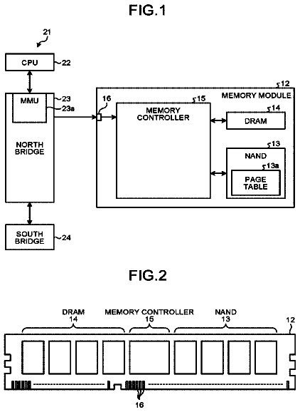
According to one embodiment, a memory module includes a volatile memory, a nonvolatile memory, and a controller.
US 9,864,909 B2 · Assignee: Huntington Ingalls Incorporated · Inventors: Bare; Brian et al.
Sheet 1 of 7 from the published document. All sheets in the USPTO PDF
A method for providing target object surface information to a mobile device user is presented. The method includes receiving a request for target object surface information from a mobile device, determining the pose of the mobile interface device relative to the target object, and obtaining target object surface information for one or more measurable target object surface parameters. The target object data is used to assemble augmented reality surface information configured for viewing in conjunction with a real-time view of the target object captured by the mobile interface device. The target object augmented reality surface information is then transmitted to the mobile device for display to the user.
This application relates generally to the use of augmented reality to display changes in dynamic environments and, more particularly, to the use of augmented reality to provide information and direction to users performing operations on or applying coatings to surfaces in such dynamic environments. Augmented reality (AR) provides a view of a physical, real-world environment whose elements are augmented (or supplemented) by computer-generated sensory input such as sound, text, graphics, or video. In a typical AR application, a data processor reviews a camera-captured image for cues that trigger the display of additional information and images along with a display of the captured image. While AR is useful for conveying information via a static display, it is particularly useful in dynamic situations and environments where images are captured and displayed in real-time and the information t
1 of 7 drawing sheets so far from the published document, cropped to the drawing. Every sheet is in the USPTO PDF.
What the patent claimed, word for word. All of it is now free to use.
This application relates generally to the use of augmented reality to display changes in dynamic environments and, more particularly, to the use of augmented reality to provide information and direction to users performing operations on or applying coatings to surfaces in such dynamic environments.
Augmented reality (AR) provides a view of a physical, real-world environment whose elements are augmented (or supplemented) by computer-generated sensory input such as sound, text, graphics, or video. In a typical AR application, a data processor reviews a camera-captured image for cues that trigger the display of additional information and images along with a display of the captured image.
While AR is useful for conveying information via a static display, it is particularly useful in dynamic situations and environments where images are captured and displayed in real-time and the information to be displayed using AR (hereinafter, “AR information”) changes. The ability to provide constant update to the AR information in response to changes in the environment and location and relative positioning of the user's display provides great utility in various applications including construction, repair, maintenance, and safety.
A particularly significant example of a dynamic spatial environment is the space on board a large ship. Not only does the ship itself move, its structure is flexible so that the position of a particular compartment, deck portion, supporting structure, or exterior surface in one part of the ship may change relative to other parts of the ship. Similar dynamic behavior can occur in tall buildings, construction sites, outdoor processing plants, roadways, bridges, etc.
In addition to changes in environmental structure, dynamic environments experience changes in an essentially infinite number of conditions. These can be as simple as changes in measurable atmospheric conditions (e.g., temperature and pressure) or as complex as changes in surface topography due to thermal expansion and contraction.
There are many instances where construction or maintenance operations on large structures such as ships require information on changes in the dynamic environment and/or differences between an intended design condition/configuration and the current as-built (or as-worn) condition/configuration. Many of these instances relate to application, modification, or removal of paint, insulation, or other surface covering/coating. Efficient completion of these tasks requires accurate and up-to-date information on the current and desired condition of the structural surface and any coating or other covering material defining some or all of that surface.
For as many different possible conditions there are in a given environment, there are as many instances where rapid communication of changes in such conditions to individuals operating in or on that environment is essential.
An illustrative aspect of the invention provides a method for providing information to a mobile interface device user for use in conducting an operation on a surface of a target object in a dynamic structural environment. The method comprises receiving on a central data processor from the mobile interface device over a communication network a request for target object surface information, determining a pose of the mobile interface device relative to the target object surface, and obtaining target object surface information for one or more measurable target object characteristics. The method further comprises assembling AR target object surface information for transmission to and display on the mobile interface device. The AR target object surface information is assembled using the target object surface information and is configured for viewing in conjunction with a real-time view of the target object captured by the mobile interface device. The method also comprises transmitting the AR target object information to the mobile interface device.
Another illustrative aspect of the invention provides an automated system for providing information to a mobile interface device for use in conducting an operation on a surface of a target object in a dynamic structural environment. The system comprises at least one mobile interface device configured for variable disposition within the dynamic structural environment, capturing information about the target object within the structural environment, and transmitting the target object information over a network. The system also comprises a local positioning system in communication with the at least one mobile interface device via the network and configured to provide information usable to determine a mobile interface device pose relative to the target object. The system further comprises a central processor comprising at least one data processing machine in communication with the at least one mobile interface device and the local positioning system via the network. The central processor is configured for receiving from a requesting one of the at least one mobile interface device a request for target object surface information, the request including information usable to determine the mobile interface device pose relative to the target object, determining the pose of the requesting mobile interface device relative to the target object, and obtaining target object surface information for one or more measurable target object characteristics. The central processor is further configured for assembling augmented reality (AR) target object surface information for transmission to and display on the mobile interface device. The AR target object surface information is assembled using the target object surface information and is configured for viewing in conjunction with a real-time view of the target object captured by the mobile interface device. The central processor is still further configured for transmitting the AR target object information to the mobile interface device.
The invention can be more fully understood by reading the following detailed description together with the accompanying drawings, in which like reference indicators are used to designate like elements, and in which:
FIG. 1 is a schematic representation of a system for providing AR information to a mobile interface device according to an embodiment of the invention;
FIG. 2 is a flow diagram of a method of providing target object information to a mobile interface device in a dynamic structural environment according to an embodiment of the invention;
FIG. 3 is a schematic representation of a system for providing target object surface information to a mobile interface device according to an embodiment of the invention;
FIG. 4 is an illustration of a mobile interface device user having a target object and exemplary AR surface deviation information displayed thereon in accordance with an embodiment of the invention;
FIG. 5 is an illustration of a three dimensional target object having discrete surface regions for coating application;
FIG. 6 is an illustration of a mobile interface device user having a camera-captured view of a target object and overlaid AR surface information displayed thereon in accordance with an embodiment of the invention; and
FIG. 7 is a flow diagram of a method of providing target object surface information to a mobile interface device according to an embodiment of the invention.
The present invention provides methods and systems for real-time display of AR information on a mobile device immersed in and movable within a dynamic environment. The challenges presented by this scenario include determination of the location of and orientation of the mobile device within the environment, recognition of variations in the spatial geometry of the environment, and detection/identification of changes in other measurable parameters associated with the environment or objects within the environment.
While the invention will be described in connection with particular embodiments, it will be understood that the invention is not limited to these embodiments. On the contrary, it is contemplated that various alternatives, modifications and equivalents are included within the spirit and scope of the invention as described.
While the dynamic structural environments used in many of the examples and illustrative embodiments used herein to describe the invention relate to ships and other vessels, it will be understood that the invention is not limited to such environments. The invention can be used in, without limitation, land vehicles, buildings and any other static or dynamically variable structure.
The systems of the invention use AR as the primary medium for presenting environment-related information to a user. AR allows presentation of such information on the mobile interface device in graphical or textual form overlaid or adjacent an environmental area or object as it appears in the camera-generated view on the device screen.
A generalized system 100 for generating and displaying real-time AR information according to an embodiment of the invention is illustrated in FIG. 1 . The system 100 is configured for obtaining and storing information on a dynamic structural environment such as a ship or building and objects disposed within that environment. The system 100 comprises a central processor 110 in communication with one or more mobile interface devices 101 via a communication network 102 . The central processor may include or be in communication with a relational database structure (not shown) as is described in U.S. patent application Ser. No. 14/210,650 (the “'650 Application), filed on Mar. 14, 2014, the complete disclosure of which is incorporated herein by reference in its entirety. In general, the central processor 110 is configured to receive captured object information from the mobile interface devices 101 and to extract information relating to the environment or an object in the environment, generate AR information for display on a requesting mobile interface device, and transmit the AR information to the requesting mobile interface device 101 .
The central processor 110 may include or be configured to receive information from a local positioning system 109 via the communications network 102 or a different network. The central processor may be configured to use the information from the local positioning system 109 in conjunction with information from a requesting mobile interface device 101 and known/stored structural information (e.g., a three dimensional model) to determine the pose of the mobile interface device 101 within the environment. As used herein, “pose” means the position (x,y,z) and orientation (θ,φ,ζ) of an object in a particular physical space. The system is configured to resolve spatial differences between the coordinate system established based on the known structural information and the data received from the local positioning system 109 that result from changes in the dynamic structure.
The central processor 110 is also configured to receive information from an environment data system 103 via the network 102 or another network. The environment data system 103 is configured for measurement or determination of parameters associated with the structural environment or an object or objects within the structural environment. As will be discussed in more detail, such parameters may include, but are not limited to spatially mapped or mappable data obtained from sensors (e.g., radiation or temperature sensors) with known locations in the structural environment, spatially mapped or mappable data (e.g., weight distribution or surface topography) associated with a particular object in the environment, and system or device status information (e.g., electrical circuit energization status). In some embodiments, the environmental data systems 103 may include a metrology system adapted to provide measurements of specific parameters for particular object types. The central processor 110 is configured to process information from the environmental data systems 103 and use it with the pose information for the requesting mobile interface device 101 to generate AR information that can be transmitted to the mobile interface device 101 for display.
In various embodiments of the invention, information processed by the central processor 110 may include asset location information from a global or local positioning system, visual or graphical information received from the mobile interface devices, observational information from users, and operational or other data from instrumentation systems associated with the environment or particular assets. Any or all of such information can be used by the central processor 110 to update object-related information and/or generate information for display via AR images that can be superimposed on the mobile device user's view of the environment or an object in the environment. The mobile interface devices used in the systems of the invention can make use of AR in a variety of ways that allow the user to conduct inspection, maintenance, repair, and replacement tasks in relation to particular assets. AR can also be used to assist a user in identifying safety hazards, locating objects, or simply navigating within the dynamic environment.
In some embodiments, the central processor 110 may be configured for processing information it receives for a particular object or structure in the environment and comparing that information to desired specifications or previously obtained information for that object or structure. Such information can be used to determine if a maintenance or other corrective operation should be performed. The central processor 110 may also be configured to generate AR representations of a deviation from the desired condition that can be displayed to mobile device user charged with correcting the deviation. As will be discussed in more detail hereafter, this could include any of various maintenance operations or corrective machining operations. In some embodiments, the environment data systems 103 may be configured to provide periodic or continuous updates to the central processor 110 regarding the status or condition of the object or structure undergoing such operations. This allows the central processor 110 to provide condition updates to the mobile device operator in real-time.
The mobile interface device 101 may be any mobile computing solution that is used by a user to facilitate communication with and display information from the central processor 110 . The mobile interface device 101 may be, for example, a tablet computer, a smartphone, or a wearable heads-up display. The mobile interface device 101 may have features including, but not limited to a processor, a display (such as a screen), a vision sensor (such as a camera), a microphone, one or more speakers, and wireless communications capabilities. The mobile interface device 101 may be, in a particular embodiment, a wearable head-mounted device (HMD) such as that described in U.S. application Ser. No. 14/210,730, filed Mar. 14, 2014, the complete disclosure of which is incorporated herein by reference in its entirety. In preferred embodiments, the mobile interface device 101 is equipped or configured to display AR images/information to a user. The mobile interface device 101 may include one or more accelerometers or other motion detection sensors. Each mobile interface device 101 may include one or more unique identifiers. In some embodiments, some or all of the mobile interface devices 101 may include one or more local positioning receivers, image and object recognition, audio queues, or electromagnetic field (EMF) receivers or detectors (for GPS, WiFi, or RFID reception or light detection).
In some embodiments, the mobile interface device 101 may be configured to receive information from the local positioning system 109 and to determine its own pose relative to the environment. This capability may be provided to the mobile device 101 in addition to or instead of configuring the central processor 110 to establish the pose of the mobile device 101 .
The communication network 102 may be a wireless network, a wired network or any combination of wireless network and wired network. In a preferred embodiment, the communications network 102 is a wireless communications network, allowing the mobile interface devices 101 to communicate wirelessly with the central processor 110 . The communication network 102 may, in particular, be or include a wireless LAN, a Global System for Mobile Communication (“GSM”), a Personal Communication Service (“PCS”), a Personal Area Network (“PAN”), D-AMPS, Wi-Fi, Fixed Wireless Data, IEEE 802.11a, 802.11b, 802.15.1, 802.11n and 802.11g or any other wired or wireless network for transmitting and/or receiving a data signal.
The central processor 110 may be or comprise one or more servers, data processing machines, or network-enabled computers and may host an AR operating system 104 . The AR operating system 104 may be configured to control the interaction of the hardware and software components of a relational database structure (not shown). The relational database structure is configured to provide a logical framework that allows digital information to be associated with physical objects. This framework includes addresses for both tangible objects as well as individual point addresses within a coordinate system for the structural environment. In an exemplary embodiment, this coordinate system is based on a three dimensional (3D) structural model of the environment (e.g., the ship or building). Preferably, the 3D model provides a complete detail of the environment including every space, room or compartment where objects may be disposed.
The AR operating system 104 is configured to assemble AR information for transmission to and display by the mobile device 101 . The AR information is constructed using the processed environment data from the environment data systems 103 and the pose of the mobile device 101 using any of various techniques known in the art. The AR information may be presented for display as text or as graphical images that can be superimposed over real-time images captured by the mobile device 101 . The AR information may be associated with specific parameters relating to the portion of the environment where the mobile device 101 is located or relating to an object or system near the mobile device 101 and/or with which the user of the mobile device 101 is interacting.
In particular embodiments, the AR information may include information on a target object that is usable by a mobile device user to conduct maintenance, construction, machining or other operations on the target object. As used herein, the term “target object” means an object or structure in a dynamic environment that can be identified by the system and associated with location, status, condition or other object-related information. In particular, the AR information may include information on deviations from a desired status or condition. In some embodiments, the AR information may be presented on a mobile device as an AR image superimposed over a camera image of the target structure or object to show physical deviations to the user in a clear visual manner.
The central processor 110 may be configured or may comprise a processor or processing module and computer executable software (e.g., on a tangible computer-readable medium) configured to perform various processing functions relating to object recognition, including feature extraction to extract lines, edges, ridges, or other localized interest points from an image; detection or segmentation to select a specific set of interest points within an image or segment multiple image regions that contain a specific object of interest; image recognition to categorize a detected object into a particular category; noise reduction; contrast enhancement; and/or space scaling, for example.
The relational database structure may include a domain coordinate management system that maintains spatial addresses for all spaces within the domain of the structural environment. The domain coordinate management system may be configured to receive spatial address information from both the local positioning system 109 and from the three dimensional structural model. The domain coordinate management system is configured to resolve spatial differences between the coordinate system established by the 3D model of the structure and any available telemetry data received from the local positioning system 109 as a result of changes in the dynamic structure. Such differences may be particularly significant in, for example, a large vessel underway at sea. Ships (particularly large ships) are not rigid bodies.
The local positioning system 109 is a system (complete or composite) that facilitates the establishment or estimation of the pose of a mobile interface device 101 within the coordinate system described or approximated by the three dimensional model of the structural environment. As is discussed in more detail in U.S. application Ser. No. 14/210,601, filed Mar. 14, 2014 (the “'601 Application”), the complete disclosure of which is incorporated herein by reference in its entirety, pose may be accurately established using vision science-based algorithms. Such algorithms may recognize one or more unique pre-identified visual tracking cues within a physical space.
The local positioning system 109 may be or include any system capable of establishing the position and/or orientation of a mobile interface device relative to a structural environment coordinate system. This coordinate system may be, or may be based on, for example, a predetermined reference system for a ship or other structure. In some embodiments, the local positioning system 109 may comprise a light positioning system that operates by using light points positioned throughout the physical spaces of the vessel. An example of a light positioning system is described in U.S. Pat. No. 8,248,467, the complete disclosure of which is incorporated herein by reference in its entirety. In some embodiments, the local positioning system 109 may use electromagnetic or sound waves emanating from various points within the physical spaces in the structural environment. Examples of electromagnetic or sound waves include radio frequency identification (RFID) signals, radio signals, WiFi signals, audio tones, and/or sound waves. The local positioning system 109 may use unique images or recognizable visual features, quick response (QR) codes, bar codes, or reference points placed throughout the physical space of the structure.
The system 100 may use information from more than one local positioning system. Alternatively or in addition, the system 100 may receive and use information from a global positioning system (GPS) (not shown).
It will be understood that various processing components of the system 100 may be combined into a single processor or further subdivided into multiple processors or servers. It will be appreciated that in some cases, multiple instances of a particular component of the system 100 may be used. Moreover, the system 100 may include other devices not depicted in FIG. 1 .
The system 100 can be used to provide a mobile device user with real-time AR information on the characteristics or condition of target objects disposed in a dynamic environment. With reference to FIG. 2 , a generalized method M 100 for providing such AR information to a mobile device user begins at S 105 . At S 110 , the user uses the mobile interface device 101 to capture a digital image of the target object and/or a portion of the environment in which the target object is disposed. At S 120 , a request for target object information is sent from the mobile interface device to a central processor 110 over a network 102 . The request may include information usable by the central processor to determine the exact location and pose of the mobile interface device 101 relative to the target object. This information may include some or all of the digital image. At S 130 , the central processor 110 uses the request information along with information from the local positioning system 109 to establish the exact location and pose of the mobile device 101 relative to the target environment. In some embodiments, the pose of the mobile device 101 may be determined by the mobile device 101 itself. In such embodiments, pose information may be transmitted by the mobile device 101 to the central processor 110 .
At S 140 , the central processor 110 obtains information on one or more target object-related parameters. Some or all of this information may be received from the environment data systems 103 or determined from information received from the mobile device 101 and/or the mobile device user. The information could, for example, be determined from a digital image received from the mobile device 101 as part of the information request. Alternatively, the information may be data from sensors located near or on or associated with the target object. The information may also be or include information on the status of a system of which the target object is a part. It will be understood that the information from the environment data systems 103 may be provided to the central processor 110 on a constant basis or may instead be provided in response to a request or query submitted by the central processor 110 . The central processor 110 may also obtain previously stored information associated with the target object from a data storage module.
It will be understood that as part of or in addition to the action of obtaining target object information, the central processor may be required to process the information received from the mobile interface device 101 to specifically identify the target object and differentiate it from other objects in the environment. In some embodiments, this may be accomplished using object recognition techniques in conjunction with environment location information. In other embodiments, this may be accomplished through the use of unique identifiers or other indicia applied to or attached to the target object. Such indicia can be provided to the central processor 110 by the user or can be extracted from a captured digital image. Among other things, identification of the target object allows the central processor 110 to determine if previously stored information is available for that target object.
In some embodiments. the target object parameter information may include information on a particular characteristic or status that can be evaluated to determine if an operation should be performed on the target object by the mobile device user. In some cases, if it is determined that a maintenance or corrective operation is required or if it is already known that such an operation is required, the target object information may be information required by the mobile device user to perform the required operation.
At S 150 , the central processor 110 uses the target object information to assemble AR information for transmission to the mobile interface device 101 . This action may include processing of raw data from the environment data systems into a form usable by the AR operating system 104 to construct the AR information. In some embodiments, the AR information includes a graphical representation of target object parameters as a visual display that can be superimposed over a real-time view of the target environment captured by the mobile interface device 101 .
In some embodiments, the central processor 110 may be configured to determine the deviation of a current target object status or characteristic from a desired target object status or characteristic. This could, for example, be a deviation of measured performance or geometric parameters from what is specified for the target object. The central processor 110 may use this information to construct the AR information. In an exemplary embodiment, the AR information could include an AR image that visually shows the deviation in conjunction with a real-time view of the target object. In some embodiments, the AR information could be or include a visual representation of the desired target object condition to assist the mobile device user in conducting an operation intended to bring the target object in conformance with that desired condition.
At S 160 , the central processor 110 transmits the AR information to the mobile interface device 101 where it is displayed to the mobile device user at S 170 . The method ends at S 195 .
As previously discussed, the AR information may be presented as text displayable in conjunction with the visual display of the target object or as graphical imagery that can be superimposed over an appropriate portion of the visual display. The graphical imagery could, for example, be or include one or more graphical representations of the parameters measured by the environmental data systems, a representation of desired characteristics, or the above-described deviation from desired characteristics.
It will be understood that, once requested, some or all of the actions of the method M 100 may be repeated to periodically or continuously provide real-time target object information to the mobile interface device 101 . This assures that the user is aware of variations due to changes in the location and pose of the mobile device relative to the dynamic environment and changes target object parameters. In some embodiments, the actions of obtaining target parameter data, assembling AR information and transmitting the AR information may be repeated after some or all of an operation on the target object has been accomplished. This allows the operator to monitor the effect of the operation being conducted on the object.
The methods of the invention are usable by individuals conducting virtually any operation associated with an object, including without limitation any form of machining, welding, construction, assembly, or maintenance operation. It may also include instances where a status of the object is changed. An example of this is an instance where the object is a component in an electrical circuit and the operator is required to effect a change in the connectivity or energization status of that component.
Of particular interest are operations involving direct modification or correction of target objects. This includes instances where an operation is required to bring a particular part or surface to a desired geometry or condition. The methods of the invention can be used to assist in any such operation, but have particular facility in shipboard operations such as those required for surface protection operations. As used herein, the term surface protection operations means any cleaning, material removal or material application process relating to establishing or maintaining a desired condition on a structural surface.
The present invention provides systems and methods for providing detailed AR information to mobile device users conducting, assisting or supervising surface protection operations including without limitation application or removal of paint and other coatings, chemical treatment, insulation application or removal, and cleaning tasks. The AR information provided to a user may include visual maps, surface area and other surface characteristics, covering material information, coating thickness data, and flaw locations. It may also include task-specific information such as location and area of surfaces to be coated, surface preparation requirements, material requirements, thickness requirements, inspection requirements, task instructions, and troubleshooting tools.
The methods of the invention may be applied to any portion of a dynamic structure. For ships and other vessels, different compartments and exterior portions require different kinds of coatings including, but not limited to paint, insulation, and deck covering. Testing of these coatings is necessary during construction to assure that specifications are met and to identify where corrective measures are needed. The present invention can provides workers with easily viewed and understood representations of the design configuration for protective coatings, the as-built or measured configuration of such coatings, and the discrepancies between the two configurations.
The utility of the invention in painting operations is readily apparent, but the invention is applicable in other protective coating operations as well. In an illustrative example, a surface protection operation on a ship's rudder may require the application of a fairing compound (i.e. a thick epoxy putty) to smooth out contours to minimize any cavitations of water that could accelerate erosion of the rudder. The system and methods of the present invention can be used to aid in determining the amount of putty to apply, where to apply it, and in what shape.
While the primary examples and illustrative embodiments used herein to describe the invention relative to paint, insulation, and deck coverings for ships and other vessels, it will be understood that the invention is not limited to such structures and environments. The systems and methods of the invention can be used without limitation in any construction or maintenance environment where any surface protection operation is performed. The Society for Protective Coating (SSPC) has produced many of the core standards used in the protective coatings industry. Many of the SSPC Surface Preparation (SP) specifications form the basis for good coating practice and those cited herein are hereby incorporated by reference and maybe implemented in various applications of the invention.
FIG. 3 illustrates a surface protection operation display system 200 according to an embodiment of the invention that can be used to assist in various surface protection operations on a surface or portion of a surface of an object or structure in a dynamic environment. The system 200 is essentially a specific variation of the generalized AR display system 100 of FIG. 1 . It is noted that system 200 illustrates only a single instance of each component. It will be appreciated that multiple instances of these components may be used and that the system 200 may include other devices not shown in FIG. 3 . It will be understood that in many environments, the system 200 will interface with other systems such as, for example, the operating system of a shipboard operations and maintenance platform as described in the '650 Application.
The system 200 comprises a central processor 210 in communication with one or more mobile interface devices 201 via a communication network 202 . The mobile interface device 201 may be any mobile computing solution that is integratable into the system 200 . The mobile interface device 201 may be, for example, a tablet computer, a smartphone, or a wearable heads-up display. The central processor 210 may include or be in communication with a relational database structure (not shown) as described in the “'650 Application. The central processor 210 may be configured to receive information from a local positioning system 209 via the communications network 202 or via a different network and use such information along with information from a mobile device 201 to determine a pose of the device 201 relative to a target object.
The central processor 210 is configured to receive captured target object information from the mobile interface devices 201 and to extract information relating to the target object, generate AR information for display on a requesting mobile interface device, and transmit the AR information to the requesting mobile interface device 201 . The target object may be a discrete object in the environment or a structure or a portion of a structure in the environment. The surface may be an exterior surface of the object or structure or, in some cases, an interior surface such as an interior wall of a ship compartment. In typical shipboard applications, all spaces within the ship will be included in the environment coordinate system and specific locations for surface protection operations (e.g. stud weld positions, putty on rudders, installations of insulation or zinc anodes, location of dry film thickness (DFT) readings or other qualitative or quantitative measurement) will be readily identifiable.
The central processor 210 is also configured to receive surface measurement information via the network 202 (or another network) from a surface metrology system 203 . The surface metrology system 203 may be or include any one or more measurement systems for locating and measuring surface or surface coating parameters discretely or continuously. The surface metrology system 203 may, for example, be or include a paint, insulation, and deck covering metrology system comprising sensors (e.g., electronic and magnetic pull-off gages) for measuring substrate/surface roughness and/or DFT of a dry coating. It may also comprise instrumentation such as digital photogrammetry, computerized theodolites systems, total stations, laser trackers, and coordinate measuring machines to make three-dimensional surface measurements. In some embodiments, the surface metrology system may provide information relating to substrate or surface structure (e.g., stud position) as well. Sensors and instrumentation of the surface metrology system may be automated or may be operated manually. Data provided by the surface metrology system 203 may be processed in real-time or later processed after all target points are measured. A translator (not shown) may be used to convert sensor readings into digital signals compatible for standard transmission over the communication network 202 .
The surface metrology system 203 may use a combination of laser, theodolite, photographic, optical telescope and other data to map surface topography in three dimensions. This information can then be provided to the central processor 210 along with any other surface or coating measurements. The central processor 210 may be configured to receive the surface and coating measurement information and compare it to specified surface parameters for the target object. The central processor is further configured to determine the deviation between the measured surface parameters and the desired surface parameters. These deviations may, for example, relate to coating thickness or location discrepancies.
In some embodiments, the surface metrology system 203 may be used to determine surface measurement and/or discrepancy information and transmit such information directly to the one or more mobile interface devices 201 in addition to or instead of the central processor 210 via the communication network 202 .
In some instances, when qualitative or quantitative measurements do not require electronic equipment, or the electronic equipment is not conducive to wireless transmission that identifies the location where the measurements were taken, the location of particular measurements or other operations may be documented by manual input into the surface coating metrology system 203 . A graphic indicator may be used to document measurement locations by using a cursor to mark the location on an augmented reality map (e.g., on a mobile interface device 201 ), or if the screen is a smart screen, the location can be identified by marking the position with one's finger or a pointer.
The description continues in the full USPTO document.
About 6,089 words. The USPTO PDF has it with every drawing.
Fees are due 3.5, 7.5 and 11.5 years after grant. This patent expired on January 9, 2026, so the fee marked "not paid" was the one that went unpaid.
System and Method for Using Augmented Reality Display in Surface Treatment Procedures
Filed Aug 2015 · published Dec 2015System and method for using augmented reality display in surface treatment procedures
Filed Aug 2015 · granted Jan 2018Earlier publications, parents and continuations. None of them can still be enforced, or this patent would not be listed.
Prior art cited by the examiner or applicant. Useful when you check your own idea for novelty.
Everything on this page comes from the documents linked above.