 Lapsed, fee not paid13 drawings
Software & Apps · US 9,864,612 B2
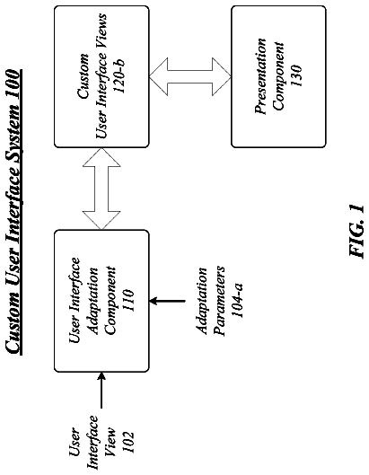
Techniques to customize a user interface for different displays
Techniques to customize a user interface for different displays are described.
US 9,864,654 B2 · Assignee: SanDisk Technologies LLC · Inventors: Vishne; Gadi et al.
Sheet 1 of 7 from the published document. All sheets in the USPTO PDF
A data storage device includes a memory and a controller coupled to the memory. The memory is configured to store first data and second data. The controller is configured to unlock the first data using a first key, to unlock the second data using a second key, and to determine that the second data is indicated as being uncorrectable in response to unlocking the second data using the second key.
Storage devices enable users to store and retrieve data. Examples of storage devices include volatile memory devices and non-volatile memory devices. A non-volatile memory retains data after a power-down event. During operation, a controller of a storage device may use control information related to operation of a memory. For example, the controller may store one or more tables indicating parameters (e.g., read parameters or write parameters) associated with operation of the memory. In some circumstances, a large data size of the control information may slow operation of the storage device. For example, a large table of parameters may be written to the memory prior to a power-down event and may be read from the memory in response to a power-on event, which may consume time, memory space, power, and processing resources. Searching a large table for information also consumes time, power, a
1 of 7 drawing sheets so far from the published document, cropped to the drawing. Every sheet is in the USPTO PDF.
What the patent claimed, word for word. All of it is now free to use.
The present disclosure is generally related to data storage devices and more particularly to data reading and writing processes for data storage devices.
Storage devices enable users to store and retrieve data. Examples of storage devices include volatile memory devices and non-volatile memory devices. A non-volatile memory retains data after a power-down event. During operation, a controller of a storage device may use control information related to operation of a memory. For example, the controller may store one or more tables indicating parameters (e.g., read parameters or write parameters) associated with operation of the memory.
In some circumstances, a large data size of the control information may slow operation of the storage device. For example, a large table of parameters may be written to the memory prior to a power-down event and may be read from the memory in response to a power-on event, which may consume time, memory space, power, and processing resources. Searching a large table for information also consumes time, power, and processing resources of the storage device.
FIG. 1 is a diagram of a particular illustrative example of a system that includes a data storage device having a data unlocking engine.
FIG. 2 is a diagram illustrating particular aspects of an illustrative example of a data unlocking engine, such as the data unlocking engine of FIG. 1 .
FIG. 3 is a flow chart of a particular illustrative embodiment of a method of locking data at a data storage device.
FIG. 4 is a flow chart of a particular illustrative example of a method of processing locked data at a data storage device.
FIG. 5 is a block diagram of a particular illustrative embodiment of a non-volatile memory system.
FIG. 6 is a block diagram of a particular illustrative embodiment of a storage system including a plurality of the non-volatile memory systems of FIG. 5 .
FIG. 7 is a block diagram of a particular illustrative embodiment of a hierarchical storage system.
FIG. 8 is a block diagram of components of a particular illustrative embodiment of a controller.
FIG. 9 is a block diagram of components of a particular illustrative embodiment of a non-volatile memory die.
A data storage device may use a particular key to “lock” (e.g., scramble, encrypt, and/or randomize) data to indicate that the data is uncorrectable (e.g., to flag the data as being uncorrectable). For example, if a certain command is received from a device (e.g., a host device) to flag the data as being uncorrectable, the data storage device may lock the data using the particular key (e.g., instead of storing information in a table indicating that the data is to be flagged as uncorrectable). As another example, if the data storage device writes dummy data to a storage region (e.g., to “fill” the storage region), the data storage device may lock the dummy data with the particular key. The data may include “ambiguous” data that can be read successfully (or “unlocked”) using certain parameters (e.g., the particular key) and that cannot be unlocked using other parameters (e.g., “standard” parameters, such as a user data scrambling key, a user data encryption key, or another user data key) of the data storage device.
In response to reading the data during operation (e.g., based on a command from the device or in connection with another process), the data storage device may attempt to unlock the data using one or more keys (e.g., a user data key). If the one or more other keys fail to unlock the data, and if the particular key successfully unlocks the data, then a determination may be made that the data has been flagged as uncorrectable (e.g., that the data is intended to be uncorrectable and that no error has occurred). If none of the keys unlocks the data, the data storage device may detect occurrence of an uncorrectable error correcting code (UECC) error (e.g., that the data is intended to be correctable and that an error has occurred). Locking the data using the particular key enables the data storage device to avoid storing and accessing a table that indicates which data is flagged as uncorrectable.
Particular aspects of the disclosure are described below with reference to the drawings. In the description, common or similar features may be designated by common reference numbers. As used herein, “exemplary” may indicate an example, an implementation, and/or an aspect, and should not be construed as limiting or as indicating a preference or a preferred implementation.
Referring to FIG. 1 , a particular illustrative example of a system is depicted and generally designated 100 . The system 100 includes a data storage device 102 and a device 170 (e.g., a host device or an access device).
The data storage device 102 includes a memory device 103 . The memory device 103 may include one or more memory dies (e.g., one memory die, two memory dies, sixty-four memory dies, or another number of memory dies).
The memory device 103 includes a memory 104 , such as a non-volatile array of storage elements included in a memory die or a volatile memory. The memory 104 may include a flash memory (e.g., a NAND flash memory) or a resistive memory, such as a resistive random access memory (ReRAM), as illustrative examples. The memory 104 may have a three-dimensional (3D) memory configuration. As used herein, a 3D memory device may include multiple physical levels of storage elements (instead of having a single physical level of storage elements, as in a planar memory device). As an example, the memory 104 may have a 3D vertical bit line (VBL) configuration. In a particular implementation, the memory 104 is a non-volatile memory having a 3D memory array configuration that is monolithically formed in one or more physical levels of arrays of memory cells having an active area disposed above a silicon substrate. Alternatively, the memory 104 may have another configuration, such as a two-dimensional (2D) memory configuration or a non-monolithic 3D memory configuration (e.g., a stacked die 3D memory configuration).
The memory 104 includes one or more regions of storage elements, such as a first storage region 111 , a second storage region 112 , and a third storage region 113 . An example of a storage region is a memory die. Another example of a storage region is a block, such as a NAND flash erase group of storage elements, or a group of resistance-based storage elements in a ReRAM implementation. Another example of a storage region is a word line of storage elements (e.g., a word line of NAND flash storage elements or a word line of resistance-based storage elements). A storage region may have a single-level-cell (SLC) configuration, a multi-level-cell (MLC) configuration, or a tri-level-cell (TLC) configuration, as illustrative examples. Each storage element of the memory 104 may be programmable to a state (e.g., a threshold voltage in a flash configuration or a resistive state in a resistive memory configuration) that indicates one or more values. As an example, in an illustrative TLC scheme, a storage element may be programmable to a state that indicates three values. As an additional example, in an illustrative MLC scheme, a storage element may be programmable to a state that indicates two values.
The memory 104 further includes a controller 130 coupled to the memory device 103 . The controller 130 may include a data locking engine 132 , a data unlocking engine 134 , a compaction engine 142 , and an interface 148 . In some implementations, the controller 130 may also include an error correcting code (ECC) engine (e.g., one or more encoders and one or more decoders).
The data locking engine 132 may include one or more of a scrambler, an encryption engine, a randomizer configured to randomize information, another component or module, or a combination thereof. The data unlocking engine 134 may include one or more of a descrambler, a decryption engine, a de-randomizer configured to de-randomize information, another component or module, or a combination thereof. In some implementations, functions described with reference to the data locking engine 132 and the data unlocking engine 134 may be performed by a single component of the controller 130 . As a non-limiting illustrative example, the controller 130 may be configured to perform symmetric key encryption and decryption using a common component of the controller 130 .
The controller 130 may store a table 136 and multiple keys. For example, the multiple keys may include a first key 138 and a second key 140 . Although FIG. 1 depicts two keys 138 , 140 for illustration, it should be appreciated that the controller 130 may use more than two keys. In some implementations, the first key 138 corresponds to a user data key that is reserved for user data, and the second key 140 corresponds to a write uncorrectable (W/U) data key that is reserved to flag information as being uncorrectable. The first key 138 may include one or more scrambling keys, a symmetric encryption key, multiple asymmetric encryption keys (e.g., an encryption key and a corresponding decryption key), one or more read parameters, one or more other parameters, or a combination thereof. The second key 140 may include one or more scrambling keys, a symmetric encryption key, multiple asymmetric encryption keys (e.g., an encryption key and a corresponding decryption key), one or more read parameters, one or more other parameters, or a combination thereof.
The data storage device 102 and the device 170 may be coupled via a connection, such as a bus, a wireless connection, a network connection, or another connection. The connection may be a bus interface, such as a serial advanced technology attachment (SATA) or peripheral component interface express (PCIe) interface. In one embodiment, the bus interface may be a non-volatile memory express (NVMe) or fiber channel over Ethernet (FCoE) interface. The system 100 may correspond to a solid state drive (SSD), such as found in computing devices, such as laptop computers, and tablet computers. In some implementations, the system 100 , the data storage device 102 , or the memory 104 may be integrated within a network-accessible data storage system, such as an enterprise data system, a network-attached storage (NAS) system, or a cloud data storage system, as illustrative examples.
During operation, the data storage device 102 is configured to receive data and instructions from the device 170 using an interface 148 . For example, the controller 130 may receive data 172 (e.g., user data) from the device 170 via the interface 148 . The controller 130 may receive a request for write access to the memory 104 from the device 170 , and the request may include the data 172 . The controller 130 may be configured to perform one or more other operations, such as “maintenance” operations. For example, the controller 130 may be configured to perform one or more memory management functions, such as wear leveling (distributing writes to avoid wearing out specific storage regions that would otherwise be repeatedly written to) and garbage collection (after a storage region is full, moving only the valid pages of data to a new storage region, so the full storage region can be erased and reused).
In response to receiving the data 172 from the device 170 , the controller 130 may input the data 172 to the data locking engine 132 . For example, the controller 130 may lock data (e.g., scramble or encrypt the data) in connection with write processes to reduce errors and/or increase data security at the data storage device 102 (e.g., prior to or after encoding the data by an ECC engine of the controller 130 ). The data locking engine 132 may lock the data 172 (e.g., using the first key 138 ) to generate first data 121 (e.g., prior to or after encoding the data 172 by an ECC engine of the controller 130 ). For example, the data locking engine 132 may scramble the data 172 , encrypt the data 172 , randomize the data 172 , perform one or more other operations, or a combination thereof. The first key 138 may correspond to one or more “default” or “standard” parameters that are used to lock (e.g., scramble or encrypt) user data prior to writing user data to the memory 104 .
In response to the data locking engine 132 locking the data 172 to generate the first data 121 , the controller 130 may initiate a write process to write the first data 121 to the memory 104 . For example, the controller 130 may send the first data 121 to the memory device 103 with a command to write the first data 121 to one or more physical addresses of the memory 104 .
The controller 130 may initiate a read process to read the first data 121 . For example, the controller 130 may initiate the read process in response to receiving a request for read access to the first data 121 from the device 170 . As another example, the controller 130 may initiate the read process in response to an “internal” event (e.g., a maintenance event), such as in connection with a compaction process initiated by the compaction engine 142 .
In response to initiating the read process, the controller 130 may send a command to the memory device 103 to read the first data 121 . The memory device 103 may sense the first data 121 and may provide the first data 121 (or a representation of the first data 121 ) to the controller 130 in response to the command.
The controller 130 may input the first data 121 to the data unlocking engine 134 to unlock the first data 121 . For example, the data unlocking engine 134 may use the first key 138 to descramble the first data 121 , to decrypt the first data 121 , to de-randomize the first data 121 , to perform one or more other operations, or a combination thereof. In some implementations, the controller 130 may input the first data 121 to an ECC engine of the controller 130 to decode the first data 121 prior to or after unlocking the first data 121 using the data unlocking engine 134 .
In some circumstances, the controller 130 may indicate (e.g., “flag”) data as being uncorrectable or may indicate a storage region of the memory 104 as storing uncorrectable data. For example, a protocol used by the data storage device 102 to communicate with the device 170 may define a request 150 . The request 150 may include an opcode, such as a write uncorrectable (W/U) data opcode 152 , and may further specify one or more logical addresses 154 . The W/U data opcode 152 may indicate that the controller 130 has associated the one or more logical addresses 154 with W/U data. For example, the W/U data opcode 152 may indicate that the controller 130 is to provide a message 156 (e.g., an error message) in response to receiving a request for read access from the device 170 to data associated with the one or more logical addresses 154 . To further illustrate, in some protocols, the request 150 may be used to verify operation of the data storage device 102 , such as by enabling verification of certain operations that are to result in an error message, such as the message 156 . Depending on the particular protocol, the request 150 may include information such as dummy data 144 to be written to the memory 104 in response the request 150 . In other cases, the request 150 may not include such information. For example, in some implementations, the controller 130 may generate information (e.g., the dummy data 144 ) in response to the request 150 , such as using a pseudo-random number generator (PRNG) of the controller 130 , as an illustrative example.
Alternatively or in addition, the controller 130 may flag data or a storage region of the memory 104 in connection with one or more other operations. As an example, the controller 130 may write dummy data to the second storage region 112 of the memory 104 , such as after closing the second storage region 112 to write operations (e.g., in response to a threshold number of program/erase (P/E) cycles at the second storage region 112 ). As another example, dummy data may be written to the memory 104 in connection with a compaction process initiated by the compaction engine 142 . The compaction process may include copying data from the first storage region 111 to the second storage region 112 (or vice versa). In these examples, the controller 130 may flag the dummy data as being uncorrectable (e.g., to avoid maintaining a table indicating memory locations of dummy data).
The controller 130 may initiate a process to flag information (e.g., the dummy data 144 ) as being uncorrectable. For example, the controller 130 may input the dummy data 144 to the data locking engine 132 . The data locking engine 132 may lock dummy data 144 (e.g., using the second key 140 ) to generate second data 122 . For example, the data locking engine 132 may scramble the dummy data 144 , encrypt the dummy data 144 , randomize the dummy data 144 , perform one or more other operations, or a combination thereof.
In response to locking the dummy data 144 to generate the second data 122 , the controller 130 may initiate a write process to write the second data 122 to the memory 104 (e.g., in response to receiving the request 150 from the device 170 or in connection with another process, such as a compaction process). For example, the controller 130 may be configured to write the second data 122 to the memory device 103 with a command to write the second data 122 to one or more physical addresses of the memory 104 .
The controller 130 may initiate a read process to access the second data 122 . For example, the controller 130 may initiate the read process in response to receiving a read request 160 for read access to the second data 122 from the device 170 . The read request 160 may include a read opcode 162 and may identify the one or more logical addresses 154 . As another example, the controller 130 may initiate the read process in response to an “internal” event (e.g., a maintenance event), such as in connection with a compaction process initiated by the compaction engine 142 .
In response to initiating the read process, the controller 130 may send a command to the memory device 103 to read the second data 122 . The memory device 103 may sense the second data 122 and may provide the second data 122 (or a representation of the second data 122 ) to the controller 130 in response to the command.
The controller 130 may input the second data 122 to the data unlocking engine 134 to unlock the second data 122 . For example, the data unlocking engine 134 may attempt to unlock the second data 122 using the first key 138 . Because the second data 122 is locked using the second key 140 (instead of the first key 138 ), use of the first key 138 fails to unlock the second data 122 . In some implementations, the first key 138 fails to unlock the second data 122 if one or more conditions are unsatisfied upon applying the first key 138 to the second data 122 , such as if the second data 122 fails to satisfy one or more parity conditions, one or more error correction conditions, and/or one or more hash conditions associated with the first key 138 . To further illustrate, a signature may be generated based on (or extracted from) the second data 122 , as described further with reference to FIG. 2 .
In response to failing to unlock the second data 122 using the first key 138 , the data unlocking engine 134 may use the second key 140 to unlock the second data 122 . For example, the data unlocking engine 134 may use the second key 140 to descramble the second data 122 , to decrypt the second data 122 , to de-randomize the second data 122 , to perform one or more other operations, or a combination thereof.
In response to unlocking the second data 122 using the second key 140 , the controller 130 may determine that the second data 122 is indicated as being uncorrectable (e.g., that the second data 122 is intended to be uncorrectable). For example, the controller 130 may determine that the second data 122 was written to the memory 104 in response to a request (e.g., the request 150 ) to program W/U data to the memory 104 and/or that the second data 122 includes dummy data.
If the read process to read the second data 122 is performed in response to the request 150 , the controller 130 may be configured to send a message (e.g., the message 156 ) to the device 170 in response to determining that the second data 122 is indicated as being uncorrectable. The message 156 may indicate that data corresponding to the one or more logical addresses 154 is uncorrectable. To illustrate, the message 156 may include a particular sequence of bit values (e.g., a sequence of logic zero bits) indicating an error, such as a W/U data error.
In some cases, the data unlocking engine 134 may fail to unlock data using both the first key 138 and the second key 140 . To illustrate, the controller 130 may initiate a read process to read third data 123 (e.g., in response to a request from the device 170 , or in response to another event, such as initiation of a compaction process). The controller 130 may receive the third data 123 (or a representation of the third data 123 ) from the memory device 103 and may input the third data 123 to the data unlocking engine 134 . In some implementations, the first key 138 and the second key 140 may fail to unlock the third data 123 if one or more conditions are unsatisfied upon applying the first key 138 and the second key 140 to the third data 123 . For example, if applying the first key 138 and the second key 140 to the third data 123 fails to satisfy one or more parity conditions, one or more error correction conditions, and/or one or more hash conditions, then the first key 138 and the second key 140 fail to unlock the third data 123 . To further illustrate, a signature may be generated based on (or extracted from) the third data 123 , as described further with reference to FIG. 2 .
If the data unlocking engine 134 fails to unlock the third data 123 using the first key 138 and also fails to unlock the third data 123 using the second key 140 , the controller 130 may determine that an uncorrectable error correcting code (UECC) event has occurred (e.g., that the third data 123 is unintentionally uncorrectable). Depending on the particular circumstances, the third data 123 may include user data or dummy data that has been corrupted (e.g., by a hardware error or by a disturb effect, as illustrative examples).
In response to detecting the UECC event, the controller 130 may update the table 136 . For example, the controller 130 may update a number of UECC events associated with the third storage region 113 . If a number of UECC events associated with a particular storage region of the memory 104 satisfies a threshold number of UECC events, the controller 130 may detect a physical defect associated with the particular storage region and may close the particular storage region to write operations. For example, if the UECC event associated with the third data 123 causes the number of UECC events associated with the third storage region 113 to satisfy the threshold number of UECC events, the controller 130 may close the third storage region 113 to write operations. In this case, valid data stored at the third storage region 113 may be copied to another storage region of the memory 104 (e.g., to the first storage region 111 , as an illustrative example).
The examples of FIG. 1 enable the data storage device 102 to avoid maintaining and searching one or more tables to identify data flagged as being uncorrectable. Therefore, performance of the data storage device 102 may be improved by increasing read process speed (e.g., since the second key 140 may be used relatively infrequently) and by reducing an amount of storage space of the data storage device 102 used to store one or more tables.
FIG. 2 depicts certain aspects of an illustrative example of the data unlocking engine 134 of FIG. 1 . The illustrative example of FIG. 2 depicts that the data unlocking engine 134 may include a front-end component 208 , a signature generator 216 that is coupled to the front-end component 208 , and a signature verifier 224 that is coupled to the front-end component 208 and to the signature generator 216 . The data unlocking engine 134 may also include a message generator 228 and a UECC indication generator 232 . The message generator 228 and the UECC indication generator 232 may be coupled to the signature verifier 224 .
During operation, the controller 130 of FIG. 1 may provide data 204 to the front-end component 208 of the data unlocking engine 134 (e.g., upon reading the data 204 from the memory 104 of FIG. 1 ). Depending on the particular example, the data 204 may include the first data 121 , the second data 122 , the third data 123 , or other data. The data 204 may include scrambled data, encrypted data, randomized data, other data, or a combination thereof.
The front-end component 208 may be configured to perform one or more operations in response to receiving the data 204 . For example, the front-end component 208 may be configured to apply the first key 138 to the data 204 to generate information 212 . Applying the first key 138 may include descrambling the data 204 based on the first key 138 , decrypting the data 204 based on the first key 138 , de-randomizing the data 204 based on the first key 138 , performing one or more other operations, or a combination thereof. As a particular illustrative example, the front-end component 208 may include a hardware decryption circuit configured to decrypt the data 204 (or to attempt to decrypt the data 204 ) using the first key 138 .
The signature generator 216 may be configured to receive the information 212 from the front-end component 208 . The signature generator 216 may be configured to generate (or extract) a signature 220 based on the information 212 . The signature 220 may be generated based on one or more parity conditions, one or more error correction conditions, or a combination thereof. As an illustrative non-limiting example, a parity condition or an error correction condition may specify a particular number of logic zero bits of user data, a particular number of logic one bits of user data, or a combination thereof. In this example, the signature 220 may include a value indicating a number of logic zero bits of the information 212 , a number of logic one bits of the information 212 , or a combination thereof. Alternatively or in addition, the signature 220 may include error information associated with the information 212 . For example, in some ECC schemes, a number of errors, one or more error locations, and/or bit error rate (BER) associated with the information 212 may be estimated (e.g., either with or without performing a “full” decoding process of the data 204 ), such as by counting a number and/or bit position of particular bits or bit sequences. Alternatively or in addition, the signature 220 may include a hash value associated with the information 212 . In this example, the signature generator 216 may include a hash function circuit configured to determine a hash value of the information 212 based on a hash function.
The signature verifier 224 may be configured to determine whether the signature 220 indicates that the data 204 has been unlocked successfully (e.g., based on whether the information 212 satisfies one or more parity conditions, one or more error correction conditions, one or more hash conditions, one or more other conditions, or a combination thereof). For example, the signature 220 may include parity information, and the signature verifier 224 may be configured to determine whether the parity information “matches” the information 212 . Alternatively or in addition, the signature 220 may indicate error information (e.g., a number of errors, one or more error locations, or a BER) associated with the information 212 , and the signature verifier 224 may be configured to determine whether the error information satisfies an error threshold. Alternatively or in addition, the signature 220 may include a hash value, and the signature verifier 224 may be configured to determine whether the hash value is “correct” (e.g., by comparing the hash value to one or more reference hash values).
If the signature verifier 224 determines based on the signature 220 that the data 204 has been unlocked successfully, the data unlocking engine 134 may output the information 212 . Depending on the particular example, the information 212 may be provided to the device 170 of FIG. 1 (e.g., in response to the read request 160 ), to the memory device 103 (e.g., in connection with a compaction operation initiated by the compaction engine 142 ), or to another component or module of the controller 130 . In this example, the data 204 may include the first data 121 of FIG. 1 .
If the signature verifier 224 determines based on the signature 220 that the data 204 has not been unlocked successfully, the signature verifier 224 may provide an indication to the front-end component 208 that the signature 220 does not “match” the information 212 . In response to the indication, the front-end component 208 may apply the second key 140 to the data 204 . For example, the front-end component 208 may generate second information 242 and may provide the second information 242 to the signature generator 216 . The signature generator 216 may generate a second signature 250 based on the second information 242 and may provide the second signature 250 to the signature verifier 224 . The signature verifier 224 may compare the second signature 250 and the second information 242 to determine whether the second signature 250 indicates that the data 204 has been successfully unlocked using the second key 140 .
If the signature verifier 224 determines based on the second signature 250 that the data 204 has been successfully unlocked using the second key 140 , the data unlocking engine 134 may determine that the data 204 is indicated as being uncorrectable. For example, if the second key 140 is reserved for flagging data as being uncorrectable, then successfully unlocking the data 204 using the second key 140 may indicate that the data 204 has been flagged as being uncorrectable. Depending on the particular example, upon detecting that the data 204 is flagged as being uncorrectable, the controller 130 may provide the message 156 to the device 170 in response to receiving the read request 160 , or the controller 130 may perform one or more other operations (e.g., operations associated with a compaction process initiated by the compaction engine 142 ). To further illustrate, the signature verifier 224 may output a control signal causing the message generator 228 to generate the message 156 or another message, such as a message provided to the compaction engine 142 indicating that the data 204 is indicated as being uncorrectable.
Alternatively, if the signature verifier 224 determines based on the second signature 250 that the data 204 has not been successfully unlocked using the second key 140 , the data unlocking engine 134 may determine that an unrecoverable error (e.g., a UECC error) has occurred. In this case, the signature verifier 224 may provide a control signal to the UECC indication generator 232 , and the UECC indication generator 232 may output an indication of the UECC error. In some implementations, the controller 130 may update the table 136 in response to the UECC indication provided by the UECC indication generator 232 (e.g., to track a number of UECC errors at the memory 104 in order to detect one or more physical defects or hardware errors).
Although the second key 140 has been described in terms of a single key, it should be appreciated that certain implementations may utilize multiple keys corresponding to the second key 140 . For example, the data unlocking engine 134 may utilize multiple keys to determine an error type (e.g., an error “severity”) associated with the data 204 , such as if the second key 140 corresponds to a plurality of keys representing a range of error types (e.g., a low error severity, a moderate error severity, and a high error severity). In this example, the data unlocking engine 134 may attempt to unlock the data 204 using a first particular key of the plurality of keys. If the data unlocking engine 134 determines (e.g., based on the signature 220 ) that the first particular key successfully unlocks the data 204 , then the data unlocking engine 134 may detect a low error severity associated with the data 204 . If the data unlocking engine 134 fails to unlock the data 204 using the first particular key, the data unlocking engine 134 may attempt to unlock the data 204 using a second particular key of the plurality of keys.
If the data unlocking engine 134 unlocks the data 204 using the second particular key (and fails to unlock the data 204 using the first particular key), the data unlocking engine 134 may detect a moderate error severity associated with the data 204 . Alternatively, if the data unlocking engine 134 fails to unlock the data 204 using the first particular key and the second particular key, the data unlocking engine 134 may detect a high error severity associated with the data 204 . In some implementations, the controller 130 may update the table 136 based on the error severity (e.g., to track a number and/or severity of errors in order to detect one or more physical defects or hardware errors associated with the memory 104 ). Further, although two keys corresponding to the second key 140 have been described, it should be appreciated that the plurality of keys may include another number of keys (e.g., three keys, four keys, or another number of keys).
The example of FIG. 2 may improve performance of a data storage device. For example, a data storage device may avoid maintaining and searching one or more tables to identify data flagged as being uncorrectable (e.g., by using the second key 140 to identify data indicated as being uncorrectable instead of using a table).
Referring to FIG. 3 , a particular illustrative example of a method is depicted and generally designated 300 . The method 300 may be performed at a data storage device, such as at the data storage device 102 of FIG. 1 .
The method 300 may include locking data using a first key to generate first data, at 302 . For example, the data 172 may be locked using the first key 138 to generate the first data 121 . To further illustrate, the first key 138 may include one or more scrambling keys, a symmetric encryption key, multiple asymmetric encryption keys, and/or one or more other parameters.
The method 300 may further include writing the first data to a first storage region of a memory, at 304 . As an example, the first data 121 may be written to the first storage region 111 of the memory 104 .
The method 300 may further include determining to indicate second data as being uncorrectable, at 306 . For example, the request 150 of FIG. 1 may indicate that the data storage device 102 is to return a message (e.g., the message 156 ) indicating that the second data 122 is uncorrectable in response to a request for read access to the second data 122 (e.g., in response to the read request 160 ). As another example, a process may include writing information (e.g., dummy data) to the memory 104 that is to be flagged as being uncorrectable (e.g., in connection with a compaction process).
The method 300 may further include locking data using a second key to generate the second data, at 308 . For example, the dummy data 144 may be locked using the second key 140 to generate the second data 122 (so that the second data 122 cannot be read using default parameters (e.g., the first key 138 ) but can be read using the second key 140 ).
The method 300 may further include writing the second data to a second storage region of the memory, at 310 . For example, the second data 122 may be written to the second storage region 112 of the memory 104 in connection with the method 300 of FIG. 3 .
The method 300 of FIG. 3 may improve performance of a data storage device. For example, the method 300 may enable a data storage device to flag data as being uncorrectable without use of one or more tables to identify data flagged as being uncorrectable, which may be large and which may consume storage space of a data storage device.
Referring to FIG. 4 , a particular illustrative example of a method is depicted and generally designated 400 . The method 400 may be performed at a data storage device, such as at the data storage device 102 of FIG. 1 .
The method 400 may include receiving data from the memory, at 402 . For example, the controller 130 of FIG. 1 may receive any of the first data 121 , the second data 122 , the third data 123 , or the data 204 from the memory 104 .
The method 400 may further include determining (e.g., using the signature verifier 224 of FIG. 2 ) whether the data unlocks using a first key, at 404 . For example, the first key may correspond to the first key 138 , and the data unlocking engine 134 may be configured to attempt to unlock the data using the first key 138 .
If the data is unlocked using the first key, then a determination may be made that the data is read successfully, at 406 . In this case, the data may include the first data 121 , as an illustrative example. The data unlocking engine 134 may be configured to determine that the data is read successfully if the data is unlocked using the first key 138 .
If the first key fails to unlock the data, then the method 400 may further include determining (e.g., using the signature verifier 224 of FIG. 2 ) whether the data unlocks using a second key, at 408 . For example, the second key may correspond to the second key 140 , and the data unlocking engine 134 may be configured to use the second key 140 in response to failing to unlock the data using the first key 138 .
If the data is unlocked using the second key, then a determination may be made that the data is flagged as being uncorrectable, at 410 . In this case, the data may include the second data 122 , as an illustrative example. The method 400 may optionally include sending the message 156 to the device 170 to indicate that the data is uncorrectable.
If the second key fails to unlock the data, then the method 400 may further include detecting a UECC error, at 412 . In this case, the data may include the third data 123 , as an illustrative example. In some circumstances, the UECC error may result from a hardware error or physical defect of the memory 104 . The method 400 may optionally include updating the table 136 to indicate the UECC error (e.g., to track a number of UECC errors at a particular storage region of the memory 104 to enable the controller 130 to detect a hardware error or a physical defect associated with the particular storage region).
The method 400 may improve performance of a data storage device. For example, the method 400 may enable a data storage device identify data indicated as being uncorrectable (e.g., W/U data) without storing and accessing a table that indicates the data as being uncorrectable. Thus, available memory space may be increased.
The description continues in the full USPTO document.
About 6,849 words. The USPTO PDF has it with every drawing.
Fees are due 3.5, 7.5 and 11.5 years after grant. This patent expired on January 9, 2026, so the fee marked "not paid" was the one that went unpaid.
DETECTING DATA INDICATED AS BEING UNCORRECTABLE AT A DATA STORAGE DEVICE
Filed Sep 2015 · published Mar 2017Detecting data indicated as being uncorrectable at a data storage device
Filed Sep 2015 · granted Jan 2018Earlier publications, parents and continuations. None of them can still be enforced, or this patent would not be listed.
Prior art cited by the examiner or applicant. Useful when you check your own idea for novelty.
Everything on this page comes from the documents linked above.