 Lapsed, fee not paid7 drawings
Vehicles & Drones · US 9,863,367 B2
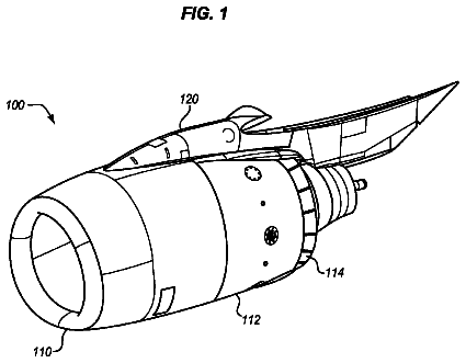
Fan nozzle drive systems that lock thrust reversers
Systems and methods are provided that lock thrust reversers and also drive fan nozzles of an aircraft.
US 9,863,372 B2 · Assignee: Mazda Motor Corporation · Inventors: Fujimoto; Masahiko et al.
Sheet 1 of 11 from the published document. All sheets in the USPTO PDF
A control apparatus of a premixed charge compression ignition engine that includes an engine body having a cylinder and intake and exhaust passages, and causes a mixture gas to self-ignite inside the cylinder is provided. The apparatus includes a fuel injector for injecting fuel into the cylinder, a water injector for injecting supercritical water or subcritical water into the cylinder, an EGR passage for communicating the exhaust and intake passages and recirculating, as EGR gas, a portion of an exhaust gas discharged from the cylinder to the intake passage, an EGR valve for adjusting an EGR gas recirculation amount, and a controller. The controller includes an engine load determining module for receiving a parameter and determining whether an engine operating state is a first state where the engine load is below a switch load or a second state where the engine load is the switch load or above.
The present invention relates to a control apparatus of a premixed charge compression ignition engine, which includes an engine body having a cylinder in which mixture gas self-ignites within at least one of operating ranges of the engine. Conventionally, a study is conducted about performing premixed charge compression ignition combustion in the engine, in order to improve fuel consumption. In the premixed charge compression self-ignition combustion, fuel and air are premixed to form a mixture gas and the mixture gas is compressed to self-ignite. However, for example, when an engine load is high, an issue of producing more smoke arises due to the mixture gas igniting before the fuel is sufficiently mixed with air, and further, an issue of worsening combustion noise arises due to an increase in pressure inside the cylinder of the engine. In this regard, a study is conducted about perform
1 of 11 drawing sheets so far from the published document, cropped to the drawing. Every sheet is in the USPTO PDF.
What the patent claimed, word for word. All of it is now free to use.
The present invention relates to a control apparatus of a premixed charge compression ignition engine, which includes an engine body having a cylinder in which mixture gas self-ignites within at least one of operating ranges of the engine.
Conventionally, a study is conducted about performing premixed charge compression ignition combustion in the engine, in order to improve fuel consumption. In the premixed charge compression self-ignition combustion, fuel and air are premixed to form a mixture gas and the mixture gas is compressed to self-ignite.
However, for example, when an engine load is high, an issue of producing more smoke arises due to the mixture gas igniting before the fuel is sufficiently mixed with air, and further, an issue of worsening combustion noise arises due to an increase in pressure inside the cylinder of the engine.
In this regard, a study is conducted about performing Exhaust Gas Recirculation (EGR) in which EGR gas (a portion of the exhaust gas) is recirculated to an intake passage, to introduce an inactive gas which is neither fuel nor air into the cylinder. In this manner, an ignition delay time of the mixture gas is extended, and as a result, the mixing of the fuel and air is stimulated. JP2009-209809A discloses such an art.
However, there is a limit to the extending effect of the ignition delay time which can be obtained by introducing the EGR gas, and within an engine operating range where an engine load is high, it becomes difficult to secure a suitable length of ignition delay time by the EGR gas introduction. Specifically, within the operating range where the engine load is high, since an amount of air required for combustion becomes large, to recirculate a large amount of EGR gas while securing the air amount, a forced induction needs to be performed, which increases pressure inside the cylinder. However, the ignition delay time becomes shorter as the pressure inside the cylinder increases. Therefore, within this operating range, even if the large amount of EGR gas is recirculated, the ignition delay time may not be extended sufficiently.
The present invention is made in view of the above situations and aims to provide a control apparatus of a premixed charge compression ignition engine, which is capable of extending an ignition delay time more reliably.
According to one aspect of the present invention, a control apparatus of a premixed charge compression ignition engine that includes an engine body having a cylinder, an intake passage, and an exhaust passage, and causes a mixture gas to self-ignite inside the cylinder, is provided. The apparatus includes a fuel injector for injecting fuel into the cylinder, a water injector for injecting one of supercritical water and subcritical water into the cylinder in a period from a latter half of compression stroke and an early half of expansion stroke, an EGR passage for communicating the exhaust passage with the intake passage and recirculating, as EGR gas, a portion of the exhaust gas discharged from the cylinder to the intake passage, an EGR valve for adjusting an amount of the EGR gas recirculating to the intake passage through the EGR passage, and a controller for controlling various parts of the engine, the various parts including the water injector and the EGR valve. The controller includes an engine load determining module for receiving a parameter of a load of the engine that varies based on an accelerator opening, and determining whether an operating state of the engine body is a first state where the engine load is below a predetermined switch load or a second state where the engine load is the predetermined switch load or above. When the operating state is determined to be the first state by the engine load determining module, the controller outputs control signals to the EGR valve and the water injector, the control signals causing the EGR valve to introduce the EGR gas into the cylinder, and causing an injection amount of the one of the supercritical water and the subcritical water to be smaller than an introduction amount of the EGR gas into the cylinder. When the operating state is determined to be the second state, the controller outputs control signals to the EGR valve and the water injector, the control signals causing the water injector to inject the one of the supercritical water and the subcritical water into the cylinder, and causing the introduction amount of the EGR gas into the cylinder to be smaller than the injection amount of the one of the supercritical water and the subcritical water.
According to this configuration, in both the first and second states, a sufficient length of ignition delay time can be secured and, thus, an increase in production of smoke, and a sharp increase in pressure inside the cylinder which results in increasing combustion noise, can be reduced. As a result, more suitable premixed charge compression self-ignition combustion can be achieved.
Specifically, when the engine load is low, the ignition delay time can be extended mainly by introducing the EGR gas. On the other hand, when the engine load is high, which easily causes the issues of increase in production of smoke and combustion noise, a large amount of water which is a substance other than fuel and air (hereinafter, may be referred to as an “inactive substance”), is directly introduced into the cylinder and the introduction amount of the EGR gas into the cylinder is reduced. Therefore, while reliably securing the sufficient length of ignition delay time by introducing the large amount of the inactive substance into the cylinder, a sufficient amount of air can be introduced into the cylinder without a forced induction compared to a case where the inactive substance consists only of the EGR gas. As a result, an engine output can be secured.
Further, in the above configuration, the one of the supercritical water and the subcritical water is used as the water, and this supercritical water etc. is injected into the cylinder when pressure and temperature of the cylinder are high, which is between the latter half of the compression stroke and the early half of the expansion stroke, so that the water remains inside of the cylinder in a state of the one of the supercritical water and the subcritical water before the ignition of the mixture gas. Therefore, the ignition delay time can be extended more reliably while reducing energy loss.
Specifically, the supercritical water and the subcritical water have higher densities than water in a normal gas phase (water vapor). Therefore, by injecting the one of the supercritical water and the subcritical water, a large amount of water can efficiently be introduced into the cylinder compared to injecting the water in the gas phase. Thus, an oxygen concentration inside the cylinder can be sufficiently decreased and the ignition delay time can be extended more reliably. Additionally, water in a liquid phase requires latent heat to become water vapor, whereas the supercritical water and the subcritical water either do not require latent heat at all or require only low latent heat. Therefore, in a case of injecting the water in the liquid phase into the cylinder, the temperature inside the cylinder may significantly decrease due to water vaporization of the injected water, and thermal efficiency may degrade. In this regard, in the case of injecting the one of the supercritical water and the subcritical water into the cylinder, such significant temperature reduction and thermal efficiency degradation can be avoided. Therefore, while injecting the one of the supercritical water and the subcritical water in an amount that is large enough to sufficiently secure the ignition delay time, the thermal efficiency can be kept high.
Note that, in the present invention, the latter half of the compression stroke is a period between 90° CA (crank angle) before a top dead center of the compression stroke (CTDC) and the CTDC, and the early half of the expansion stroke is a period between the CTDC and 90° CA after the CTDC.
In the above configuration, a geometric compression ratio of the engine body may be set to be between 18:1 and 35:1. An effective compression ratio of the engine body when the engine load may be the switch load or above is set to be between 15:1 and 30:1.
Thus, in the second state, a high engine torque can be secured with the large effective compression ratio while achieving the suitable premixed charge compression self-ignition combustion as described above.
Further, in the above configuration, when the operating state is the second state, the controller may set an air excess ratio to be 1 or below at least while the engine load is high in the second state, and the controller may stop the introduction of the EGR gas into the cylinder at least while the engine load is high in the second state.
In this manner, in a case where the air excess ratio is 1 or below and the ignition delay time easily becomes short, the ignition delay time can be extended more reliably.
Further, in the above configuration, the control apparatus may further include a water processing device for generating the one of the supercritical water and the subcritical water. The water processing device may include a condenser for condensing water vapor contained within the exhaust gas discharged from the engine body, and a heater and compressor for increasing the condensed water vapor in temperature and pressure by supplying thermal energy of the exhaust gas to the condensed water vapor.
With the above configuration, the one of the supercritical water and the subcritical water can be generated by using water vapor within the exhaust gas and thermal energy of the exhaust gas. Therefore, energy efficiency can be improved compared to a case of separately providing a device for generating the water. Note that when the engine load is low, since a temperature of the exhaust gas, in other words, thermal energy of the exhaust gas, is low, it may not be able to generate a large amount of the one the supercritical water and the subcritical water. In this regard, with the above configuration in the first state, since the injection amount of the one of the supercritical water and the subcritical water is reduced and the large amount of the EGR gas is introduced, the ignition delay time can be secured while increasing the thermal efficiency.
Moreover, according to the present invention, the suitable premixed charge compression self-ignition combustion can be achieved more reliably as described above. Therefore, it is effective to apply the present invention to a gasoline engine with which it is comparatively difficult to perform premixed charge compression self-ignition combustion. Thus, the fuel may contain gasoline.
FIG. 1 is a view illustrating a configuration of an engine system according to one embodiment of the present invention.
FIG. 2 is a water phase diagram illustrating supercritical water.
FIG. 3 is a water phase diagram illustrating subcritical water.
FIG. 4 is an enlarged cross-sectional view schematically illustrating a part of an engine body.
FIG. 5 is a cross-sectional view schematically illustrating a fuel injector.
FIG. 6 is a block diagram illustrating a control system of the engine.
FIG. 7 is a chart illustrating a control range of the engine.
FIG. 8 is a chart illustrating a relationship among an engine load, an EGR ratio, and a water injection ratio.
FIG. 9 shows charts illustrating an ignition delay time.
FIG. 10 shows charts illustrating contents of a control within a high engine load range.
FIG. 11A is a chart illustrating a relationship between the EGR ratio and a temperature of mixture gas, and FIG. 11B is a chart illustrating a relationship between the water injection ratio and the temperature of the mixture gas.
Overall Configuration of Engine System
FIG. 1 is a view illustrating a configuration of an engine system to which a control apparatus of a premixed charge compression ignition engine is applied, according to one embodiment of the present invention. The engine system of this embodiment includes an engine body 1 of a four stroke type, an intake passage 30 for introducing air for combustion into the engine body 1 , and an exhaust passage 40 for discharging the exhaust gas generated in the engine body 1 . The engine body 1 is, for example, a four-cylinder engine having four cylinders 2 . In this embodiment, the engine body 1 is driven by receiving fuel containing gasoline. The engine system of this embodiment is mounted on a vehicle, and the engine body 1 is used as a drive source of the vehicle.
The intake passage 30 is provided with, in the following order from its upstream side, an air cleaner 31 and a throttle valve 32 . The air passes through the air cleaner 31 and the throttle valve 32 and then is introduced into the engine body 1 .
The throttle valve 32 opens and closes the intake passage 30 . Note that, in this embodiment, while the engine is in operation, the throttle valve 32 is basically kept fully opened or nearly fully opened, and only in a limited operation condition (e.g., the engine is stopped) is the throttle valve 32 closed to block the intake passage 30 .
The exhaust passage 40 is provided with, in the following order from its upstream side, a three-way catalyst 41 for purifying the exhaust gas, a heat exchanger 42 (heater and compressor), a condenser 43 , and an exhaust shutter valve 44 . The heat exchanger 42 and the condenser 43 constitute a part of a later-described exhaust heat recovery device 60 (water processing device).
The exhaust shutter valve 44 stimulates a recirculation of the EGR gas to the intake passage 30 .
Specifically, with the engine system of this embodiment, an EGR passage 51 communicating a part of the intake passage 30 downstream of the throttle valve 32 and a part of the exhaust passage 40 upstream of the three-way catalyst 41 is formed, and a portion of the exhaust gas is recirculated as the EGR gas to the intake passage 30 . Further, the exhaust shutter valve 44 opens and closes the exhaust passage 40 . When the EGR is performed and pressure inside the exhaust passage 40 is low, an opening of the exhaust shutter valve 44 is narrowed to increase pressure inside an upstream part of the EGR passage 51 so as to stimulate the EGR gas recirculation.
The EGR passage 51 is provided with an EGR valve 52 (EGR gas amount adjuster) for opening and closing the EGR passage 51 , and an amount of the EGR gas recirculated to the intake passage 30 is controlled by adjusting an opening of the EGR valve 52 . Further in this embodiment, the EGR passage 51 is provided with an EGR cooler 53 for cooling the EGR gas passing therethrough, and the EGR gas is recirculated to the intake passage 30 after being cooled by the EGR cooler 53 .
The exhaust heat recovery device 60 generates supercritical water by using thermal energy of the exhaust gas. Specifically, with the engine system of this embodiment, the supercritical water is injected into the respective cylinders 2 from water injectors 22 as described later, and the supercritical water is generated by using the exhaust gas.
The exhaust heat recovery device 60 includes the heat exchanger 42 and the condenser 43 , and additionally a condensed water passage 61 , a water tank 62 , and a water injection pump 63 . The condensed water passage 61 connects the water injectors 22 with the condenser 43 .
The condenser 43 condenses water (water vapor) within the exhaust gas passing through the exhaust passage 40 . The water tank 62 stores the condensed water therein. The condensed water generated by the condenser 43 is introduced into the water tank 62 through the condensed water passage 61 and stored in the water tank 62 .
The water injection pump 63 sends the condensed water inside the water tank 62 to the water injectors 22 through the heat exchanger 42 . The condensed water inside the water tank 62 is increased in temperature and pressure by the water injection pump 63 when being sent. For example, the condensed water is increased to about 350 K in temperature and about 250 bar in pressure by the water injection pump 63 .
The heat exchanger 42 exchanges heat between the condensed water sent by the water injection pump 63 and the exhaust gas passing through the exhaust passage 40 . The heat exchanger 42 is an indirect heat exchanger, and the condensed water receives the thermal energy from the exhaust gas when passing through the heat exchanger 42 . By passing through the heat exchanger 42 , the condensed water is increased more in temperature and pressure from the state where pressure is applied thereto by the water injection pump 63 , and becomes supercritical water.
The supercritical water is water with a higher temperature and pressure than that at the critical point of water, and has a high density close to liquid while molecules move as actively as gas moves. In other words, the supercritical water is water which does not require latent heat for a phase change into gas or liquid. As is described later in detail, in this embodiment, by injecting the water with such properties into the cylinders 2 , a long ignition delay time is secured, and suitable premixed charge compression self-ignition combustion is achieved.
A specific description regarding this matter is given with reference to FIG. 2 . FIG. 2 is a water phase diagram of which a horizontal axis indicates enthalpy and a vertical axis indicates pressure. In FIG. 2 , an area Z 2 is an area of liquid, an area Z 3 is an area of gas, and an area Z 4 is a coexisting area of liquid and gas. Lines LT 350 , LT 400 , . . . , LT 1000 indicated by solid lines are isothermal lines, each formed by connecting points of the same temperature. The numbers of the lines indicate temperatures (K). For example, LT 350 is an isothermal line of 350 K, and LT 1000 is an isothermal line of 1,000 K. Further, a point X 1 is the critical point and an area Z 1 is an area where a temperature and pressure are higher than the critical point X 1 , and the supercritical water belongs to this area Z 1 . Specifically, while the critical point of water is at the temperature of 647.3K and the pressure of 22.12 MPa, the temperature and pressure of the supercritical water are the same or above, in other words, the temperature is 647.3K or above and the pressure is 22.12 MPa or above.
In FIG. 2 , lines LR 0 . 01 , LR 0 . 1 , . . . , LR 500 indicated by dashed lines are isopycnic lines, each formed by connecting points of the same density. The numbers of the lines indicate densities (kg/m.sup.3). For example, LR 0 . 01 is an isopycnic line of 0.01 kg/m.sup.3, and LR 500 is an isopycnic line of 500 kg/m.sup.3. As is apparent from comparisons of these isopycnic lines LR with the areas Z 1 and Z 3 , the density of the water within the area Z 1 , in other words, the supercritical water, is about from 50 kg/m.sup.3 to 500 kg/m.sup.3, which is close to that of water in the liquid phase and much higher than a density of gas.
Note that the supercritical water generated by the engine system and injected into the cylinders 2 preferably has a density of 250 kg/m.sup.3 or above.
Further, as indicated by an arrow Y 1 in FIG. 2 , water in a normal liquid phase requires a high enthalpy to become a gas. In other words, the water in the normal liquid phase requires comparatively high latent heat to change into gas. In this regard, as indicated by an arrow Y 2 , the supercritical water requires almost no enthalpy, in other words, latent heat, to become water in a normal gas phase.
Here, as is apparent from FIG. 2 , water belonging to an area near the area Z 1 has a high density and requires low latent heat to become gas, which are properties similar to the supercritical water. Therefore, although the supercritical water is generated by the exhaust heat recovery device 60 and injected into the cylinders 2 in this embodiment as described above, instead of the supercritical water, subcritical water which is water belonging to the area near the area Z 1 may be generated and injected into the cylinders 2 . For example, subcritical water within an area Z 10 where the temperature is 600 K or above and the density is 250 kg/m.sup.3 or above (see FIG. 3 ) may be generated and injected.
Structure of Engine Body
A structure of the engine body 1 is described next.
FIG. 4 is an enlarged cross-sectional view illustrating a part of the engine body 1 . As illustrated in FIG. 4 , the engine body 1 includes a cylinder block 3 formed therein with the cylinders 2 , a cylinder head 4 formed on the cylinder block 3 , and pistons 5 fitted into the cylinders 2 to be reciprocatable (in up-and-down directions), respectively.
A combustion chamber 6 is formed above each piston 5 . The combustion chamber 6 is a so-called pent-roof type, and a ceiling surface of the combustion chamber 6 (a bottom surface of the cylinder head 4 ) has a triangular roof shape formed by two inclining surfaces on an intake side and an exhaust side.
In this embodiment, to reduce a cooling loss by reducing release of heat of the combustion gas from the combustion chamber 6 to the outside of the combustion chamber 6 , wall surfaces (inner surfaces) of each combustion chamber 6 are provided with heat insulating layers 7 having lower thermal conductivity than the inner surfaces of the combustion chamber 6 . Specifically, the heat insulating layer 7 is provided to each of a wall surface of the cylinder 2 , a crown surface 5 a of the piston 5 , the bottom surface of the cylinder head 4 , and surfaces of valve heads of intake and exhaust valves 18 and 19 , which form the inner surfaces of the combustion chamber 6 . Note that in this embodiment, as illustrated in FIG. 4 , a position of the heat insulating layer 7 provided in the wall surface of the cylinder 2 is limited to be higher (cylinder head 4 side) than piston rings 5 b in a state where the piston 5 is at a top dead center (TDC), so that the piston rings 5 b do not slide on the heat insulating layer 7 .
A specific material of the heat insulating layer 7 is not limited as long as it has the low thermal conductivity as described above. However, the heat insulating layer 7 is preferably made from a material having lower volumetric specific heat than the inner surfaces of the combustion chamber 6 . Specifically, when the engine body 1 is cooled by a coolant, a gas temperature inside the combustion chamber 6 varies as a combustion cycle progresses, whereas temperatures of the inner surfaces of the combustion chamber 6 are substantially fixed. Therefore, the cooling loss becomes large due to this temperature difference. For this reason, by forming the heat insulating layer 7 with a material having the low volumetric specific heat, the temperature of the heat insulating layer 7 changes corresponding to the variation of the gas temperature inside the combustion chamber 6 , and as a result, the cooling loss can be suppressed to be small.
For example, the heat insulating layers 7 are formed by coating the inner surfaces of the combustion chamber 6 with a ceramic material (e.g., ZrO.sub.2) in a manner using plasma thermal spraying. Note that the ceramic material may have multiple pores so that the thermal conductivity and volumetric specific heat of the heat insulating layer 7 become even lower.
The crown surface 5 a of each piston 5 has a cavity 10 formed by denting to an opposite side from the cylinder head 4 (downward) an area including a center of the crown surface 5 a. The cavity 10 is formed to have a volume corresponding to a major part of the combustion chamber 6 when the piston 5 is at the TDC.
In this embodiment, a geometric compression ratio of the engine body 1 , in other words, a ratio of a volume of the combustion chamber 6 when the piston 5 is at a bottom dead center (BDC) to a volume of the combustion chamber 6 when the piston 5 is at the TDC is set to be between 18:1 and 35:1 (e.g., about 20:1).
The cylinder head 4 is formed with intake ports 16 for introducing air (fresh air and, depending on an operating state of the engine, the EGR gas) supplied from the intake passage 30 into the respective cylinders 2 (combustion chambers 6 ), and exhaust ports 17 for guiding out the exhaust gas generated inside the respective cylinders 2 to the exhaust passage 40 . The cylinder head 4 is further provided with the intake valves 18 for opening and closing the respective intake ports 16 on the cylinder 2 side, and the exhaust valves 19 for opening and closing the respective exhaust ports 17 on the cylinder 2 side, respectively. In this embodiment, each cylinder 2 is formed with one intake port 16 and one exhaust port 17 , and provided with one intake valve 18 and one exhaust valve 19 . Note that, in the example of FIG. 4 , an inner surface of each intake port 16 is also formed with a heat insulating layer 181 .
Each intake valve 18 is opened and closed by an intake valve timing mechanism. The intake valve timing mechanism is provide with intake variable valve timing mechanisms 18 a (see FIG. 6 ) capable of changing open and close timings of the intake valves 18 , and the open and close timings of the intake valves 18 are changed according to an operation condition, etc.
Further, fuel injectors 21 for injecting the fuel into the cylinders 2 and the water injectors 22 for injecting the supercritical water into the cylinders 2 , respectively, are attached to the cylinder head 4 . As illustrated in FIG. 4 , the fuel injector 21 and the water injector 22 for the same combustion chamber 6 are arranged adjacent to each other at the cylinder head 4 so that tip parts of the injectors are located near a center axis of a corresponding cylinder 2 and oriented toward a substantially center portion of the cavity 10 .
As described above, each water injector 22 injects the supercritical water (hereinafter, may simply be referred to as the “water” unless otherwise defined) sent from the water injection pump 63 into the cylinder 2 . The water injector 22 has an injection port at its tip part, and a water injection amount is adjusted by changing an open period of the injection port. As the water injector 22 , for example, an injector for injecting fuel into the cylinder 2 , which is used in conventional engines, may be applied, and a description of a specific structure thereof is omitted. Note that the water injector 22 injects the supercritical water into the cylinder 2 at about 20 MPa, for example.
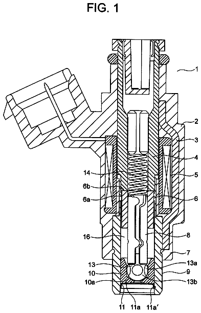
Each fuel injector 21 injects the fuel sent from a fuel pump (disposed out of the range of the drawings) into the cylinder 2 . In this embodiment, the fuel injector 21 is an outward opening valve type. The structure of the fuel injector 21 is briefly described by using FIG. 5 which is a schematic cross-sectional view of the fuel injector 21 . As illustrated in FIG. 5 , the fuel injector 21 has a fuel tube 21 c formed with a nozzle port 21 b at a tip part thereof, and an outward opening type valve 21 a disposed inside of the fuel tube 21 c for opening and closing the nozzle port 21 b. The outward opening type valve 21 a is connected with a piezo element 21 d for deforming according to applied voltage, and positionally shifts between an opening position and a closing position according to the deformation of the piezo element 21 d. At the opening position, the outward opening type valve 21 a protrudes from the nozzle port 21 b to the tip side to open the nozzle port 21 b. At the closing position, the outward opening type valve 21 a closes the nozzle port 21 b.
In this embodiment, the premixed charge compression self-ignition combustion is performed, in which the fuel and air are premixed to form a mixture gas and the mixture gas is compressed to self-ignite near the TDC on compression stroke (CTDC) throughout all operating ranges of the engine body. Accordingly, in the example of FIG. 4 , ignition plugs for igniting the gas inside the cylinders 2 are not provided to the engine body 1 ; however, in a case where an additional ignition power is required for suitable combustion of the mixture gas in a cold start etc., the ignition plugs may suitably be provided to the engine body 1 .
Control System
(3-1) System Configuration
FIG. 6 is a block diagram illustrating a control system of the engine. As illustrated in FIG. 6 , the engine system of this embodiment is controlled by a Powertrain Control Module (PCM) 100 as a whole. The PCM 100 (controller) is, as is well-known, comprised of a microprocessor including a CPU, a ROM, and a RAM.
The PCM 100 is electrically connected with various sensors for detecting an operating state of the engine.
For example, the cylinder block 3 is provided with a crank angle sensor SN 1 for detecting a rotational angle and speed of a crankshaft, in other words, an engine speed. Further, an airflow sensor SN 2 for detecting an air amount (fresh air amount) to be sucked into the cylinders 2 through the air cleaner 31 is provided in the intake passage 30 , between the air cleaner 31 and the throttle valve 32 . Moreover, an accelerator opening sensor SN 3 for detecting a position of an accelerator pedal (accelerator opening) which is disposed out of the range of the drawings and controlled by a driver of the vehicle is provided to the vehicle.
The PCM 100 controls respective parts of the engine while performing various determinations, operations etc. based on input signals from the various sensors. Specifically, the PCM 100 is electrically connected with the fuel injectors 21 , the water injectors 22 , the throttle valve 32 , the exhaust shutter valve 44 , the EGR valve 52 , the water injection pump 63 , etc., and outputs control signals to these components based on results of the operations, etc.
FIG. 7 is a control map of which a horizontal axis indicates the engine speed and a vertical axis indicates an engine load. In this embodiment, since the premixed charge compression self-ignition combustion is performed throughout all the operating ranges as described above, to achieve suitable premixed charge compression self-ignition combustion in every operation condition, a low engine load range A 1 where the engine load is a predetermined reference load Tq 1 or below, and a high engine load range A 2 (critical water injecting range) where the engine load is higher than the reference load Tq 1 are set as control ranges. Hereinafter, contents of the control in the respective ranges A 1 and A 2 are described.
Here, the PCM 100 includes an engine load determining module for receiving a parameter of the engine load that varies based on the accelerator opening, and determining whether an operating state of the engine body is a first state where the engine load is below a predetermined switch load (described later) or a second state where the engine load is the predetermined switch load or above.
(3-2) Low Engine Load Range
Within the low engine load range A 1 , a requested engine torque is low, and thus, an effective compression ratio may be set small. Therefore, within the low engine load range A 1 , the effective compression ratio is set to a low value so as to reduce a pumping loss and increase energy efficiency. For example, the effective compression ratio is reduced lower than 15:1. Specifically, each intake valve 18 is closed at a comparatively retarded timing on a retarding side of the BDC on intake stroke by the intake variable valve timing mechanism 18 a, and thus, the effective compression ratio is reduced.
Within the low engine load range A 1 , since a heat generation amount of the mixture gas is small and a combustion temperature is comparatively low, an amount of No (so-called Raw No.sub.x) produced by the combustion becomes low. Thus, within this range A 1 , there is no need to purify No.sub.x by the three-way catalyst 41 , and an air-fuel ratio is not required to be a theoretical air-fuel ratio at which the No can be purified by the three-way catalyst. Therefore, within the low engine load range A 1 , the air-fuel ratio of the mixture gas is set to be lean, in other words, an air excess ratio λ>1, so as to improve fuel consumption.
Further within the low engine load range A 1 , in a latter half of the compression stroke (between 90° CA before the CTDC and the CTDC), all the fuel for one combustion cycle is injected into each cylinder 2 at once by the fuel injector 21 . For example, all the fuel is injected into the cylinder 2 near 30° CA before the CTDC.
Here, if an ignition delay time (a period of time from the injection of the fuel into the cylinder 2 to an ignition of the mixture gas) is short, the combustion starts in a state where the injected fuel is not sufficiently mixed with air. Thus, in this case, pressure inside the cylinder 2 (in-cylinder pressure) sharply increases, which causes issues of worsening combustion noise and producing more smoke.
Therefore, within the low engine load range A 1 , the EGR gas, which is a substance other than fuel and air, in other words, an inactive substance, is recirculated into the cylinder 2 so as to secure a suitable length of ignition delay time and start the combustion after the fuel is sufficiently mixed with air. Specifically, by introducing the EGR gas, which is the inactive substance, into the cylinder 2 , a ratio of an amount of the fuel and air to a total gas amount inside the cylinder 2 becomes small, and an increase in the gas temperature inside the cylinder 2 is suppressed. Therefore, a reaction speed of the fuel and air is reduced and the ignition delay time can be extended.
Specifically, within the low engine load range A 1 , the EGR valve 52 is opened, and a portion of the exhaust gas inside the exhaust passage 40 is recirculated to the intake passage 30 , as the EGR gas. Moreover, within an engine operating range where the engine load is extremely low and pressure inside the exhaust passage 40 , in other words, pressure on the upstream side of the EGR passage 51 , is low, the opening of the exhaust shutter valve 44 is narrowed and the EGR gas recirculation is stimulated.
In this embodiment, within the low engine load range A 1 , the EGR gas is recirculated so that a G/F which is a ratio of a total gas weight inside the cylinder 2 to the fuel amount becomes 35 or above.
Moreover, since the ignition delay time easily becomes short as the engine load increases and the injected fuel amount increases, an EGR ratio (a ratio of a weight of the EGR gas to a weight of all substances inside the cylinder 2 ) is increased as the engine load becomes higher, so as to suitably secure the ignition delay time in every engine load. A solid line of FIG. 8 indicates an EGR ratio with respect to the engine load at a predetermined engine speed. As indicated by the solid line of FIG. 8 , in this embodiment, the weight of EGR gas is increased in proportion to the engine load within the low engine load range A 1 .
In FIG. 8 , the dashed line indicates a water injection ratio which is a ratio of a weight of the supercritical water injected into the cylinder 2 from the water injector 22 , to the weight of all substances inside the cylinder 2 . As indicated by the dashed line of FIG. 8 , within the low engine load range A 1 , the injection of the supercritical water into the cylinder 2 by the water injector 22 is stopped. Accordingly, the drive of the water injection pump 63 is stopped.
As described above, within the low engine load range A 1 , the injection amount of the supercritical water into the cylinder 2 is set to zero, which is smaller than the EGR gas amount introduced into the cylinder 2 .
Here, in the above-described definition that the ignition delay time is the time period from the fuel injection to the ignition timing of the mixture gas, the ignition timing is a timing at which a cool-flame reaction of the mixture gas is completed and a hot-flame reaction starts, for which a specific description is given with reference to FIG. 9 .
FIG. 9 is a chart schematically illustrating one example of an injection pulse and a heat release rate when the premixed charge compression self-ignition combustion is performed. As illustrated in FIG. 9 , in the premixed charge compression self-ignition combustion, the fuel is injected at a timing t 1 (injection Q), then the mixture gas starts releasing heat (oxidation reaction) at a timing t 2 at which the temperature and pressure reach predetermined values, and accordingly, the heat release rate gradually increases or first gradually increases and then drops. Then, at a timing t 3 , the heat release rate sharply increases.
Here, low-temperature heat release which is the reaction occurring between the timings t 2 and t 3 and causes a slight heat generation to the extent that the cooling loss, etc. do not occur, is referred to as the cool-flame reaction. Main combustion which occurs after the cool-flame reaction is referred to as the hot-flame reaction. Further, the timing at which the hot-flame reaction starts (the timing at which the heat release rate sharply rises, corresponding to the timing t 3 in FIG. 9 ) is referred to as the ignition timing. A period of time from the fuel injection timing (the timing t 1 in FIG. 9 ) to the ignition timing defined as described above is referred to as the ignition delay time. Note that, in FIG. 9 , although the horizontal axis indicates the crank angle, the ignition delay time is a parameter defined by time, not the crank angle. Moreover, the hot-flame reaction is known to occur when the temperature of the mixture gas becomes about 1,500 K or above. Therefore, a timing at which the temperature of the mixture gas reaches or exceeds 1,500 K may be the ignition timing and a period of time to this timing may be the ignition delay time.
(3-3) High Engine Load Range
Within the high engine load range A 2 , the effective compression ratio is set larger than that within the low engine load range A 1 to secure sufficient engine torque. In this embodiment, the effective compression ratio is set to be 15:1 or above within the high engine load range A 2 . Specifically, the close timing of each intake valve 18 is advanced more than that within the low engine load range A 1 by the intake variable valve timing mechanism 18 a, and thus, the effective compression ratio is set larger than that within the low engine load range A 1 .
Within the high engine load range A 2 , the air-fuel ratio is set to be the theoretical air-fuel ratio so that the No.sub.x can be purified by the three-way catalyst. In other words, the air excess ratio λ is 1.
Within the high engine load range A 2 , the engine load is high and the amount of fuel injected into the cylinder 2 is large. Thus, if such a large amount of fuel is injected into the cylinder 2 at once, the combustion may start in a state where the fuel is not sufficiently mixed with air. Therefore, within the high engine load range A 2 , as illustrated in FIG. 10 , the fuel is divided into a plurality of injections into the cylinder 2 . FIG. 10 illustrates one example of an injection pattern within the high engine load range A 2 . As illustrated in FIG. 10 , within the high engine load range A 2 , a first injection Q 1 in which a comparatively large amount of fuel is injected in an early half of the compression stroke (between the BDC on the intake stroke and 90° CA before the CTDC) is performed, a second injection Q 2 in which a portion of the rest of the fuel is injected in the latter half of the compression stroke is performed, and then a third injection Q 3 in which the rest of the fuel is injected at a timing slightly on the advancing side of the CTDC but on the retarding side of the second injection Q 2 is performed.
The description continues in the full USPTO document.
About 7,038 words. The USPTO PDF has it with every drawing.
Fees are due 3.5, 7.5 and 11.5 years after grant. This patent expired on January 9, 2026, so the fee marked "not paid" was the one that went unpaid.
CONTROL APPARATUS OF PREMIXED CHARGE COMPRESSION IGNITION ENGINE
Filed Jul 2016 · published Jan 2017Control apparatus of premixed charge compression ignition engine
Filed Jul 2016 · granted Jan 2018Earlier publications, parents and continuations. None of them can still be enforced, or this patent would not be listed.
Prior art cited by the examiner or applicant. Useful when you check your own idea for novelty.
Everything on this page comes from the documents linked above.