Cross-reference to related application
The present application claims priority to Japanese Patent Application No. 2015-074273 filed on Mar. 31, 2015, which is incorporated herein by reference in its entirety.
Technical field
Embodiments of the present invention relate to an exhaust purification system of an internal combustion engine.
Background art
Known in the art is an exhaust purification system providing air-fuel ratio sensors at an upstream side in a direction of flow of exhaust and at a downstream side in a direction of flow of exhaust from an exhaust purification catalyst provided in an exhaust passage of an internal combustion engine. In such an internal combustion engine, the output of the upstream side air-fuel ratio sensor is used as the basis for feedback control so that the air-fuel ratio of the exhaust gas flowing into the exhaust purification catalyst becomes a target air-fuel ratio. In addition, the target air-fuel ratio is alternately set to an air-fuel ratio richer than a stoichiometric air-fuel ratio (below, simply referred to as the “rich air-fuel ratio”) and an air-fuel ratio leaner than the stoichiometric air-fuel ratio (below, simply referred to as the “lean air-fuel ratio”) (for example, International Patent Publication No. 2014/118892A).
In particular, in the internal combustion engine which is described in International Patent Publication No. 2014/118892A, when an air-fuel ratio corresponding to an output of the downstream side air-fuel ratio sensor (below, also referred to as the “output air-fuel ratio”) becomes a rich judged air-fuel ratio richer than the stoichiometric air-fuel ratio or becomes a smaller ratio, the target air-fuel ratio is switched to the lean air-fuel ratio while when an oxygen storage amount of the exhaust purification catalyst becomes a predetermined switching reference storage amount smaller than the maximum storable oxygen amount or becomes a larger amount, the target air-fuel ratio is switched to the rich air-fuel ratio. According to International Patent Publication No. 2014/118892A, due to this, it is considered possible to suppress the outflow of NO.sub.x from the exhaust purification catalyst. SUMMARY Technical Problem
In this regard, if an element forming part of an air-fuel ratio sensor cracks, when the air-fuel ratio of the exhaust gas around the air-fuel ratio sensor is the lean air-fuel ratio, the output air-fuel ratio of the air-fuel ratio sensor becomes substantially equal to the actual air-fuel ratio of the exhaust gas. In this regard, when the air-fuel ratio of the exhaust gas around the air-fuel ratio sensor is the rich air-fuel ratio, the output air-fuel ratio of the air-fuel ratio sensor sometimes becomes an air-fuel ratio different from the actual air-fuel ratio of the exhaust gas, in particular a lean air-fuel ratio. Therefore, for example, regarding the downstream side air-fuel ratio sensor, when the air-fuel ratio of the exhaust gas flowing out from the exhaust purification catalyst becomes the rich air-fuel ratio, if the output air-fuel ratio of the downstream side air-fuel ratio sensor becomes the lean air-fuel ratio, it can be judged that the downstream side air-fuel ratio sensor suffers from the abnormality of a cracked element.
On the other hand, the output air-fuel ratio of the upstream side air-fuel ratio sensor sometimes deviates from the average air-fuel ratio of the exhaust gas circulating around the upstream side air-fuel ratio sensor depending on the engine operating state etc. When the extent of deviation in the output air-fuel ratio of the upstream side air-fuel ratio sensor is large, regardless of the air-fuel ratio of the exhaust gas circulating around the upstream side air-fuel ratio sensor being the lean air-fuel ratio, the output air-fuel ratio of the upstream side air-fuel ratio sensor will sometimes become the rich air-fuel ratio.
If in this way the output air-fuel ratio of the upstream side air-fuel ratio sensor deviates, even if the actual air-fuel ratio of the exhaust gas flowing into the exhaust purification catalyst is the lean air-fuel ratio, sometimes the output air-fuel ratio of the upstream side air-fuel ratio sensor will become the rich air-fuel ratio. In this case, if considering the output air-fuel ratio of the upstream side air-fuel ratio sensor, the air-fuel ratio of the exhaust gas flowing out from the exhaust purification catalyst is estimated as being the stoichiometric air-fuel ratio or the rich air-fuel ratio. Therefore, in this case, the output air-fuel ratio of the downstream side air-fuel ratio sensor sometimes becomes the lean air-fuel ratio in the state where the air-fuel ratio of the exhaust gas around the downstream side air-fuel ratio sensor is estimated to be the rich air-fuel ratio. Therefore, if diagnosing the abnormality of a cracked element by the above-mentioned technique, in such a case, the downstream side air-fuel ratio sensor ends up being mistakenly judged to suffer from the abnormality of a cracked element.
Therefore, in consideration of the above issues, an object of embodiments of the present invention is to provide an exhaust purification system of an internal combustion engine which enables an abnormality of a cracked element to be accurately diagnosed when this abnormality occurs at a downstream side air-fuel ratio sensor. Solution to Problem
In order to solve the above problem, in a first embodiment, there is provided an exhaust purification system of an internal combustion engine, comprising an exhaust purification catalyst provided at an exhaust passage of the internal combustion engine, a downstream side air-fuel ratio sensor provided in the exhaust passage at a downstream side in the direction of flow of exhaust from the exhaust purification catalyst, and a control device controlling the air-fuel ratio of the exhaust gas flowing into the exhaust purification catalyst and diagnosing abnormality of the downstream side air-fuel ratio sensor. The control device makes the air-fuel ratio of the exhaust gas flowing into the exhaust purification catalyst change to an air-fuel ratio at a rich side from the prior air-fuel ratio as air-fuel ratio rich increasing control when the air-fuel ratio of the exhaust gas flowing into the exhaust purification catalyst is made a rich air-fuel ratio richer than the stoichiometric air-fuel ratio and the output air-fuel ratio of the downstream side air-fuel ratio sensor is maintained at a lean judged air-fuel ratio leaner than the stoichiometric air-fuel ratio or more. The control device judges that the downstream side air-fuel ratio sensor suffers from an abnormality, when, due to the air-fuel ratio rich increasing control, the air-fuel ratio of the exhaust gas flowing into the exhaust purification catalyst is made to change to the rich side air-fuel ratio and the output air-fuel ratio of the downstream side air-fuel ratio sensor changes to the lean side.
In order to solve the above problem, in a second embodiment, there is provided an exhaust purification system of an internal combustion engine, comprising an exhaust purification catalyst provided at an exhaust passage of the internal combustion engine, a downstream side air-fuel ratio sensor provided in the exhaust passage at a downstream side in the direction of flow of exhaust from the exhaust purification catalyst, and a control device controlling the air-fuel ratio of the exhaust gas flowing into the exhaust purification catalyst and diagnosing abnormality of the downstream side air-fuel ratio sensor. The control device makes the air-fuel ratio of the exhaust gas flowing into the exhaust purification catalyst change to an air-fuel ratio at a rich side from the prior air-fuel ratio as air-fuel ratio rich increasing control when the air-fuel ratio of the exhaust gas flowing into the exhaust purification catalyst is made a rich air-fuel ratio richer than the stoichiometric air-fuel ratio and the output air-fuel ratio of the downstream side air-fuel ratio sensor is maintained at a lean judged air-fuel ratio leaner than the stoichiometric air-fuel ratio or more. The control device makes the air-fuel ratio of the exhaust gas flowing into the exhaust purification catalyst change to an air-fuel ratio richer than the stoichiometric air-fuel ratio and at the lean side from the prior air-fuel ratio as air-fuel ratio lean increasing control when, due to the air-fuel ratio rich increasing control, the air-fuel ratio of the exhaust gas flowing into the exhaust purification catalyst is made to change to an air-fuel ratio at the rich side and the output air-fuel ratio of the downstream side air-fuel ratio sensor changes to the lean side. The control device also judges that the downstream side air-fuel ratio sensor suffers from an abnormality, when, due to the air-fuel ratio lean increasing control, the air-fuel ratio of the exhaust gas flowing into the exhaust purification catalyst is made to change to the lean side air-fuel ratio and the output air-fuel ratio of the downstream side air-fuel ratio sensor changes to the rich side.
In a third embodiment, the control device updates a learning value based on the output of the downstream side air-fuel ratio sensor and controls a parameter relating to the air-fuel ratio so as to make the air-fuel ratio of the exhaust gas flowing into the exhaust purification catalyst change in accordance with the learning value as learning control, and the air-fuel ratio rich increasing control is lean stuck learning control wherein the learning value is updated so as to make the air-fuel ratio of the exhaust gas flowing into the exhaust purification catalyst change to an air-fuel ratio at the rich side from the prior air-fuel ratio in the first or second embodiments.
In a forth embodiment, the control device updates the learning value based on the output of the downstream side air-fuel ratio sensor and controls a parameter relating to the air-fuel ratio so as to make the air-fuel ratio of the exhaust gas flowing into the exhaust purification catalyst change in accordance with the learning value as learning control. The air-fuel ratio rich increasing control is lean stuck learning control wherein the learning value is updated so as to make the air-fuel ratio of the exhaust gas flowing into the exhaust purification catalyst change to an air-fuel ratio at the rich side from the prior air-fuel ratio, and the air-fuel ratio lean increasing control is learning value return control wherein the learning value is updated so as to make the air-fuel ratio of the exhaust gas flowing into the exhaust purification catalyst change to an air-fuel ratio richer than the stoichiometric air-fuel ratio and at the lean side from the prior air-fuel ratio up in the second invention.
In a fifth invention, the control device returns the learning value updated by the lean stuck learning control to the value before the updating when it is judged that the downstream side air-fuel ratio sensor suffers from an abnormality in the third or fourth embodiment.
In a sixth embodiment, the control device controls the air-fuel ratio of the exhaust gas flowing into the exhaust purification catalyst so that the air-fuel ratio of the exhaust gas flowing into the exhaust purification catalyst changes to the rich side in proportion to a rich side absolute value of the learning value with respect to the air-fuel ratio of the exhaust gas flowing into the exhaust purification catalyst when the learning value is zero. The learning value is set so that the rich side absolute value becomes an absolute value of a predetermined rich side guard value or less, and the control device reduces the absolute value of the rich side guard value as guard value restriction control when the downstream side air-fuel ratio sensor suffers from an abnormality in any one of the third to fifth embodiments.
In a seventh embodiment, the control device periodically makes the rich side absolute value of the learning value increase beyond the absolute value of the rich side guard value as abnormal confirmation control so that even if, due to the guard value restriction control, the absolute value of the rich side guard value is reduced, the air-fuel ratio of the exhaust gas flowing into the exhaust purification catalyst changes to the rich side beyond the air-fuel ratio corresponding to the rich side guard value with the reduced absolute value in the sixth embodiment.
In an eighth embodiment, the control device performs feedback control so that the air-fuel ratio of the exhaust gas flowing into the exhaust purification catalyst becomes the target air-fuel ratio, and alternately switches a target air-fuel ratio between the rich air-fuel ratio and lean air-fuel ratio. The target air-fuel ratio being switched from the rich air-fuel ratio to the lean air-fuel ratio when the output air-fuel ratio of the downstream side air-fuel ratio sensor becomes a predetermined rich judged air-fuel ratio richer than the stoichiometric air-fuel ratio or becomes a smaller ratio. The control device, in the learning control, based on a cumulative oxygen excess amount being the cumulative value of the amount of oxygen which becomes an excess when trying to make the air-fuel ratio of the exhaust gas flowing into the exhaust purification catalyst the stoichiometric air-fuel ratio in an oxygen increasing period from when the target air-fuel ratio is switched to the lean air-fuel ratio when the target air-fuel ratio is switched again to the rich air-fuel ratio, and a cumulative oxygen deficiency amount being the cumulative value of the amount of oxygen which becomes deficient when trying to make the air-fuel ratio of the exhaust gas flowing into the exhaust purification catalyst the stoichiometric air-fuel ratio in the oxygen decreasing period from when the target air-fuel ratio is switched to the rich air-fuel ratio when the target air-fuel ratio is switched again to the lean air-fuel ratio, updates the learning value so that the difference between these cumulative oxygen excess amount and cumulative oxygen deficiency amount becomes smaller, and the control device reduces the ratio of the amount of change of the learning value with respect to the difference of the cumulative oxygen excess amount and the cumulative oxygen deficiency amount in the case cumulative oxygen excess amount is smaller than the cumulative oxygen deficiency amount, when it is judged that the downstream side air-fuel ratio sensor suffers from an abnormality, compared to when it is not judged that the downstream side air-fuel ratio sensor suffers from an abnormality in any one of the third to fifth embodiments.
In a ninth embodiment, the control device performs feedback control so that the air-fuel ratio of the exhaust gas flowing into the exhaust purification catalyst becomes a target air-fuel ratio and switches the target air-fuel ratio from the rich air-fuel ratio to the lean air-fuel ratio when the output air-fuel ratio of the downstream side air-fuel ratio sensor becomes a predetermined rich judged air-fuel ratio richer than the stoichiometric air-fuel ratio or becomes a small ratio, and switches the target air-fuel ratio from the lean air-fuel ratio to the rich air-fuel ratio when the oxygen storage amount of the exhaust purification catalyst becomes at least a predetermined switching reference storage amount smaller than a maximum storable amount in any one of the first to eighth embodiments.
In a tenth embodiment, there is provided an exhaust purification method for an internal combustion engine, where an exhaust purification catalyst is provided at an exhaust passage of the internal combustion engine, a downstream side air-fuel ratio sensor is provided in the exhaust passage at a downstream side in the direction of flow of exhaust from the exhaust purification catalyst, and a control device controls the air-fuel ratio of the exhaust gas flowing into the exhaust purification catalyst and diagnosing abnormality of the downstream side air-fuel ratio sensor. The control device: either a) makes the air-fuel ratio of the exhaust gas flowing into the exhaust purification catalyst change to an air-fuel ratio at a rich side from the prior air-fuel ratio as air-fuel ratio rich increasing control when the air-fuel ratio of the exhaust gas flowing into the exhaust purification catalyst is made a rich air-fuel ratio richer than the stoichiometric air-fuel ratio and the output air-fuel ratio of the downstream side air-fuel ratio sensor is maintained at a lean judged air-fuel ratio leaner than the stoichiometric air-fuel ratio or more, and b) judges that the downstream side air-fuel ratio sensor suffers from an abnormality, when, due to the air-fuel ratio rich increasing control, the air-fuel ratio of the exhaust gas flowing into the exhaust purification catalyst is made to change to the rich side air-fuel ratio and the output air-fuel ratio of the downstream side air-fuel ratio sensor changes to the lean side; or a) makes the air-fuel ratio of the exhaust gas flowing into the exhaust purification catalyst change to an air-fuel ratio at a rich side from the prior air-fuel ratio as air-fuel ratio rich increasing control when the air-fuel ratio of the exhaust gas flowing into the exhaust purification catalyst is made a rich air-fuel ratio richer than the stoichiometric air-fuel ratio and the output air-fuel ratio of the downstream side air-fuel ratio sensor is maintained at a lean judged air-fuel ratio leaner than the stoichiometric air-fuel ratio or more, b) makes the air-fuel ratio of the exhaust gas flowing into the exhaust purification catalyst change to an air-fuel ratio richer than the stoichiometric air-fuel ratio and at the lean side from the prior air-fuel ratio as air-fuel ratio lean increasing control when, due to the air-fuel ratio rich increasing control, the air-fuel ratio of the exhaust gas flowing into the exhaust purification catalyst is made to change to an air-fuel ratio at the rich side and the output air-fuel ratio of the downstream side air-fuel ratio sensor changes to the lean side, and c) judges that the downstream side air-fuel ratio sensor suffers from an abnormality, when, due to the air-fuel ratio lean increasing control, the air-fuel ratio of the exhaust gas flowing into the exhaust purification catalyst is made to change to the lean side air-fuel ratio and the output air-fuel ratio of the downstream side air-fuel ratio sensor changes to the rich side. Potential Advantageous Effects of Embodiments of the Present Invention
According to embodiments of the present invention, there is provided an exhaust purification system of an internal combustion engine able to accurately diagnose an abnormality of a cracked element when a downstream side air-fuel ratio sensor suffers from such an abnormality.
Brief description of drawings
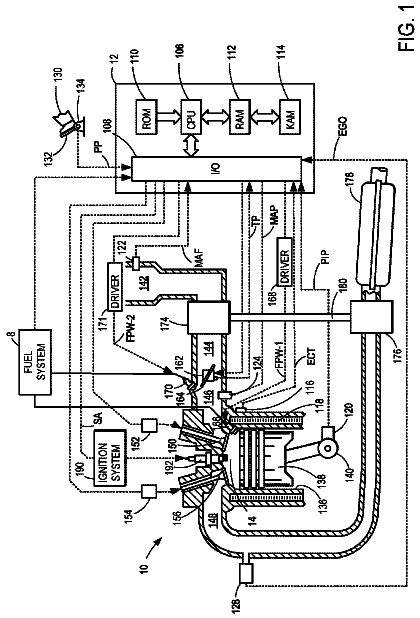
FIG. 1 is a view schematically showing an internal combustion engine in which the abnormality diagnosis system of embodiments of the present invention is used.
FIG. 2 is a schematic cross-sectional view of an air-fuel ratio sensor.
FIG. 3 is a view showing a relationship of an applied voltage V and output current I at different exhaust air-fuel ratios A/F.
FIG. 4 is a view showing a relationship of an air-fuel ratio and output current I when making the applied voltage V constant.
FIG. 5 is a time chart showing a change of oxygen storage amount etc. of an upstream side exhaust purification catalyst at the time of normal operation of an internal combustion engine.
FIG. 6 is a time chart, similar to FIG. 5 , showing a change of oxygen storage amount etc. of an upstream side exhaust purification catalyst.
FIG. 7 is a time chart of a control center air-fuel ratio etc.
FIG. 8 is a time chart of an air-fuel ratio correction amount etc. when a large deviation occurs in an output value of an upstream side air-fuel ratio sensor.
FIG. 9 is a time chart of an air-fuel ratio correction amount etc. when a large deviation occurs in an output value of an upstream side air-fuel ratio sensor.
FIG. 10 is a time chart of an air-fuel ratio correction amount etc. when performing stoichiometric air-fuel ratio stuck learning.
FIG. 11 is a time chart of an air-fuel ratio correction amount etc. when performing lean stuck learning etc.
FIG. 12 is a schematic cross-sectional view of an air-fuel ratio sensor suffering from a cracked element.
FIG. 13 is a view showing a relationship of an exhaust air-fuel ratio and the voltage V and an output air-fuel ratio of the air-fuel ratio sensor similar to FIG. 3 when making the applied voltage constant.
FIG. 14 is a time chart of a control center air-fuel ratio etc.
FIG. 15 is a time chart of a control center air-fuel ratio etc.
FIG. 16 is a functional block diagram of a control device.
FIG. 17 is a flow chart showing a control routine of processing for calculating an air-fuel ratio correction amount.
FIG. 18 is a flow chart showing a control routine of normal learning control.
FIG. 19 is a flow chart showing a control routine of stuck learning control.
FIG. 20 is a flow chart showing a control routine of control for diagnosing abnormality and setting a learning value.
FIG. 21 is a time chart of a control center air-fuel ratio etc.
FIG. 22 is a time chart of a control center air-fuel ratio etc.
FIG. 23 is a flow chart showing a control routine of learning value correction control wherein a learning value is corrected based on a guard value.
FIG. 24 is a flow chart showing a control routine of control for confirmation of an abnormality.
FIG. 25 is a time chart of a control center air-fuel ratio etc.
FIG. 26 is a flow chart showing a control routine of control for diagnosing an abnormality and setting a learning value.
Description of embodiments
Below, referring to the drawings, embodiments of the present invention will be explained in detail. Note that, in the following explanation, similar component elements are assigned the same reference numerals.
<Explanation of Internal Combustion Engine as a Whole>
FIG. 1 is a view which schematically shows an internal combustion engine in which an exhaust purification system according to a first embodiment of the present invention is used. Referring to FIG. 1, 1 indicates an engine body, 2 a cylinder block, 3 a piston which reciprocates inside the cylinder block 2 , 4 a cylinder head which is fastened to the cylinder block 2 , 5 a combustion chamber which is formed between the piston 3 and the cylinder head 4 , 6 an intake valve, 7 an intake port, 8 an exhaust valve, and 9 an exhaust port. The intake valve 6 opens and closes the intake port 7 , while the exhaust valve 8 opens and closes the exhaust port 9 .
As shown in FIG. 1 , a spark plug 10 is arranged at a center part of an inside wall surface of the cylinder head 4 , while a fuel injector 11 is arranged at a side part of the inner wall surface of the cylinder head 4 . The spark plug 10 is configured to generate a spark in accordance with an ignition signal. Further, the fuel injector 11 injects a predetermined amount of fuel into the combustion chamber 5 in accordance with an injection signal. Note that, the fuel injector 11 may also be arranged so as to inject fuel into the intake port 7 . Further, in the present embodiment, gasoline with a stoichiometric air-fuel ratio of 14.6, is used as the fuel. However, the internal combustion engine using the exhaust purification system of the present invention may also use fuel other than gasoline, or mixed fuel with gasoline.
The intake port 7 of each cylinder is connected to a surge tank 14 through a corresponding intake runner 13 , while the surge tank 14 is connected to an air cleaner 16 through an intake pipe 15 . The intake port 7 , intake runner 13 , surge tank 14 , and intake pipe 15 form an intake passage. Further, inside the intake pipe 15 , a throttle valve 18 which is driven by a throttle valve drive actuator 17 is arranged. The throttle valve 18 can be operated by the throttle valve drive actuator 17 to thereby change the aperture area of the intake passage.
On the other hand, the exhaust port 9 of each cylinder is connected to an exhaust manifold 19 . The exhaust manifold 19 has a plurality of runners which are connected to the exhaust ports 9 and a header at which these runners are collected. The header of the exhaust manifold 19 is connected to an upstream side casing 21 which houses an upstream side exhaust purification catalyst 20 . The upstream side casing 21 is connected through an exhaust pipe 22 to a downstream side casing 23 which houses a downstream side exhaust purification catalyst 24 . The exhaust port 9 , exhaust manifold 19 , upstream side casing 21 , exhaust pipe 22 , and downstream side casing 23 form an exhaust passage.
The electronic control unit (ECU) 31 is comprised of a digital computer which is provided with components which are connected together through a bidirectional bus 32 such as a RAM (random access memory) 33 , ROM (read only memory) 34 , CPU (microprocessor) 35 , input port 36 , and output port 37 . In the intake pipe 15 , an air flow meter 39 is arranged for detecting the flow rate of air which flows through the intake pipe 15 . The output of this air flow meter 39 is input through a corresponding AD converter 38 to the input port 36 . Further, at the header of the exhaust manifold 19 , an upstream side air-fuel ratio sensor 40 is arranged which detects the air-fuel ratio of the exhaust gas which flows through the inside of the exhaust manifold 19 (that is, the exhaust gas which flows into the upstream side exhaust purification catalyst 20 ). In addition, in the exhaust pipe 22 , a downstream side air-fuel ratio sensor 41 is arranged which detects the air-fuel ratio of the exhaust gas which flows through the inside of the exhaust pipe 22 (that is, the exhaust gas which flows out from the upstream side exhaust purification catalyst 20 and flows into the downstream side exhaust purification catalyst 24 ). The outputs of these air-fuel ratio sensors 40 and 41 are also input through the corresponding AD converters 38 to the input port 36 . Note that, the configurations of these air-fuel ratio sensors 40 and 41 will be explained later.
Further, an accelerator pedal 42 has a load sensor 43 connected to it which generates an output voltage which is proportional to the amount of depression of the accelerator pedal 42 . The output voltage of the load sensor 43 is input to the input port 36 through a corresponding AD converter 38 . The crank angle sensor 44 generates an output pulse every time, for example, a crankshaft rotates by 15 degrees. This output pulse is input to the input port 36 . The CPU 35 calculates the engine speed from the output pulse of this crank angle sensor 44 . On the other hand, the output port 37 is connected through corresponding drive circuits 45 to the spark plugs 10 , fuel injectors 11 , and throttle valve drive actuator 17 . Note that, ECU 31 acts as a control device carrying out various types of control.
The upstream side exhaust purification catalyst 20 and the downstream side exhaust purification catalyst 24 are three-way catalysts which have an oxygen storage ability. Specifically, the exhaust purification catalysts 20 and 24 are three-way catalysts which comprises a carrier made of ceramic on which a precious metal (for example, platinum Pt) having a catalyst effect and a substance having an oxygen storage ability (for example, ceria CeO.sub.2) are carried. A three-way catalyst has the function of simultaneously purifying unburned HC, CO and NO.sub.x when the air-fuel ratio of the exhaust gas flowing into the three-way catalyst is maintained at the stoichiometric air-fuel ratio. In addition, when the exhaust purification catalysts 20 and 24 store a certain extent of oxygen, the unburned HC and CO and NO.sub.x are simultaneously purified even if the air-fuel ratio of the exhaust gas flowing into the exhaust purification catalysts 20 and 24 somewhat deviates from the stoichiometric air-fuel ratio to the rich side or lean side.
Accordingly, if the exhaust purification catalysts 20 and 24 have an oxygen storage ability, that is, if the oxygen storage amount of the exhaust purification catalysts 20 and 24 is less than the maximum storage oxygen amount, when the air-fuel ratio of the exhaust gas flowing into the exhaust purification catalysts 20 , 24 becomes somewhat leaner than the stoichiometric air-fuel ratio, the excess oxygen contained in the exhaust gas is stored in the exhaust purification catalysts 20 , 24 . Therefore, the surfaces of the exhaust purification catalysts 20 and 24 are maintained at the stoichiometric air-fuel ratio. As a result, on the surfaces of the exhaust purification catalysts 20 and 24 , the unburned HC, CO and NO.sub.x are simultaneously purified. At this time, the air-fuel ratio of the exhaust gas flowing out from the exhaust purification catalysts 20 and 24 becomes the stoichiometric air-fuel ratio.
On the other hand, if exhaust purification catalysts 20 and 24 can release oxygen, that is, the oxygen storage amount of the exhaust purification catalysts 20 and 24 is more than zero, when the air-fuel ratio of the exhaust gas flowing into the exhaust purification catalysts 20 , 24 becomes somewhat richer than the stoichiometric air-fuel ratio, the oxygen which is insufficient for reducing the unburned HC and CO contained in the exhaust gas, is released from the exhaust purification catalysts 20 and 24 . Therefore, the surfaces of the exhaust purification catalysts 20 and 24 are maintained at the stoichiometric air-fuel ratio. As a result, on the surfaces of the exhaust purification catalysts 20 and 24 , the unburned HC, CO and NO.sub.x are simultaneously purified. At this time, the air-fuel ratio of the exhaust gas flowing out from the exhaust purification catalysts 20 and 24 becomes the stoichiometric air-fuel ratio.
In this way, when the exhaust purification catalysts 20 and 24 store a certain extent of oxygen, even if the air-fuel ratio of the exhaust gas flowing into the exhaust purification catalysts 20 and 24 deviates somewhat from the stoichiometric air-fuel ratio to the rich side or lean side, the unburned HC, CO and NO.sub.x are simultaneously purified and the air-fuel ratio of the exhaust gas flowing out from the exhaust purification catalysts 20 and 24 becomes the stoichiometric air-fuel ratio.
<Explanation of Air-Fuel Ratio Sensor>
In the present embodiment, as the air-fuel ratio sensors 40 and 41 , cup type limit current type air-fuel ratio sensors are used. FIG. 2 will be used to simply explain the structures of the air-fuel ratio sensors 40 and 41 . Each of the air-fuel ratio sensors 40 and 41 is provided with a solid electrolyte layer 51 , an exhaust side electrode 52 which is arranged on one side surface of the same, an atmosphere side electrode 53 which is arranged on the other side surface, a diffusion regulation layer 54 which regulates the diffusion of the flowing exhaust gas, a reference gas chamber 55 , and a heater part 56 which heats the air-fuel ratio sensor 40 or 41 , in particular the solid electrolyte layer 51 .
In particular, in each of the cup type air-fuel ratio sensors 40 and 41 of the present embodiment, the solid electrolyte layer 51 is formed into a cylindrical shape with one closed end. Inside of the reference gas chamber 55 which is defined inside of the solid electrolyte layer 51 , atmospheric gas (air) is introduced and the heater part 56 is arranged. On the inside surface of the solid electrolyte layer 51 , an atmosphere side electrode 53 is arranged. On the outside surface of the solid electrolyte layer 51 , an exhaust side electrode 52 is arranged. On the outside surfaces of the solid electrolyte layer 51 and the exhaust side electrode 52 , a diffusion regulation layer 54 is arranged to cover the same. Note that, at the outside of the diffusion regulation layer 54 , a protective layer (not shown) may be provided for preventing a liquid etc. from depositing on the surface of the diffusion regulation layer 54 .
The solid electrolyte layer 51 is formed by a sintered body of ZrO.sub.2 (zirconia), HfO.sub.2, ThO.sub.2, Bi.sub.2O.sub.3, or other oxygen ion conducting oxide in which CaO, MgO, Y.sub.2O.sub.3, Yb.sub.2O.sub.3, etc. is blended as a stabilizer. Further, the diffusion regulation layer 54 is formed by a porous sintered body of alumina, magnesia, silica, spinel, mullite, or another heat resistant inorganic substance. Furthermore, the exhaust side electrode 52 and atmosphere side electrode 53 are formed by platinum or other precious metal with a high catalytic activity.
Further, between the exhaust side electrode 52 and the atmosphere side electrode 53 , sensor voltage V is supplied by the voltage control device 60 which is mounted on the ECU 31 . In addition, the ECU 31 is provided with a current detection portion 61 which detects the current I which flows between these electrodes 52 and 53 through the solid electrolyte layer 51 when the sensor voltage V is applied. The current which is detected by this current detection portion 61 is the output current I of the air-fuel ratio sensors 40 and 41 .
The thus configured air-fuel ratio sensors 40 and 41 have the voltage-current (V-I) characteristic such as shown in FIG. 3 . As will be understood from FIG. 3 , the output current I of the air-fuel ratio sensors 40 and 41 becomes larger the higher (leaner) the air-fuel ratio of the exhaust gas, i.e., the exhaust air-fuel ratio A/F. Further, at the line V-I of each exhaust air-fuel ratio A/F, there is a region parallel to the sensor voltage V axis, that is, a region where the output current I does not change much at all even if the sensor voltage V changes. This voltage region is called the “limit current region”. The current at this time is called the “limit current”. In FIG. 3 , the limit current region and limit current when the exhaust air-fuel ratio is 18 are shown by W.sub.18 and I.sub.18.
FIG. 4 is a view which shows the relationship between the exhaust air-fuel ratio and the output current I when making the supplied voltage V constant at about 0.45V ( FIG. 3 ). As will be understood from FIG. 4 , in the air-fuel ratio sensors 40 and 41 , the output current changes linearly (proportionally) changes with respect to the exhaust air-fuel ratio so that the higher (i.e., the leaner) the exhaust air-fuel ratio, the greater the output current I from the air-fuel ratio sensors 40 and 41 . In addition, the air-fuel ratio sensors 40 and 41 are configured so that the output current I becomes zero when the exhaust air-fuel ratio is the stoichiometric air-fuel ratio.
Note that, as the air-fuel ratio sensors 40 and 41 , instead of the limit current type air-fuel ratio sensor having the structure shown in FIG. 2 , it is also possible to use a layered-type limit current type air-fuel ratio sensor.
<Basic Air-Fuel Ratio Control>
Next, the basic air-fuel ratio control in the internal combustion engine of the present embodiment will be summarized. In the air-fuel ratio control in the present embodiment, feedback control is performed based on the output air-fuel ratio of the upstream side air-fuel ratio sensor 40 to control the fuel injection amount from the fuel injector 11 so that the output air-fuel ratio of the upstream side air-fuel ratio sensor 40 becomes the target air-fuel ratio. That is, in the air-fuel ratio control in the present embodiment, feedback control is performed based on the output air-fuel ratio of the upstream side air-fuel ratio sensor 40 so that the air-fuel ratio of the exhaust gas flowing into the upstream side exhaust purification catalyst 20 becomes the target air-fuel ratio. Note that, the “output air-fuel ratio” means the air-fuel ratio which corresponds to the output value of the air-fuel ratio sensor.
Further, in the air-fuel ratio control of the present embodiment, target air-fuel ratio is set based on the output air-fuel ratio of the downstream side air-fuel ratio sensor 41 , etc. Specifically, when the output air-fuel ratio of the downstream side air-fuel ratio sensor 41 becomes a rich air-fuel ratio the target air-fuel ratio is set to a lean set air-fuel ratio. As a result, the air-fuel ratio of exhaust gas flowing into the upstream side exhaust purification catalyst 20 also becomes the lean set air-fuel ratio. In this case, “lean set air-fuel ratio” is a predetermined constant air-fuel ratio which is leaner than the stoichiometric air-fuel ratio (air-fuel ratio serving as center of control) by a certain extent, and, for example, is 14.65 to 20, preferably 14.65 to 18, more preferably 14.65 to 16 or so. Further, the lean set air-fuel ratio can be expressed as an air-fuel ratio acquired by adding a positive air-fuel correction amount to an air-fuel ratio serving as a control center (in the present embodiment, the stoichiometric air-fuel ratio). In addition, in the present embodiment, when the output air-fuel ratio of the downstream side air-fuel ratio sensor 41 becomes a rich judged air-fuel ratio (for example, 14.55), which is slightly richer than the stoichiometric air-fuel ratio, or less, it is judged that the output air-fuel ratio of the downstream side air-fuel ratio sensor 41 has become the rich air-fuel ratio.
If the target air-fuel ratio is changed to the lean set air-fuel ratio, the oxygen excess/deficiency of the exhaust gas which flows into the upstream side exhaust purification catalyst 20 is cumulatively added. The “oxygen excess/deficiency” means an amount of the oxygen which becomes excessive or the oxygen which becomes deficient (excess HC, CO, etc., (below, referred to as unburned gas)) when trying to make the air-fuel ratio of the exhaust gas which flows into the upstream side exhaust purification catalyst 20 the stoichiometric air-fuel ratio. In particular, when the target air-fuel ratio is the lean set air-fuel ratio, the exhaust gas which flows into the upstream side exhaust purification catalyst 20 becomes excessive in oxygen. This excess oxygen is stored in the upstream side exhaust purification catalyst 20 . Therefore, the cumulative value of the oxygen excess/deficiency (below, also referred to as the “cumulative oxygen excess/deficiency”) can be said to express the estimated value of the oxygen storage amount OSA of the upstream side exhaust purification catalyst 20 .
Note that, the oxygen excess/deficiency is calculated based on the output air-fuel ratio of the upstream side air-fuel ratio sensor 40 , and the estimated value of the intake air amount to the inside of the combustion chamber 5 which is calculated based on the output of the air flow meter 39 , etc. or the fuel feed amount of the fuel injector 11 , etc. Specifically, the oxygen excess/deficiency OED is, for example, calculated by the following formula (1): OED=0.23× Qi ×(AFup−AFR)
where 0.23 indicates the concentration of oxygen in the air, Qi indicates the amount of fuel injection, AFup indicates the output air-fuel ratio of the upstream side air-fuel ratio sensor 40 , and AFR indicates an air-fuel ratio serving as control center (in the present embodiment, basically stoichiometric air-fuel ratio).
The description continues in the full USPTO document.
 Lapsed, fee not paid4 drawings