 Lapsed, fee not paid6 drawings
Vehicles & Drones · US 9,863,290 B2
Valve timing adjusting device
A valve timing adjusting device includes a housing, a vane rotor, a sleeve, and a spool.
US 9,863,292 B2 · Assignee: AISIN SEIKI KABUSHIKI KAISHA · Inventors: Ishihara; Hiromitsu
Sheet 1 of 9 from the published document. All sheets in the USPTO PDF
A structure of an air flow control valve includes: valve main body portions respectively provided in intake ports, and controlling the flow of a fluid supplied to combustion chambers of an internal combustion engine; connecting shafts provided integrally with the valve main body portions, and connecting the valve main body portions; a first bearing member formed of a single member having a first bearing hole turnably supporting the connecting shaft at a first end; and a second bearing member provided separately from the first bearing member, and formed of a single member having a second bearing hole turnably supporting the connecting shaft at a second end. The connecting shafts are formed integrally with the valve main body portions in a state where the first and second bearing members are respectively fitted onto the connecting shafts connecting the valve main body portions.
In the related art, the structure of an air flow control valve with a plurality of valve main body portions that are respectively provided in each of a plurality of intake ports, and control the flow of a fluid supplied to a combustion chamber of an internal combustion engine has been known (for example, refer to EP-1388652 (Reference 1)). EP-1388652 (Reference 1) discloses the structure of the valve (the structure of the air flow control valve) for opening and closing each of the intake ports in an intake manifold (intake device) with the plurality of intake ports. In the structure of the valve disclosed in EP-1388652 (Reference 1), the plurality of intake ports are respectively provided with a plurality of flaps (valve main body portions), each of which has a curved shape and is disposed so as to be turnable in the intake port, and a plurality of shafts (turning shafts (connecting shaf
1 of 9 drawing sheets so far from the published document, cropped to the drawing. Every sheet is in the USPTO PDF.
What the patent claimed, word for word. All of it is now free to use.
This application is based on and claims priority under 35 U.S.C. §119 to Japanese Patent Application 2014-012414, filed on Jan. 27, 2014, the entire contents of which are incorporated herein by reference.
This disclosure relates to a structure of an air flow control valve and an intake device, particularly, to a structure of an air flow control valve and an intake device with a plurality of valve main body portions that are respectively provided in each of a plurality of intake ports, and control the flow of a fluid supplied to a combustion chamber of an internal combustion engine.
In the related art, the structure of an air flow control valve with a plurality of valve main body portions that are respectively provided in each of a plurality of intake ports, and control the flow of a fluid supplied to a combustion chamber of an internal combustion engine has been known (for example, refer to EP-1388652 (Reference 1)).
EP-1388652 (Reference 1) discloses the structure of the valve (the structure of the air flow control valve) for opening and closing each of the intake ports in an intake manifold (intake device) with the plurality of intake ports. In the structure of the valve disclosed in EP-1388652 (Reference 1), the plurality of intake ports are respectively provided with a plurality of flaps (valve main body portions), each of which has a curved shape and is disposed so as to be turnable in the intake port, and a plurality of shafts (turning shafts (connecting shafts)), each of which connects the adjacent flaps. Each of the shafts is turnably supported by a bearing structure formed in a wall portion of the intake port. In the configuration of the intake port, an inner circumferential surface (bearing surface) is formed in a bearing portion formed of bearing member pieces which are assembled in such a manner that two pre-split bearing member pieces face each other and the shaft is interposed between the bearing member pieces.
In the structure of the valve (the structure of the air flow control valve) in the intake manifold (intake device) disclosed in EP-1388652 (Reference 1), since the inner circumferential surface (bearing surface) is formed in the bearing portion formed of the bearing member pieces which are assembled in such a manner that the two split bearing member pieces face each other and the shaft is interposed between the bearing member pieces, it is necessary to set a clearance (gap) between an outer surface of the shaft (connecting shaft) and the bearing surface (inner surface) of the bearing portion formed of the bearing member pieces, while taking into consideration an assembly error (a relative positional offset between the bearing member pieces originating from the assembly of the bearing member pieces).
That is, it is necessary to set the clearance (the clearance between the outer surface of the shaft and the bearing surface of the bearing member pieces) to be slightly large so that a given gap is ensured even when the relative positional offset occurs between the bearing member pieces. When the clearance is set to be slightly large, and the shaft turns in a state where an offset (step) is formed between the mating surfaces (the bearing surface) of the bearing member pieces facing each other, the shaft is brought into local contact (partial contact phenomenon) with the bearing surface due to the shape of the step between the bearing surfaces (mating surfaces), and the bearing surface is subjected to wear. When the bearing member pieces are assembled without an occurrence of an assembly error, the gap between the outer surface of the shaft and the bearing surface of the bearing portion increases due to the setting of the clearance (the clearance between the shaft and the bearing portion) to be slightly large, and as a result, backlash of the shaft increases. There is a problem in that when the bearing portion is formed by assembling together a plurality of (two) split bearing member pieces, the bearing surfaces may be subjected to wear due to the stepped shape of the bearing surfaces originating from the assembly error, or the backlash of the shaft (connecting shaft) may increase due to an excessive clearance.
Thus, a need exists for a structure of an air flow control valve and an intake device which are not suspectable to the drawback mentioned above.
A first aspect of this disclosure is directed to a structure of an air flow control valve including: a plurality of valve main body portions that are respectively provided in a plurality of intake ports, and control the flow of a fluid supplied to combustion chambers of an internal combustion engine; connecting shafts that are provided integrally with the plurality of valve main body portions, and connect the plurality of valve main body portions; a first bearing member that is formed of a single member having a first bearing hole which turnably supports the connecting shaft at a first end of the valve main body portion; and a second bearing member that is provided separately from the first bearing member, and is formed of a single member having a second bearing hole which turnably supports the connecting shaft at a second end of the valve main body portion. The connecting shafts are formed integrally with the plurality of valve main body portions in a state where the first bearing member and the second bearing member are respectively fitted onto the connecting shafts that connect the plurality of valve main body portions.
A second aspect of this disclosure is directed to an intake device including: a plurality of valve main body portions that are respectively provided in a plurality of intake ports of an intake device main body, and control the flow of a fluid supplied to combustion chambers of an internal combustion engine; connecting shafts that are provided integrally with the plurality of valve main body portions, and connect the plurality of valve main body portions; a first bearing member that has a first bearing hole which turnably supports the connecting shaft at a first end of the valve main body portion; and a second bearing member that is provided separately from the first bearing member, and has a second bearing hole which turnably supports the connecting shaft at a second end of the valve main body portion. The connecting shafts are formed integrally with the plurality of valve main body portions in a state where the first bearing member and the second bearing member are respectively fitted onto the connecting shaft between the plurality of valve main body portions.
The foregoing and additional features and characteristics of this disclosure will become more apparent from the following detailed description considered with the reference to the accompanying drawings, wherein:
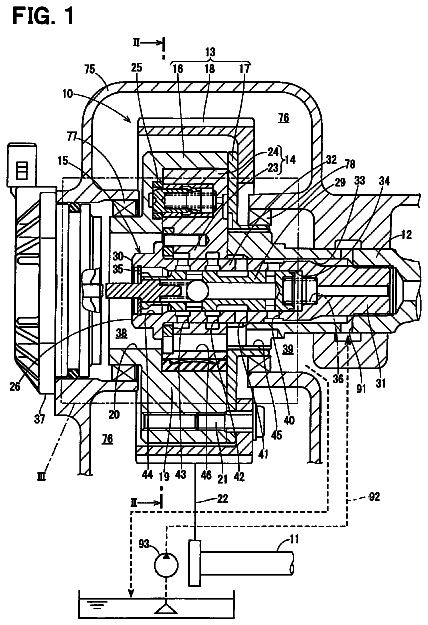
FIG. 1 is a cross-sectional view illustrating a state in which an intake device according to an embodiment of this disclosure is attached to an engine;
FIG. 2 is a cross-sectional view illustrating a state in which the intake device according to the embodiment of this disclosure is attached to the engine;
FIG. 3 is an exploded perspective view illustrating the entire configuration of the intake device according to the embodiment of this disclosure;
FIG. 4 is a side view of the intake device according to the embodiment of this disclosure when seen from a direction in which the intake device is attached to a cylinder head of the engine;
FIG. 5 is a perspective view illustrating the configuration of an assembly component in an intake control valve assembled into the intake device according to the embodiment of this disclosure;
FIG. 6 is a cross-sectional view illustrating a state in which the intake control valve (the assembly component) is assembled into the intake device according to the embodiment of this disclosure;
FIG. 7 is a view illustrating a method of assembling the intake control valve (the assembly component) into the intake device according to the embodiment of this disclosure;
FIG. 8 is a view illustrating a state in which the intake control valve (the assembly component) is assembled into the intake device according to the embodiment of this disclosure;
FIG. 9 is an enlarged view of main portions for illustrating the method of assembling the intake control valve (the assembly component) into the intake device according to the embodiment of this disclosure; and
FIG. 10 is a view illustrating the fitting shape of a bearing member and a bearing member installation portion of a frame member, in the structure of an air flow control valve according to a modification example of this disclosure.
Hereinafter, an embodiment disclosed here will be described with reference to the accompanying drawings.
First, the configuration of an intake device 100 according to the embodiment disclosed here will be described with reference to FIGS. 1 to 9 .
As illustrated in FIG. 1 , the intake device 100 according to the embodiment disclosed here is an intake device mounted on an inline four cylinder engine 200 for a vehicle. As illustrated in FIG. 4 , the intake device 100 includes a surge tank 10 made of resin; a plurality of (four) intake ports 20 that are connected to the outlet ports (the ports positioned on a downstream side in the flow direction of intake air) of the surge tank 10 , and that branch off from the surge tank 10 ; and an intake control valve 30 (refer to FIG. 3 ) that is provided in the vicinity of an outlet port portion of the four intake ports 20 . As illustrated in FIG. 3 , an intake device main body 90 is made by integrally forming the surge tank 10 and the four intake ports 20 via vibration welding. As illustrated in FIG. 1 , with the intake control valve 30 (refer to FIG. 3 ) assembled into the intake device main body 90 , an opening end portion 21 of the intake port 20 is connected to a cylinder head 203 of the engine 200 . The engine 200 is an example of an “internal combustion engine” of the embodiment disclosed here. The intake control valve 30 is an example of an “air flow control valve” of the embodiment disclosed here.
As illustrated in FIG. 1 , the engine 200 has a structure in which the cylinder head 203 is connected to an upper end (an end positioned in a Z1 direction) of a cylinder block 202 that has pistons 201 built therein. The cylinder head 203 includes intake valves 204 for taking air into combustion chambers 203 a ; exhaust valves 205 for discharging combustion gas; ignition plugs 206 for igniting an air/fuel mixture in the combustion chambers 203 a ; and injectors (not illustrated) for supplying fuel to the combustion chambers 203 a . With the function of the engine 200 , during an intake stroke of the piston 201 , the intake valve 204 is opened to take air into the combustion chamber 203 a , and the injector supplies fuel into the combustion chamber 203 a . Thereafter, subsequent to a compression stroke, the air/fuel mixture in the combustion chamber 203 a is burned via the ignition of the air/fuel mixture using the ignition plug 206 , an expanding force originating from the combustion is transmitted from the piston 201 to a crankshaft (not illustrated), and a drive force (power) is produced from the crankshaft.
As illustrated in FIG. 4 , a connecting portion 11 is formed integrally with the surge tank 10 of the intake device 100 , is disposed on an upstream side along the flow of intake air, and is opened to the outside. Here, typically, an air cleaner (not illustrated) and a throttle valve (illustrated by the dotted line) 207 are disposed in an intake air path. The throttle valve 207 is connected to the air cleaner via an air duct (not illustrated) extending from the air cleaner, and an outlet port portion 207 a of the throttle valve 207 is connected to the connecting portion 11 of the surge tank 10 . The intake air reaches the surge tank 10 via the air cleaner and the throttle valve 207 , and flows into the surge tank 10 .
The intake ports 20 made of resin are a molded component that is made by integrally forming a root portion (a portion positioned on the upstream side) of each of the intake ports 20 , and the root portions of the intake ports 20 are respectively connected to opening portions 10 a that are formed from the back surface (the surface positioned on a rear side of the drawing sheet) to the upper surface (the surface positioned on the Z1 direction) of the surge tank 10 . The intake ports 20 branch off from each other, and extend from the root portions connected to the surge tank 10 to the tip ends (the ends positioned on the downstream side) connected to the cylinder head 203 (refer to FIG. 1 ). Openings 22 are formed in the opening end portions 21 of the intake ports 20 connected to the cylinder head 203 , and each of the openings 22 has a predetermined opening area (the cross-sectional area of a flow path). Four opening end portions 21 (the openings 22 ) are disposed in a straight line along an X direction with a predetermined gap held therebetween. As illustrated in FIG. 1 , in the configuration of the intake device main body 90 , the opening end portions 21 are tightened to an attachment surface of the cylinder head 203 while a gasket 50 (refer to FIG. 3 ) fitted to the opening end portions 21 of the intake ports 20 is interposed between the opening end portions 21 and the attachment surface.
As illustrated in FIG. 3 , an actuator unit 60 and a sensor unit 70 are attached to the intake device 100 . The actuator unit 60 drives the intake control valve 30 , and the sensor unit 70 detects the opening of the intake control valve 30 and provides feedback for the drive control of the intake control valve 30 , which will be described later. Specifically, a through-hole 23 is formed in each of the four intake ports 20 that line up in a straight line in the X direction, and the through-hole 23 passes through a portion of an inner wall surface 25 (refer to FIG. 1 ) in a straight line in the X direction and slightly on the upstream side (positioned slightly in a Y2 direction) of the opening end portion 21 . In a state where the intake control valve 30 (to be described later) (an assembly component 35 ) is installed inside the intake ports 20 (in the vicinity of the opening end portions 21 ), the actuator unit 60 is attached to a portion (the portion corresponding to the through-hole 23 ) of a side surface portion 20 a of the intake port 20 at the farthest position in the X1 direction, using screw members 1 , and the sensor unit 70 is attached to a portion (the portion corresponding to the through-hole 23 ) of a side surface portion 20 b of the intake port 20 at the farthest position in an X2 direction, using screw members 2 . The intake control valve 30 and the actuator unit 60 are connected to each other via a turning shaft 61 that is disposed along the X direction, and the intake control valve 30 and the sensor unit 70 are connected to each other via a turning shaft 71 that is disposed along the X direction. In addition, the inner wall surface 25 is an example of a “wall surface” of the embodiment disclosed here.
A single assembly component 35 forms the valve structure of the intake control valve 30 that controls the flow (air flow) of intake air supplied to the combustion chambers 203 a of the engine 200 in the intake ports 20 . As illustrated in FIG. 5 , the assembly component 35 includes four valve main bodies 31 , each of which controls an area (the cross-sectional area of a flow path) of the opening 22 (refer to FIG. 4 ) of the intake port 20 ; a total of 3 turning shaft members 32 , each of which connects two valve main bodies 31 that are adjacent to each other in the X direction among the four valve main bodies 31 ; a bearing member 33 that turnably supports the turning shaft member 32 that is connected to a turning shaft portion 31 c at a first end (the end positioned in the X1 direction) 31 a of one valve main body 31 ; and a bearing member 34 that turnably supports another turning shaft member 32 that is connected to a turning shaft portion 31 d at a second end (the end positioned in the X2 direction) 31 b of the one valve main body 31 . The turning shaft portion 31 c is also formed at the first end 31 a of the valve main body 31 at the farthest position in the X1 direction, and the turning shaft portion 31 c is turnably supported by the bearing member 33 . Similarly, the turning shaft portion 31 d is also formed at the second end 31 b of the valve main body 31 at the farthest position in the X2 direction, and the turning shaft portion 31 d is turnably supported by the bearing member 34 . The intake air is an example of a “fluid” of the embodiment disclosed here. The valve main body 31 is an example of a “valve main body portion” of the embodiment disclosed here. The turning shaft portion 31 c , the turning shaft portion 31 d , and the turning shaft member 32 are examples of the “connecting shaft” of the embodiment disclosed here. The bearing member 33 and the bearing member 34 are respectively examples of a “first bearing member” and a “second bearing member” of the embodiment disclosed here.
Accordingly, the assembly component 35 is formed of the four valve main bodies 31 ; the three turning shaft members 32 ; and four pairs of the bearing members 33 and 34 . The four valve main bodies (each valve main body having a curved shape) 31 can be commonly used and have the same shape, the three turning shaft members 32 can be commonly used and have the same shape, and the bearing members 33 and 34 can be commonly used, and have the same shape. However, in the assembly component 35 illustrated in the drawings ( FIGS. 3, 5, 6 , and the like), different signs are assigned to the portions positioned in different directions, that is, positioned in the X1 direction (at the first end) and in the X2 direction (at the second end), thereby distinguishing the portions from each other.
Here, as illustrated in FIG. 7 , the bearing member 33 is a single member formed of the following portions: a boss portion 33 b that is made so as to have a bearing hole 33 a , and to have a partial circular arc-shaped exterior appearance; and a rectangular protruding portion 33 c that protrudes from another outer surface other than a partial circular arc-shaped outer surface of the boss portion 33 b , has a width W (D>W) smaller than an outer diameter D of the boss portion 33 b , and extends from the boss portion 33 b in a direction (in the Y2 direction) orthogonal to a pass-through direction (the thickness direction (the X direction) of the bearing member 33 ) of the bearing hole 33 a . Similarly, the bearing member 34 is a single member formed of the following portions: a boss portion 34 b that is made so as to have a bearing hole 34 a , and to have a partial circular arc-shaped exterior appearance; and a protruding portion 34 c that has a width W (D>W) smaller than the outer diameter D of the boss portion 34 b , and extends from the boss portion 34 b in the Y2 direction orthogonal to a pass-through direction (the thickness direction of the bearing member 34 ) of the bearing hole 34 a . The bearing hole 33 a and the bearing hole 34 a have a smooth circular circumferential bearing surface 33 e and a smooth circular circumferential bearing surface 34 e , both of which turnably support the connecting shaft 32 , respectively. The bearing hole 33 a and the bearing hole 34 a are examples of a “first bearing hole” and a “second bearing hole” of the embodiment disclosed here, respectively. The boss portions 33 b and 34 b are examples of a “first engaging portion” of the embodiment disclosed here. The protruding portions 33 c and 34 c are examples of a “second engaging portion” of the embodiment disclosed here.
In the embodiment, as illustrated in FIG. 5 , the assembly component 35 is made by forming the turning shaft members 32 integrally with the respective valve main bodies 31 , in a state where the turning shaft members (the turning shaft member connecting two of the four adjacent valve main bodies 31 ) 32 are fitted into the bearing hole 33 a of the bearing member 33 and the bearing hole 34 a of the bearing member 34 . That is, in a state where the turning shaft member 32 (a small-diameter portion 32 c ) (the turning shaft member being connected to the turning shaft portion 31 c at the first end (the end positioned in the X1 direction) 31 a of one valve main body 31 is fitted into the bearing hole 33 a of the bearing member 33 , and the turning shaft member 32 (the small-diameter portion 32 c ) (the turning shaft member being connected to the turning shaft portion 31 d at the second end (the end positioned in the X2 direction) 31 b of the one valve main body 31 ) is pre-fitted into the bearing hole 34 a of the bearing member 34 , the turning shaft members 32 are formed integrally with the respective valve main bodies 31 . Accordingly, for the formation of the assembly component 35 , the turning shaft members 32 (the small-diameter portions 32 c ) connecting two valve main bodies 31 are respectively fitted into the bearing member 34 positioned in the X1 direction, and the bearing member 33 positioned in the X2 direction.
In the embodiment, the four valve main bodies 31 are made of resin (for example, polyamide), and the three turning shaft members 32 are made of metal (for example, an aluminum alloy). The assembly component 35 is made by forming the three turning shaft members 32 integrally with the four valve main bodies 31 via insertion molding when the valve main bodies 31 are resin molded, in a state where the turning shaft members 32 made of metal are respectively pre-fitted into the bearing hole 33 a of the bearing member 33 and the bearing hole 34 a of the bearing member 34 .
In the configuration of the assembly component 35 , in a state where the four valve main bodies 31 are formed integrally with the three turning shaft members 32 connecting the valve main bodies 31 , via insertion molding, the bearing member (the bearing member being fitted onto the turning shaft member 32 that is disposed in the X1 direction while facing the bearing member) 33 is installed at a first end (the end positioned in the X1 direction) 42 a of a frame member 41 that is a part of the inner wall surface 25 (refer to FIG. 1 ) of the intake port 20 . In addition, the bearing member (the bearing member being fitted onto the turning shaft member 32 that is disposed in the X2 direction (on the opposite side) while facing the bearing member) 34 is installed at a second end (the end positioned in the X2 direction) 42 b of the frame member 41 . As illustrated in FIG. 3 , in a state where the valve main bodies 31 and the turning shaft members 32 (refer to FIG. 5 ) are integrated with each other, the bearing members 33 are respectively installed at the first ends (the ends positioned in the X1 direction) 42 a of the frame members 41 , and the bearing members 34 are respectively installed at the second ends (the ends positioned in the X2 direction) 42 b of the frame members 41 , the assembly component 35 is assembled into the intake ports 20 of the intake device main body 90 via the frame members 41 . The frame member 41 is an example of a “wall surface member” of the embodiment disclosed here.
In the assembly component 35 , the turning shaft members 32 are formed integrally with the four valve main bodies 31 , in a state where the bearing member 33 is fitted onto the turning shaft member 32 so as to be movable in an axial direction (in the X2 direction), and the bearing member 34 is fitted onto the turning shaft member 32 so as to be movable in the axial direction (in the X1 direction). The bearing member 33 and the bearing member 34 are respectively installed at the first end 42 a and the second end 42 b of a main body portion 42 (to be described later) of the frame member 41 by moving the bearing member 33 along the turning shaft member 32 in the X2 direction, and by moving the bearing member 34 along the turning shaft member 32 in the X1 direction in a state where the turning shaft members (the turning shaft members being fitted into the bearing members 33 and 34 ) 32 are formed integrally with the four valve main bodies 31 (in a state where the turning shaft members 32 and the valve main bodies 31 are integrally formed into the assembly component 35 via insertion molding).
As illustrated in FIG. 9 , in the state where the turning shaft member 32 is insertion-molded into the valve main body 31 , a flange-shaped large-diameter portion 32 a in an end portion (the end portion positioned in the X1 direction) of the turning shaft member 32 is seamlessly connected to the turning shaft portion 31 d . A flange-shaped large-diameter portion 32 b in an end portion (the end portion positioned in the X2 direction) of the turning shaft member 32 is seamlessly connected to the turning shaft portion 31 c . That is, the large-diameter portion 32 a and the turning shaft portion 31 d have the same outer diameter, and the large-diameter portion 32 b and the turning shaft portion 31 c have the same outer diameter. As illustrated in FIGS. 6 and 9 , in the turning shaft member 32 , the large-diameter portions 32 a and 32 b have an outer diameter greater than that of the small-diameter portion 32 c . The large-diameter portions 32 a and 32 b of the turning shaft member 32 are examples of the “connecting shaft” of the embodiment disclosed here.
The bearing member 33 moves on the large-diameter portion 32 b along the turning shaft member 32 in the X2 direction, and reaches the turning shaft portion 31 c at the first end 31 a of the valve main body 31 . As illustrated in FIG. 6 , in the state where the bearing member 33 is installed at the first end 42 a of the frame member 41 , the smooth circular circumferential bearing surface 33 e of the bearing hole 33 a of the bearing member 33 is slidably in contact with the turning shaft portion 31 c of the valve main body 31 with an appropriate clearance between the bearing surface 33 e and the turning shaft portion 31 c . Similarly, the bearing member 34 moves on the large-diameter portion 32 a along the turning shaft member 32 in the X1 direction, and reaches the turning shaft portion 31 d at the second end 31 b of the valve main body 31 . As illustrated in FIG. 6 , in the state where the bearing member 34 is installed at the second end 42 b of the frame member 41 , the smooth circular circumferential bearing surface 34 e of the bearing hole 34 a of the bearing member 34 is slidably in contact with the turning shaft portion 31 d of the valve main body 31 with an appropriate clearance between the bearing surface 34 e and the turning shaft portion 31 d.
In the assembly component 35 according to the embodiment, in a state where the bearing member 33 is installed in a bearing member installation portion (the portion positioned in the X1 direction) 43 of the frame member 41 , and the bearing member 34 is installed in a bearing member installation portion (the portion positioned in the X2 direction) 44 of the frame member 41 , the frame members 41 are assembled into the intake device main body 90 at a predetermined position.
As illustrated in FIG. 9 , the frame member 41 includes the main body portion 42 that forms the shape of the inner wall surface 25 of the opening 22 in the vicinity of the opening end portion 21 (refer to FIG. 1 ) of the intake port 20 ; the bearing member installation portion 43 that is formed at the first end (the end positioned in the X1 direction) 42 a of the main body portion 42 ; and the bearing member installation portion 44 that is formed at the second end (the end positioned in the X2 direction) 42 b of the main body portion 42 . The bearing member installation portion 43 has an engagement hole 43 a that passes through the bearing member installation portion 43 in a thickness direction (in the X direction) and is made by cutting the bearing member installation portion 43 into the shape of a keyhole in a plan view (refer to FIG. 7 ). The bearing member installation portion 44 has an engagement hole 44 a that passes through the bearing member installation portion 44 in a thickness direction (in the X direction) and is made by cutting the bearing member installation portion 44 into the shape of a keyhole in a plan view (refer to FIG. 7 ). That is, the bearing member installation portion 43 has a shape corresponding to the shape of the exterior appearance of the bearing member 33 , and the bearing member installation portion 44 has a shape corresponding to the shape of the exterior appearance of the bearing member 34 . The bearing member installation portion 43 and the bearing member installation portion 44 are examples of a “first bearing installation portion” and a “second bearing installation portion” of the embodiment disclosed here.
Accordingly, in the embodiment, in the state where the boss portion 33 b and the protruding portion 33 c of the bearing member 33 formed of a single member are fitted into the engagement hole 43 a of the bearing member installation portion 43 , and the boss portion 34 b and the protruding portion 34 c of the bearing member 34 formed of a single member are fitted into the engagement hole 44 a of the bearing member installation portion 44 , the bearing member 33 does not fall out of the bearing member installation portion 43 in the Y2 direction orthogonal to the turning shaft member 32 , and the bearing member 34 does not fall out of the bearing member installation portion 44 in the Y2 direction orthogonal to the turning shaft member 32 . That is, as illustrated in FIG. 8 , since the outer diameter D (refer to FIG. 7 ) of the boss portion 33 b is greater than the width W (refer to FIG. 7 ) of the protruding portion 33 c , and the outer diameter D (refer to FIG. 7 ) of the boss portion 34 b is greater than the width W (refer to FIG. 7 ) of the protruding portion 34 c , both of the bearing members 33 and 34 do not fall out of the frame member 41 in the Y2 direction. The Y2 direction is an example of a “first direction” of the embodiment disclosed here.
As illustrated in FIG. 7 , an outer surface 33 d of the protruding portion 33 c of the bearing member 33 has a convex portion 33 f that is formed into a convex shape. Similarly, an outer surface 34 d of the protruding portion 34 c of the bearing member 34 also has a convex portion 34 f that is formed into a convex shape. An inner surface 43 b of the engagement hole 43 a of the bearing member installation portion 43 has a concave portion 43 c that is formed into a concave shape, and the concave portion 43 c is positioned so as to correspond to the position of the convex portion 33 f on the outer surface 33 d of the protruding portion 33 c . Similarly, an inner surface 44 b of the engagement hole 44 a of the bearing member installation portion 44 has a concave portion 44 c that is formed into a concave shape, and the concave portion 44 c is positioned so as to correspond to the position of the convex portion 34 f on the outer surface 34 d of the protruding portion 34 c.
The outer surface 33 d (the convex portion 33 f ) of the bearing member 33 and the inner surface 43 b (the concave portion 43 c ) of the bearing member installation portion (the portion being fitted into the outer surface 33 d (the convex portion 33 f )) 43 are formed so as to be fittable into each other. The outer surface 34 d (the convex portion 34 f ) of the bearing member 34 and the inner surface 44 b (the concave portion 44 c ) of the bearing member installation portion (the portion being fitted into the outer surface 34 d (the convex portion 34 f )) 44 are formed so as to be fittable into each other. That is, the bearing member 33 is snap-fitted into the bearing member installation portion 43 , and the bearing member 34 is snap-fitted into the bearing member installation portion 44 .
Accordingly, in the embodiment, as illustrated in FIG. 8 , in the state where the bearing member 33 is fitted into the bearing member installation portion 43 , and the bearing member 34 is fitted into the bearing member installation portion 44 , the engagement between the convex portion 33 f and the concave portion 43 c is maintained, and the engagement between the convex portion 34 f and the concave portion 44 c is maintained. As a result, the bearing member 33 does not fall out of the bearing member installation portion 43 along the extension direction (the X1 direction) of the turning shaft member 32 , and the bearing member 34 does not fall out of the bearing member installation portion 44 along the extension direction (the X2 direction) of the turning shaft member 32 . The X1 direction and the X2 direction are examples of a “second direction” of the embodiment disclosed here.
As such, in the embodiment, the bearing member 33 and the bearing member installation portion (the portion having a shape corresponding to the shape of the exterior appearance of the bearing member 33 ) 43 of the frame member 41 are formed so as to be fittable into each other, while having shapes by which the installation of the bearing member 33 into the bearing member installation portion 43 is unlikely to be released. Similarly, the bearing member 34 and the bearing member installation portion (the portion having a shape corresponding to the shape of the exterior appearance of the bearing member 34 ) 44 of the frame member 41 are formed so as to be fittable into each other, while having shapes by which the installation of the bearing member 34 into the bearing member installation portion 44 is unlikely to be released.
As illustrated in FIG. 3 , in the state where the assembly component 35 and four frame members 41 are assembled with the intake device main body 90 , the turning shaft member 32 of the assembly component 35 is turnably held by a spacer member 51 that is inserted in the Y2 direction. That is, the spacer member 51 is disposed in such a manner that a bearing portion 51 a (the portion positioned in the Y2 direction) of the spacer member 51 smoothly slides against an outer surface of the small-diameter portion 32 c (refer to FIG. 6 ) of the turning shaft member 32 . The spacer member 51 is provided with a groove portion 51 b on the opposite side (in the Y1 direction) of the bearing portion 51 a , and the groove portion 51 b extends in the vertical direction (in a Z direction), and is concave in the Y2 direction. The intake device main body 90 has the following configuration: in a state where the spacer member 51 is installed, the opening end portion 21 is tightened to the attachment surface of the cylinder head 203 (refer to FIG. 1 ) with a gasket (a part of the gasket being fitted into the opening end portion 21 of the intake port 20 and the groove portion 51 b of the spacer member 51 ) 50 interposed therebetween.
The intake device 100 controls the opening area (the cross-sectional area of a flow path of the opening 22 (refer to FIG. 4 )) of the intake air path of each of the four intake ports 20 when taking air into the combustion chamber 203 a via the operation of the intake control valve 30 , and thereby the intake device 100 produces longitudinal vortexes (tumble flow) or transverse vortexes (swirl flow) in the combustion chamber 203 a , and improves the combustion efficiency of the engine 200 .
Specifically, when the posture of the valve main body 31 is set to an open posture illustrated in FIG. 1 via the operation of the actuator unit 60 , the valve main body 31 takes a posture so as to be parallel with a bottom surface of the frame member 41 while being positioned close to the bottom surface (the surface positioned in the Z2 direction) of the frame member 41 . At this time, the area (the cross-sectional area of the flow path) of the opening 22 of the opening end portion 21 of the intake port 20 is increased to the maximum. When the entirety of the intake control valve 30 including the turning shaft member 32 turns via the opposite directional operation of the actuator unit 60 , and the posture of the valve main body 31 is set to a restricting posture (illustrated in FIG. 2 ) so as to control (restrict) the flow of non-restricted (refer to FIG. 1 ) intake air, the valve main body 31 is displaced, while rising from the bottom surface of the frame member 41 . At this time, the area (the cross-sectional area of the flow path) of the opening 22 of the opening end portion 21 of the intake port 20 is adjusted so as to be decreased. FIG. 2 illustrates a state in which the valve main body 31 turns to the position in which the area of the opening 22 becomes the minimum, and it is possible to control the valve main body 31 to be in the position of an intermediate posture between the posture illustrated in FIG. 1 and the posture illustrated in FIG. 2 .
In order to control air flow via the intake control valve 30 , the actuator unit 60 controls posture of the intake control valve 30 based on information taken from an operation map (not illustrated) which is a function of the rotation speed of the engine 200 and load conditions. At this time, the information of the opening of the intake control valve 30 detected by the sensor unit 70 is provided as feedback for the drive control of the intake control valve 30 , and the posture of the intake control valve 30 is repeatedly controlled. The intake device 100 is configured in this manner.
Subsequently, a process of assembling the intake control valve 30 with the intake device main body 90 will be described with reference to FIGS. 1 and 3 , and FIGS. 5 to 9 .
First, as illustrated in FIG. 5 , the assembly component 35 is formed via insertion molding, in which the valve main body 31 made of resin and the turning shaft member 32 made of metal line up in a straight line. Here, as described above, the assembly component 35 is made via insertion molding in a state where the small-diameter portions 32 c of the turning shaft members 32 made of metal are respectively pre-inserted into the bearing members 33 and 34 . At this point of time immediately after the insertion-molding is completed, the bearing member 33 is not fitted into the first end 31 a (the turning shaft portion 31 c ) of the valve main body 31 at the farthest position in the X1 direction, and the bearing member 34 is not fitted into the second end 31 b (the turning shaft portion 31 d ) of the valve main body 31 at the farthest position in the X2 direction.
Thereafter, the bearing member 33 is fitted into the turning shaft portion 31 c of the valve main body 31 by moving the small-diameter portion 32 c and the large-diameter portion 32 a that are fitted into the bearing member 33 , and the bearing member 34 is fitted into the turning shaft portion 31 d of the valve main body 31 by moving the small-diameter portion 32 c and the large-diameter portion 32 b that are fitted into the bearing member 34 . The assembly component 35 (insertion-molded component) assembled in this manner is installed on the frame member 41 .
Specifically, as illustrated in FIG. 9 , the bearing member (the member being fitted into the turning shaft portion 31 c at the first end 31 a (the end positioned in the X1 direction) of the valve main body 31 ) 33 is installed on the bearing member installation portion 43 at the first end 42 a of the frame member 41 . At the same time, the bearing member (the member being fitted into the turning shaft portion 31 d at the second end 31 b (the end positioned in the X2 direction) of the valve main body 31 ) 34 is installed on the bearing member installation portion 44 at the second end 42 b of the frame member 41 . The four frame members 41 are installed in the same manner.
The description continues in the full USPTO document.
About 7,257 words. The USPTO PDF has it with every drawing.
Fees are due 3.5, 7.5 and 11.5 years after grant. This patent expired on January 9, 2026, so the fee marked "not paid" was the one that went unpaid.
STRUCTURE OF AIR FLOW CONTROL VALVE AND INTAKE DEVICE
Filed Jan 2015 · published Jul 2015Structure of air flow control valve and intake device
Filed Jan 2015 · granted Jan 2018Earlier publications, parents and continuations. None of them can still be enforced, or this patent would not be listed.
Prior art cited by the examiner or applicant. Useful when you check your own idea for novelty.
Everything on this page comes from the documents linked above.