 Lapsed, fee not paid5 drawings
Industrial Equipment · US 9,859,773 B2
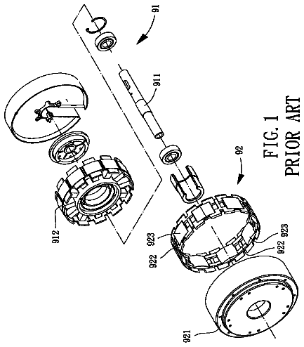
Ceiling fan motor
A ceiling fan motor includes a stator assembly and a rotor.
US 9,861,003 B2 · Assignee: US LED, Ltd. · Inventors: DeKeyser; Nicholas Joseph
Sheet 1 of 8 from the published document. All sheets in the USPTO PDF
A flexible mounting clip is configured for engaging with a circuit board for removably attaching the circuit board to a mounting surface. A rib on an arm of the mounting clip engages with an opening in the circuit board to position and hold the circuit board in place, allowing easy replacement of the circuit board without tools.
As light emitting diode (LED) lighting fixtures become more and more common, manufacturers have looked for better ways of mounting LED circuit boards in the fixtures. Conventional techniques include mechanical fasteners such as rivets or screws to secure the circuit boards to the fixture, but this has been observed to cause bowing or flexing of the circuit boards, resulting in undesirable light patterns or poor thermal conduction to the fixture. Riveting or screwing circuit boards to a fixture takes time, and quicker ways for mounting circuit boards in fixtures have been desired. In addition, considerable effort is needed to replace a circuit board that is riveted, screwed, or otherwise directly attached to the fixture, and ways to make replacement easier would be desirable.
All 8 drawing sheets from the published document, cropped to the drawing.
What the patent claimed, word for word. All of it is now free to use.
The present invention relates to the field of lighting, and in particular to a mounting clip for mounting circuit boards in LED lighting fixtures.
As light emitting diode (LED) lighting fixtures become more and more common, manufacturers have looked for better ways of mounting LED circuit boards in the fixtures. Conventional techniques include mechanical fasteners such as rivets or screws to secure the circuit boards to the fixture, but this has been observed to cause bowing or flexing of the circuit boards, resulting in undesirable light patterns or poor thermal conduction to the fixture. Riveting or screwing circuit boards to a fixture takes time, and quicker ways for mounting circuit boards in fixtures have been desired. In addition, considerable effort is needed to replace a circuit board that is riveted, screwed, or otherwise directly attached to the fixture, and ways to make replacement easier would be desirable.
The accompanying drawings, which are incorporated in and constitute a part of this specification, illustrate an implementation of apparatus and methods consistent with the present invention and, together with the detailed description, serve to explain advantages and principles consistent with the invention. In the drawings,
FIG. 1 is a top view of a mounting clip according to one embodiment.
FIG. 2 is a bottom view of the mounting clip of FIG. 1 .
FIG. 3 is a perspective view of the mounting clip of FIG. 1 .
FIG. 4 is a side view of an arm of a mounting clip according to one embodiment.
FIG. 5 is a perspective view of the underside of one arm of a mounting clip according to one embodiment.
FIG. 6 is a side view of a portion of a mounting clip according to one embodiment engaged with a circuit board.
FIG. 7 is a top view of the mounting clip of FIG. 1 engaged with a circuit board according to one embodiment.
FIG. 8 is a cutaway view of a mounting clip and two circuit boards mounted in an LED light fixture according to one embodiment.
In the following description, for purposes of explanation, numerous specific details are set forth in order to provide a thorough understanding of the invention. It will be apparent, however, to one skilled in the art that the invention may be practiced without these specific details. In other instances, structure and devices are shown in block diagram form in order to avoid obscuring the invention. References to numbers without subscripts are understood to reference all instance of subscripts corresponding to the referenced number. Moreover, the language used in this disclosure has been principally selected for readability and instructional purposes, and may not have been selected to delineate or circumscribe the inventive subject matter, resort to the claims being necessary to determine such inventive subject matter. Reference in the specification to “one embodiment” or to “an embodiment” means that a particular feature, structure, or characteristic described in connection with the embodiments is included in at least one embodiment of the invention, and multiple references to “one embodiment” or “an embodiment” should not be understood as necessarily all referring to the same embodiment.
In the following “top” is considered to be the side of an object away from a mounting surface of an LED light fixture, and “bottom” is considered to be the side of the object towards the mounting surface. However, these designations are arbitrary, and, for example, the “top” side may be closer to a surface of the earth than the “bottom” side, or in any other orientation to a surface of the earth, depending on the orientation of mounting surface of the light fixture.
Although described herein in terms of an LED light fixture application, the invention is not so limited, and may be used in any application in which circuit boards are to be attached to a surface, using mounting clips to hold the circuit boards, while allowing easy removal.
FIG. 1 is a top view of a mounting clip 100 according to one embodiment that provides an improved technique for mounting LED circuit boards in LED light fixtures, allowing easy assembly and replacement. Rather than directly attaching the LED circuit boards to the LED light fixture, mounting clips are attached to the LED light fixture and LED circuit boards can be quickly snapped into place and held in place by the mounting clip, without the bowing or flexing effects of direct mounting. Should the circuit board need to be replaced, it can be simply unclipped from the mounting clip, without needing to unscrew or remove a rivet from the circuit board. The mounting clip can remain in place for the replacement circuit board.
As illustrated in FIG. 1 , the mounting clip has four arms ( 110 A- 110 D), surrounding a central mounting member 130 which has a hole 120 formed through the mounting member 130 . Vanes 140 may extend from the mounting member 130 for structural stability as needed. Distal to the central mounting member on each arm 110 A- 110 D is a raised section 112 A- 112 D which provides room for holding the circuit board (not shown in FIG. 1 ). The mounting clip 100 may be mounted to an LED light fixture using a rivet, screw, or other mounting member extending through the hole 120 of the mounting member 130 to engage with the LED light fixture (not shown in FIG. 1 ). Any desired technique for mounting the mounting clip to the LED light fixture may be used.
In the embodiment illustrated in FIG. 1 , two opposed arms 110 A and 110 C are shorter than the other two opposed arms 110 B and 110 D. This allows a single mounting clip 100 to be used with two different inter-circuit board spacing, by engaging two circuit boards with either arms 110 A and 110 C or arms 110 B and 110 D. In some embodiments, wires or other elements may be held in place using the alternate arms of the cruciform mounting clip, for example using arms 110 A and 110 C for holding wires, while using arms 110 B and 110 D for holding the circuit board. In some embodiments, the mounting clip may be rotatably mounted, so that the inter-circuit board spacing (pitch) may be adjusted by switching between longer arms 110 B and 110 D and shorter arms 110 A and 110 C.
Although illustrated in FIG. 1 with four arms in a cruciform configuration, other numbers of arms may be used, including one, two, or any other desired number. For example, a mounting clip may use just arms 110 A and 110 C, omitting arms 110 B and 110 D. In some embodiments, the central mounting member 130 may be omitted, depending on the technique used for mounting the mounting clip 100 to the LED light fixture. Although illustrated with one pair of arms 110 being perpendicular to the other pair of arms 110 , other angles may be used as desired.
The length of the arms 110 depends on the desired inter-circuit board spacing. Different embodiments of the mounting clip 100 may be manufactured with different arm lengths. Although in FIG. 1 the opposite arms are of the same length, unequal opposed arms 110 may be used if desired. Depending on the light pattern desired, different configurations of mounting clips 100 may be used in the same LED light fixture.
FIG. 2 is a bottom view of the mounting clip 100 according to one embodiment. In one embodiment, one or more support members 220 (as illustrated, two pins 220 A and 220 B) may extend away from a surface of the bottom of the mounting clip 100 about the hole 120 . These pins may extend into the mount surface and may prevent the mounting clip from pivoting around hole 120 . Other embodiments may use differing numbers of pins, including omitting them. The pins may be any desired length or shape. Typically, the mounting clip may be manufactured using an injection molding process, but desired manufacturing technique may be used.
In one embodiment, the mounting clip may be formed of a plastic material, such as a polyether ether ketone (PEEK) plastic. Other materials may be used, including metal, as long as the material is flexible enough to allow insertion and removal of the circuit board from the raised sections 112 .
As illustrated in FIG. 2 , each arm 110 A- 110 D has a raised section 210 A- 210 D, corresponding to the raised sections 112 A- 112 D of FIG. 1 , In some embodiments, the raised sections 210 A- 210 D have an overall thickness similar to that of the rest of the arms 110 A- 110 D, but are offset from the rest of the arms 110 A- 110 D; in other embodiments the thickness of the raised section is decreased, so that the bottom surface of the raised section 210 A- 210 D is higher (relative to the mounting surface) than the bottom surface of the remainder of the arm 110 A- 110 D.
A rib 212 A- 212 B may be formed in each raised section 212 A- 212 D, extending towards the mounting surface when assembled in the LED light fixture. Typically, the ribs 212 A- 212 D are substantially rectangular, extending across the full width raised section 210 A- 210 D of the arms 110 A- 110 D, but any desired shape and size for the ribs 212 A- 212 D may be used, corresponding to a matching slot on the circuit board (not shown in FIG. 2 ). For example, instead of a rib extending across the entire width of the raised section, the ribs 212 A- 212 D may extend longitudinally along a portion of the raised sections 210 A- 212 D, or may be circular, elliptical, or of any other desired shape and orientation. Although illustrated in FIG. 2 approximately in the middle of the raised sections 210 A- 210 D, the ribs 212 A- 212 D may be formed at any desired position relative to the raised sections 210 A- 210 D. In one embodiment, the ribs 212 A- 212 B may extend from the raised sections 210 A- 210 D the full depth of the raised sections 210 A- 212 D. In other embodiments, the ribs may have any desired depth sufficient to hold a circuit board in place when engaged with the circuit board. The bottom surface of the ribs 212 A- 212 D may be flat or rounded as desired.
In some embodiments, lines 214 A- 214 D and 216 A- 216 D may extend from the bottom surface of the raised section on either side of the ribs 212 A- 212 D. Lines 214 A- 214 D and 216 A- 216 D provide contact points for the corresponding arms 110 A- 110 D of the mounting clip 100 with the printed circuit board. The lines 214 A- 214 D and 216 A- 216 D provide defined locations for the arms 110 A- 110 D to apply force to the circuit board, to ensure the circuit board is as flat as possible. The lines 214 A- 214 D and 216 A- 216 D are optional and may be omitted if desired.
FIG. 3 is a perspective view of the mounting clip of FIG. 1 according to one embodiment. In this view, the offset nature of the raised sections 112 A- 112 D relative to the base sections 310 A- 310 D is more clearly illustrated.
FIG. 4 is a side view of one of the arms 110 A according to one embodiment, illustrating a relative positioning of the base section 310 A, the raised section 112 A, and rib 212 A. Similar positioning may be found in the other arms 110 B- 110 D. However, in some embodiments, mounting clips may be formed with different relative positioning of the base and raised sections 310 A- 310 D and 112 A- 112 D, as well as the sizes, shapes, and orientations of the ribs 212 A- 212 D if desired. FIG. 5 is a perspective view from the bottom of arm 110 A, illustrating the base section 310 A, raised section 112 A, ribs 212 A, and lines 214 A and 216 A.
FIG. 6 is a side view illustrating a portion of an assembly 600 consisting of one arm 110 A of the mounting clip 100 of FIGS. 1-5 engaged with a mounting surface 610 of an LED light fixture and a circuit board 620 in partial cutaway. As illustrated in FIG. 6 , pin 220 A holds the central mounting area of the mounting clip 100 away from the mounting surface 610 , while rib 212 A engages with a slot (not visible in this view) of the circuit board 620 .
FIG. 7 , is a top view of the assembly 600 with the rib 212 A (which would normally not be visible from this angle) engaging with one of the slots 710 A- 710 C of the circuit board 620 . As illustrated in FIG. 7 , the circuit board 620 has three approximately rectangular slots formed in circuit board 620 . The slots 710 A- 710 C may extend the full depth of the circuit board or may be formed as indentations that do not go fully through the circuit board, as desired. As explained previously, the shape, size, and orientation of the slots 710 A- 710 C approximately match the shape, size, and orientation of the ribs 212 A- 212 D, allowing easy engagement with the mounting clip. Although three slots 710 A- 710 C are illustrated in FIG. 7 , any desired number of slots may be used, with longer circuit boards 620 typically having more slots than shorter ones. Other mounting clips may be attached to the LED light fixture mounting surface 610 positioned to engage with the other slots 710 A- 710 C.
FIG. 8 is a cutaway view of an LED light fixture 800 , with a rivet 810 extending through the central mounting member and attaching the mounting clip 100 to the mounting surface 610 of the LED light fixture 800 . Two circuit boards 620 A and 620 B are positioned and engaged with arms 110 A and 110 C of mounting clip 100 by flexing the end of the arm 110 A or 110 C, typically by lifting the end of the raised section 112 A and 112 C and sliding the circuit boards 620 A, 620 B under the raised sections 112 A and 112 C to engage slots 710 A and 710 C (not shown in FIG. 8 ) with the ribs 212 A and 212 C. To remove one of the circuit boards 620 A or 620 B, the reverse procedure would be followed: flex the arm 110 A or 110 C sufficiently to clear the rib 212 A or 212 C from slots 710 A or 710 C, then slide the circuit board 620 A or 620 B out.
Thus, a kit of mounting clips 100 and circuit boards 620 may be provided for mounting to LED light fixtures 800 , allowing easy and quick assembly and disassembly as needed, without a need to remove rivets, screws, or other attachment mechanisms that have previously been used to attach circuit boards 620 to mounting surfaces 610 . Although if necessary the mounting clips 100 may be removed from the mounting surface 610 and replaced or reattached, in normal operation the mounting clips 100 may remain in place once attached, which circuit boards 620 may be easily inserted or removed as needed or desired without tools.
While certain exemplary embodiments have been described in details and shown in the accompanying drawings, it is to be understood that such embodiments are merely illustrative of and not devised without departing from the basic scope thereof, which is determined by the claims that follow.
About 2,677 words. The USPTO PDF has it with every drawing.
Fees are due 3.5, 7.5 and 11.5 years after grant. This patent expired on January 2, 2026, so the fee marked "not paid" was the one that went unpaid.
MOUNTING CLIP
Filed Apr 2016 · published Oct 2017Mounting clip
Filed Apr 2016 · granted Jan 2018Earlier publications, parents and continuations. None of them can still be enforced, or this patent would not be listed.
Prior art cited by the examiner or applicant. Useful when you check your own idea for novelty.
Everything on this page comes from the documents linked above.


