Lapsed, fee not paid5 drawings
Vehicles & Drones · US 9,856,799 B1
Methods and systems for an oxygen sensor
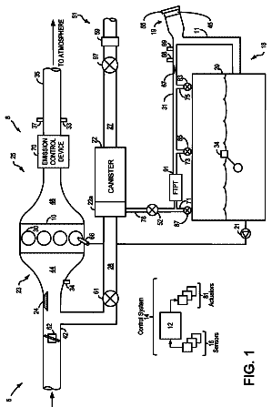
Methods and systems are provided for reducing blackening of an oxygen sensor due to voltage excursions into an over-potential region.
US 9,856,802 B2 · Assignee: Mitsubishi Electric Corporation · Inventors: Yokono; Michihisa et al.
Sheet 1 of 8 from the published document. All sheets in the USPTO PDF
There is provided a controller, for a supercharger-equipped internal combustion engine, that can accurately estimate a supercharging pressure, without providing a pressure sensor for detecting the supercharging pressure. In a controller for a supercharger-equipped internal combustion engine, a correction value for correcting a supercharging pressure estimation value is changed so that an effective opening area estimation value, estimated based on a supercharging pressure estimation value and the like, approaches a preliminarily set effective opening area default value corresponding to a throttle opening degree detection value.
The present invention relates to a controller whose control subject is an internal combustion engine equipped with a supercharger having a turbine provided in an exhaust path, a compressor that is provided at the upstream side of a throttle valve in an intake path and rotates integrally with the turbine, and a wastegate valve provided in a turbine bypass path, of the exhaust path, that bypasses the turbine.
1 of 8 drawing sheets so far from the published document, cropped to the drawing. Every sheet is in the USPTO PDF.
What the patent claimed, word for word. All of it is now free to use.
The disclosure of Japanese Patent Application No. 2015-129496 filed on Jun. 29, 2015 including its specification, claims and drawings, is incorporated herein by reference in its entirety.
The present invention relates to a controller whose control subject is an internal combustion engine equipped with a supercharger having a turbine provided in an exhaust path, a compressor that is provided at the upstream side of a throttle valve in an intake path and rotates integrally with the turbine, and a wastegate valve provided in a turbine bypass path, of the exhaust path, that bypasses the turbine.
An after-mentioned technology disclosed in Japanese Patent Application No. JP-A-2008-57339, which has been applied by the present applicant, is known, although it is a control technology for an internal combustion engine equipped with no supercharger. In the technology disclosed in JP-A-2008-57339, there is utilized a flow rate calculation equation for a throttle-type flowmeter that can represent the flow rate characteristic of a throttle valve, and based on the amount of air that passes through the throttle valve, the respective air pressures at the upstream and downstream sides of the throttle valve, and the temperature of the air, the effective opening area of the throttle valve is estimated; then, based on the result of the estimation, the throttle opening degree is learned and reflected in the control of the throttle valve opening degree.
Meanwhile, with regard to the control of a supercharger-equipped internal combustion engine, it is important to detect a supercharging pressure, which is a pressure at a position, in the intake path, that is at the downstream side of the compressor and at the upstream side of the throttle valve. However, provision of a pressure sensor for detecting a supercharging pressure results in a cost hike. Accordingly, the present applicant has developed a method of accurately estimating a supercharging pressure without providing any pressure sensor for detecting the supercharging pressure. The present applicant thought that with regard to accurate estimation of a supercharging pressure, it is important to consider the flow rate characteristic of a throttle valve. However, in the technology disclosed in JP-A-2008-57339, it is assumed that a pressure sensor for detecting the pressure (atmospheric pressure) at a position that is at the upstream side of the throttle valve is provided; thus, the technology cannot be applied to the method of estimating a supercharging pressure without providing any pressure sensor for detecting the supercharging pressure.
The present invention has been implemented in order to solve the foregoing problems; the objective thereof is to provide a controller, for a supercharger-equipped internal combustion engine, that can accurately estimate a supercharging pressure.
A controller according to the present invention is a controller whose control subject is an internal combustion engine equipped with a supercharger having a turbine provided in an exhaust path, a compressor that is provided at the upstream side of a throttle valve in an intake path and rotates integrally with the turbine, and a wastegate valve provided in a turbine bypass path, of the exhaust path, that bypasses the turbine. The controller for a supercharger-equipped internal combustion engine includes a throttle opening degree detection unit that detects a throttle opening degree, which is an opening degree of the throttle valve; an intake air amount detection unit that detects an intake air amount of the internal combustion engine; an intake air temperature detection unit that detects an intake air temperature, which is a temperature of intake air of the internal combustion engine; a manifold pressure detection unit that detects a manifold pressure, which is a pressure in an intake manifold as the intake path situated at the downstream side of the throttle valve; a supercharging pressure estimation unit that estimates a supercharging pressure, which is a pressure in the intake path situated at the downstream side of the compressor and at the upstream side of the throttle valve; and an opening area estimation unit that estimates an effective opening area of the throttle valve, based on the supercharging pressure estimation value, the manifold pressure detection value, the intake air amount detection value, and the intake air temperature detection value. The supercharging pressure estimation unit changes a correction value for correcting the supercharging pressure estimation value so that the effective opening area estimation value approaches a preliminarily set effective opening area default value corresponding to the throttle opening degree detection value, and adopts a value corrected by the correction value, as a final supercharging pressure estimation value.
The controller for a supercharger-equipped internal combustion engine according to the present invention estimates an effective opening area of the throttle valve, based on a supercharging pressure estimation value, a manifold pressure detection value, an intake air amount detection value, and an intake air temperature detection value. Based on the characteristic of the relationship between the throttle opening degree and the effective opening area default value, an estimation error in the effective opening area estimation value is determined, so that an estimation error in the supercharging pressure estimation value utilized for estimating the effective opening area can be corrected. Therefore, the supercharging pressure can accurately be estimated without providing any pressure sensor for detecting a supercharging pressure.
The foregoing and other object, features, aspects, and advantages of the present invention will become more apparent from the following detailed description of the present invention when taken in conjunction with the accompanying drawings.
FIG. 1 is a schematic configuration diagram of a supercharger-equipped internal combustion engine and a controller thereof according to Embodiment 1 of the present invention;
FIG. 2 is a block diagram of the controller for the supercharger-equipped internal combustion engine according to Embodiment 1 of the present invention;
FIG. 3 is a graph representing the relationship between the pressure ratio and the dimensionless flow rate according to Embodiment 1 of the present invention;
FIG. 4 is a graph representing the relationship between the throttle opening degree and the default value of an effective opening area according to Embodiment 1 of the present invention;
FIG. 5 is a graph for explaining prohibition or permission of a change in the correction value according to Embodiment 1 of the present invention;
FIG. 6 is a graph representing the relationship between the pressure ratio and the exhaust gas amount according to Embodiment 1 of the present invention;
FIG. 7 is a graph representing the relationship between the pressure ratio and the value of multiplication of the effective opening area by the crank rotation cycle according to Embodiment 1 of the present invention;
FIG. 8 is a graph representing the relationship between the pressure ratio and the value of multiplication of the effective opening area by the crank rotation cycle according to Embodiment 1 of the present invention;
FIG. 9 is a graph representing the relationship between the pressure ratio and the value of multiplication of the effective opening area by the crank rotation cycle according to Embodiment 1 of the present invention;
FIG. 10 is a flowchart representing the processing by the controller according to Embodiment 1 of the present invention; and
FIG. 11 is a hardware configuration diagram of the controller for the supercharger-equipped internal combustion engine according to Embodiment 1 of the present invention. DETAILED DESCRIPTION OF THE PREFERRRED EMBODIMENTS Embodiment 1
A controller 1 for an internal combustion engine 10 equipped with a supercharger 32 (hereinafter, referred to simply as the controller 1 ) according to Embodiment 1 will be explained with reference to drawings. FIG. 1 is a schematic configuration diagram of the controller 1 and the internal combustion engine 10 equipped with the supercharger 32 ; FIG. 2 is a block diagram of the controller 1 according to Embodiment 1.
At first, the configuration of the internal combustion engine 10 equipped with the supercharger 32 (hereinafter, referred to simply as the internal combustion engine 10 ) will be explained. The internal combustion engine 10 has a plurality of combustion chambers 11 . The internal combustion engine 10 has an intake path 20 for supplying air to the combustion chambers 11 and an exhaust path 30 for discharging exhaust gas from the combustion chambers 11 . The intake path 20 has an intake manifold 22 for supplying air to the respective combustion chambers 11 . A throttle valve 23 is provided at a position, in the intake path 20 , that is at the upstream side of the intake manifold 22 . The internal combustion engine 10 has the supercharger 32 . The supercharger 32 has a turbine 32 d provided in the exhaust path 30 , a compressor 32 b that is provided at the upstream side of the throttle valve 23 in the intake path 20 and rotates integrally with the turbine 32 d , and a wastegate valve 33 a that is provided at a position in a turbine bypass path 33 , of the exhaust path 30 , that bypasses the turbine 32 d.
In the exhaust path 30 , there are provided a turbine housing 32 c that contains the turbine 32 d and the turbine bypass path 33 that connects the upstream portion of the turbine housing 32 c with the downstream portion thereof so that the turbine 32 d is bypassed. The wastegate valve 33 a is provided in the turbine bypass path 33 . In the internal combustion engine 10 , there is provided a wastegate actuator 33 b that varies the opening degree of the wastegate valve 33 a so as to adjust the flow path area of the turbine bypass path 33 . A catalyst 31 is provided at the downstream side of the connection portions where the turbine bypass path 33 is connected with the exhaust path 30 .
The wastegate actuator 33 b is a positive-pressure actuator where a diaphragm is utilized. The pressure chamber of the diaphragm is connected to the intake path 20 (hereinafter, referred to as a supercharging intake path 24 ) that is at the downstream side of the compressor 32 b and at the upstream side of the throttle valve 23 ; when due to supercharging, the pressure (a supercharging pressure P2) in the supercharging intake path 24 becomes higher than the atmospheric pressure P1, the wastegate actuator 33 b can actuate the wastegate valve 33 a . In the wastegate actuator 33 b , there is provided a relief valve for adjusting the opening degree of a relief path that connects the pressure chamber of the diaphragm with the intake path 20 at the upstream side of the compressor 32 b ; the relief amount (the falling amount) of the pressure in the pressure chamber varies in accordance with the opening degree of the relief valve 36 . The relief valve 36 is a solenoid valve that is controlled by the controller 1 . The controller 1 makes the relief valve 36 adjust the relief amount; the pressure in the pressure chamber of the diaphragm to which the supercharging pressure P2 is supplied is adjusted; then, the opening degree of the wastegate valve 33 a that operates in conjunction with the diaphragm is adjusted. As Embodiment 1, in general, neither the wastegate actuator 33 b nor the wastegate valve 33 a is equipped with a detector for detecting the operating amount thereof. Accordingly, by utilizing the detection value of the pressure such as the manifold pressure Pb in the intake path 20 at the downstream side of the compressor 32 b , the control amount for the wastegate actuator 33 b (relief valve 36 ) is adjusted. In the pressure state at a time before the wastegate actuator 33 b can start to operate, i.e., in the state where the supercharging pressure P2 has not exceeded the atmospheric pressure P1, a mechanical element such as a spring contained in the wastegate actuator 33 b holds the wastegate valve 33 a at the full-closure position.
In the intake path 20 , there are provided a compressor housing 32 a for containing the compressor 32 b and a compressor bypass path 34 for connecting the intake path 20 at the upstream side of the compressor housing 32 a with the intake path 20 at the downstream side of the compressor housing 32 a so as to bypass the compressor 32 b . In the compressor bypass path 34 , there is provided an air bypass valve 34 a that opens or closes the flow path of the compressor bypass path 34 . In the intake path 20 , an intercooler 21 is provided at the downstream side of the compressor housing 32 a , and the throttle valve 23 is provided at the downstream side of the intercooler 21 .
The throttle valve 23 is opened or closed by a throttle motor (a motor for driving the throttle valve) 23 a . The opening degree of the throttle valve 23 is detected by a throttle position sensor 23 b.
The intake manifold 22 is equipped with a manifold pressure sensor 42 for detecting the manifold pressure Pb, which is the pressure of intake air in the intake manifold 22 , and an intake air temperature sensor 46 for detecting an intake air temperature Tb, which is the temperature of intake air in the intake manifold 22 .
In the exhaust path 30 , there is provided an A/F sensor 45 for detecting an air-fuel (Air/Fuel) ratio AF, which is the ratio of air to fuel in exhaust gas. An atmospheric pressure sensor 43 for detecting the atmospheric pressure P1 is provided outside the internal combustion engine 10 . In addition, the controller 1 may be configured in such a way that the atmospheric pressure sensor 43 is not provided and that based on a manifold pressure detection value Pbdt detected by the manifold pressure sensor 42 , the atmospheric pressure P1 is estimated while considering the driving state.
The configuration of the supercharger 32 will be explained. A centrifugal turbine is formed of the turbine housing 32 c and the turbine 32 d that is provided inside the turbine housing 32 and functions as a turbine wheel having a plurality of blades. A centrifugal compressor is formed of the compressor housing 32 a and the compressor 32 b that is provided inside the compressor housing 32 a and functions as a compressor wheel having a plurality of blades. The turbine 32 d and the compressor 32 b are coupled with each other by a turbine shaft 32 e in such a way as to integrally rotate on the same axis. Therefore, when exhaust gas drives and rotates the turbine 32 d , the compressor 32 b rotates at the same rotation speed as the turbine 32 d ; then, the internal combustion engine 10 is supercharged with the air from the intake path 20 . As described above, the supercharger 32 is formed of the centrifugal turbine ( 32 c , 32 d ) and the centrifugal compressor ( 32 a , 32 b ).
As the air bypass valve 34 a , a diaphragm is utilized. A diaphragm is activated by the pressure difference between the supercharging pressure P2 and the manifold pressure Pb. When the supercharging pressure P2 increases to exceed a predetermined pressure difference from the manifold pressure Pb, the diaphragm is activated and hence the air bypass valve 34 a is opened; thus, the upstream side and the downstream side of the compressor 32 b are connected. Accordingly, it is made possible to prevent mechanical damage caused by an abnormal rise of the supercharging pressure P2. The air bypass valve 34 a is provided with a switching valve 35 . The switching valve 35 can switch over the manifold pressure Pb supplied to the air bypass valve 34 a to the supercharging pressure P2. The switching valve 35 is a solenoid valve that is controlled by the controller 1 . Therefore, the controller 1 can control the operation timing of the air bypass valve 34 a . In the pressure state at a time before the air bypass valve 34 a can start to operate, i.e., in the state where the pressure difference supplied to the diaphragm is small, the air bypass valve 34 a is held at the full-closure position by the mechanical element such as a spring contained in the air bypass valve 34 a.
Next, the controller 1 will be explained. The controller is a controller whose control subject is the internal combustion engine 10 equipped with the supercharger 32 . Respective control units 70 through 85 and the like provided in the controller 1 are realized by a processing circuit included in the controller 1 . Specifically, as illustrated in FIG. 11 , the controller 1 includes, as a processing circuit, a computing processing unit (computer) 90 such as a CPU (Central Processing Unit), storage apparatuses 91 that exchange data with the computing processing unit 90 , an input circuit 92 that inputs external signals to the computing processing unit 90 , an output circuit 93 that outputs signals from the computing processing unit 90 to the outside, and the like. As the storage apparatuses 91 , there are provided a RAM (Random Access Memory) that can read data and write data from the computing processing unit 90 , a ROM (Read Only Memory) that can read data from the computing processing unit 90 , and the like. The input circuit 92 is connected with various kinds of sensors and switches and is provided with an A/D converter and the like for inputting output signals from the sensors and the switches to the computing processing unit 90 . The output circuit 93 is connected with electric loads and is provided with a driving circuit and the like for outputting a control signal to the electric loads from the computing processing unit 90 . In addition, the computing processing unit 90 runs software items (programs) stored in the storage apparatus 91 such as a ROM and collaborates with other hardware devices in the controller 1 , such as the storage apparatus 91 , the input circuit 92 , and the output circuit 93 , so that the respective functions of the control units 70 through 85 included in the controller 1 are realized.
In Embodiment 1, the input circuit 92 is connected with the throttle position sensor 23 b , a crank rotation speed sensor 40 , the manifold pressure sensor 42 , the atmospheric pressure sensor 43 , an accelerator position sensor 44 , the A/F sensor 45 , the intake air temperature sensor 46 , and the like. The output circuit 93 is connected with the throttle motor 23 a , the switching valve 35 for the air bypass valve 34 a , the relief valve 36 for the wastegate actuator 33 b , and the like. The controller 1 is connected with various kinds of unillustrated sensors, switches, actuators, and the like.
As basic control, the controller 1 calculates the fuel injection amount and the ignition timing, based on inputted output signals and the like from the various kinds of sensors so as to perform driving control of a fuel ignition apparatus, an ignition apparatus, and the like (unillustrated). Based on the output signal of the accelerator position sensor 44 and the like, the controller 1 calculates the output torque of the internal combustion engine 10 , demanded by the driver, and then controls the throttle valve 23 , the wastegate valve 33 a , and the like so that an intake air amount Qa for realizing the demanded output torque is obtained. Specifically, the controller 1 calculates a desired throttle opening degree and then performs driving control of the throttle motor 23 a so that a detection value TPdt of the throttle opening degree, detected based on the output signal of the throttle position sensor 23 b , approaches the desired throttle opening degree.
While controlling the throttle opening degree TP, the controller 1 controls the driving signal for the wastegate actuator 33 b (relief valve 36 ) so that the opening degree of the wastegate valve 33 a becomes a desired opening degree. Specifically, the controller 1 performs duty driving of the relief valve 36 , as a solenoid valve, and increases or decreases the duty ratio so as to increases or decreases the relief amount (falling amount) of the supercharging pressure P2 of the air to be supplied to the pressure chamber of the wastegate actuator 33 b . In the case where the relief valve 36 is controlled to be fully closed so that the relief amount is made minimum, the pressure in the pressure chamber becomes maximum in the control range of the relief valve 36 and the opening degree of the wastegate valve 33 a becomes maximum in the control range thereof. Accordingly, the exhaust gas amount Qex that bypasses the turbine 32 d becomes maximum and hence the exhaust gas amount Qex that is supplied to the turbine 32 d becomes minimum. As a result, there occurs a driving state in which supercharging is weakened at most. In contrast, in the case where the relief valve 36 is controlled to be fully opened so that the relief amount is made maximum, the pressure in the pressure chamber becomes minimum in the control range of the relief valve 36 and the opening degree of the wastegate valve 33 a becomes minimum in the control range thereof. Accordingly, the exhaust gas amount Qex that bypasses the turbine 32 d becomes minimum and hence the exhaust gas amount Qex that is supplied to the turbine 32 d becomes maximum. As a result, there occurs a driving state in which supercharging is strengthened at most.
The controller 1 is provided with a throttle opening degree detection unit 70 . The throttle opening degree detection unit 70 detects the throttle opening degree TP, which is the opening degree of the throttle valve 23 . The throttle opening degree detection unit 70 detects the throttle opening degree TP, based on the output signal of the throttle position sensor 23 b.
The controller 1 is provided with an intake air amount detection unit 71 . The intake air amount detection unit 71 detects the intake air amount Qa of the internal combustion engine 10 . In Embodiment 1, the intake air amount detection unit 71 is a so-called D-Jetronic type in which based on the manifold pressure detection value Pbdt, the rotation speed detection value Nedt of the internal combustion engine 10 , and the intake air temperature detection value Tbdt, the intake air amount Qa is detected. It may be allowed that the intake air amount detection unit 71 is a so-called L-Jetronic type in which based on the output signal of an air flow sensor provided in the intake path 20 , the intake air amount Qa is detected.
The controller 1 is provided with an intake air temperature detection unit 72 . The intake air temperature detection unit 72 detects the intake air temperature Tb, which is the temperature of intake air in the internal combustion engine 10 . The intake air temperature detection unit 72 detects the intake air temperature Tb, based on the output signal of the intake air temperature sensor 46 , which is inputted to the controller 1 .
The controller 1 is provided with a manifold pressure detection unit 73 . The manifold pressure detection unit 73 detects the manifold pressure Pb, which is the pressure in the intake manifold 22 as the intake path 20 at the downstream side of the throttle valve 23 . The manifold pressure detection unit 73 detects the manifold pressure Pb, based on the output signal of the manifold pressure sensor 42 .
The controller 1 is provided with a supercharging pressure estimation unit 74 . The supercharging pressure estimation unit estimates the supercharging pressure P2, which is the pressure in the intake path 20 (supercharging intake path 24 ) that is situated at the downstream side of the compressor 32 b and at the upstream side of the throttle valve 23 . The method of estimating the supercharging pressure P2, according to Embodiment 1, will be described later. The controller 1 is utilized in various kinds of control items such as the control in which based on a supercharging pressure estimation value P2es estimated by the supercharging pressure estimation unit 74 , the control amount for the wastegate actuator 33 b (relief valve 36 ) is set and the desired throttle opening degree for realizing a desired intake air amount is set.
The controller 1 is provided with an opening area estimation unit 75 . The opening area estimation unit 75 estimates an effective opening area Sth of the throttle valve 23 , based on the supercharging pressure estimation value P2es, the manifold pressure detection value Pbdt, an intake air amount detection value Qadt, and the intake air temperature detection value Tbdt.
In Embodiment 1, the opening area estimation unit 75 estimates the effective opening area Sth by use of the flow-rate-calculation theoretical formula, for a throttle-type flowmeter, that is given by the equation
and that can represent the flow rate characteristic of the throttle valve 23 . The effective opening area Sth corresponds to the value obtained by multiplying the opening area of the throttle valve 23 by a flow rate coefficient.
Qa = a 0 .Math. Sth .Math. 2 κ - 1 [ ( Pb P 2 ) 2 κ - ( Pb P 2 ) κ + 1 κ ] ( 1 )
where the intake air amount Qa is the volume flow rate [L/s] of intake air, a0 is the sonic velocity [m/s] of intake air, and κ is the specific heat ratio of intake air.
The equation
is obtained by rearranging the equation
with regard to the effective opening area Sth.
Sth = Qa a 0 .Math. σ σ = 2 κ - 1 [ ( Pb P 2 ) 2 κ - ( Pb P 2 ) κ + 1 κ ] = f ( Pb P 2 ) ( 2 )
where σ is a dimensionless flow rate that varies in accordance with the pressure ratio Pb/P2. The dimensionless flow rate σ becomes a constant value, i.e., the dimensionless flow rate σ at a time of the critical pressure ratio, when the pressure ratio Pb/P2 is the same as or smaller than the critical pressure ratio (approximately 0.528, in the case of air). The opening area estimation unit 75 calculates the dimensionless flow rate σ corresponding to the pressure ratio Pb/P2 calculated by dividing the manifold pressure detection value Pbdt by the supercharging pressure estimation value P2es, by use of a dimensionless flow rate map, as represented in FIG. 3 , in which the relationship between the pressure ratio Pb/P2 and the dimensionless flow rate σ is preliminarily set in accordance with the equation (2). Then, the opening area estimation unit calculates, as the effective opening area estimation value Sthes, a value to be obtained by dividing the intake air amount detection value Qadt by the multiplication product of the sonic velocity a0 and the dimensionless flow rate σ. By use of the sonic-velocity-calculation theoretical formula given by the equation (3), the opening area estimation unit 75 calculates the sonic velocity a0, based on the intake air temperature detection value Tbdt. By use of a sonic velocity constant map, which is a map in which the relationship between the intake air temperature Tb and the sonic velocity a0 is preliminarily set in accordance with the equation (3), the opening area estimation unit 75 calculates the sonic velocity a0 corresponding to the intake air temperature detection value Tbdt. a 0=κ.Math. R.Math.Tb
where R is a gas constant.
As described above, the opening area estimation unit 75 calculates the effective opening area estimation value Sthes, based on the supercharging pressure estimation value P2es and the like. However, if there exists an error in the supercharging pressure estimation value P2es, an error is caused in the effective opening area estimation value Sthes.
Meanwhile, the relationship between the throttle opening degree TP and the effective opening area default value Sthdf, represented in FIG. 4 , can be preliminarily determined by an experiment or the like. Specifically, the foregoing relationship can be preliminarily determined by an experiment, based on the effective opening area Sth calculated in accordance with the equation
and by use of the measurement values obtained by measurement devices such as the supercharging pressure P2 and the manifold pressure Pb measured by the pressure sensor, the intake air amount Qa measured by the flow rate sensor, and the intake air temperature Tb measured by the temperature sensor and the throttle opening degree TP at a time of the measurement. The effective opening area Sth that is preliminarily determined by an experiment or the like and set in such a manner as described above is referred to as the effective opening area default value Sthdf. In general, the effective opening area default value Sthdf is measured by use of the throttle valve 23 that is middle in the variation range of the production thereof. Whether or not there exists an error in the supercharging pressure estimation value P2es can be determined by whether or not there exists a difference between the effective opening area estimation value Sthes estimated based on the supercharging pressure estimation value P2es and the like and the effective opening area default value Sthdf corresponding to the throttle opening degree detection value TPdt. Then, the supercharging pressure estimation value P2es is corrected in such a way that the effective opening area estimation value Sthes approaches the effective opening area default value Sthdf, so that the estimation error in the supercharging pressure estimation value P2es can be reduced.
Thus, in the supercharging pressure estimation unit 74 , a correction value ΔP2 for correcting the supercharging pressure estimation value P2es is changed so that the effective opening area estimation value Sthes approaches the effective opening area default value Sthdf that corresponds to the throttle opening degree detection value TPdt and is preliminarily set, and the value corrected by the correction value ΔP2 is adopted as the final supercharging pressure estimation value P2es (P2es←P2es+ΔP2). In Embodiment 1, the supercharging pressure estimation unit 74 is provided with a correction value calculation unit 83 for calculating the correction value ΔP2.
This configuration makes it possible that on the basis of the characteristic of the relationship between the throttle opening degree TP and the effective opening area default value Sthdf, an estimation error in the effective opening area estimation value Sthes estimated based on the supercharging pressure estimation value P2es is determined so that the estimation error in the supercharging pressure estimation value P2es utilized for calculation of the effective opening area estimation value Sthes is corrected.
The correction value calculation unit 83 increases the corrected supercharging pressure estimation value P2es by increasing the correction value ΔP2 when the effective opening area estimation value Sthes is larger than the effective opening area default value Sthdf, and decreases the corrected supercharging pressure estimation value P2es by decreasing the correction value ΔP2 when the effective opening area estimation value Sthes is smaller than the effective opening area default value Sthdf.
In the case where the effective opening area estimation value Sthes is larger than the effective opening area default value Sthdf, it is conceivable from the equation
that the dimensionless flow rate σ is smaller than its correct value, assuming that the intake air amount detection value Qadt and the sonic velocity a0 are correct. In the case where the dimensionless flow rate σ is smaller than its correct value, it is conceivable from FIG. 3 that the pressure ratio Pb/P2 is larger than its correct value; therefore, assuming that the manifold pressure detection value Pbdt is correct, it is conceivable that the supercharging pressure estimation value P2es is smaller than it correct value. Thus, as the foregoing configuration, in the case where the effective opening area estimation value Sthes is larger than the effective opening area default value Sthdf, the corrected supercharging pressure estimation value P2es is increased by increasing the correction value ΔP2, so that the estimation error in the supercharging pressure estimation value P2es can be reduced. In contrast, in the case where the effective opening area estimation value Sthes is smaller than the effective opening area default value Sthdf, it is conceivable that the supercharging pressure estimation value P2es is larger than its correct value. Accordingly, in the foregoing configuration, the estimation error in the supercharging pressure estimation value P2es can be reduced by decreasing the correction value ΔP2 so as to decrease the corrected supercharging pressure estimation value P2es.
In Embodiment 1, the controller 1 is provided with an estimation throttle opening degree calculation unit 77 . By use of an opening area default value map, as represented in FIG. 4 , in which the relationship between the throttle opening degree TP and the effective opening area default value Sthdf is preliminarily set, the estimation throttle opening degree calculation unit 77 calculates an estimation throttle opening degree TPes, which is the throttle opening degree TP corresponding to the effective opening area estimation value Sthes. Then, the correction value calculation unit 83 changes the correction value ΔP2 so that the estimation throttle opening degree TPes approaches the throttle opening degree detection value TPdt.
As described above, the effective opening area estimation value Sthes estimated based on the supercharging pressure estimation value P2es and the like is converted into the estimation throttle opening degree TPes, which is the corresponding throttle opening degree, by use of the opening area default value map in which the relationship between the throttle opening degree TP and the effective opening area default value Sthdf is preliminarily set; the correction value ΔP2 is changed so that the estimation throttle opening degree TPes approaches the throttle opening degree detection value TPdt. As a result, the supercharging pressure estimation value P2es can be corrected so that the effective opening area estimation value Sthes approaches the effective opening area default value Sthdf corresponding to the throttle opening degree detection value TPdt. In other words, an estimation error in the effective opening area Sth is converted into an error based on the throttle opening degree by use of the opening area default value map and is utilized in processing a change in the correction value ΔP2.
The correction value calculation unit 83 increases the corrected supercharging pressure estimation value P2es by increasing the correction value ΔP2 when the throttle opening degree detection value TPdt is smaller than the estimation throttle opening degree TPes, and decreases the corrected supercharging pressure estimation value P2es by decreasing the correction value ΔP2 when the throttle opening degree detection value TPdt is larger than the estimation throttle opening degree TPes.
As represented in FIG. 4 , when the effective opening area estimation value Sthes is larger than the effective opening area default value Sthdf, the throttle opening degree detection value TPdt becomes smaller than the estimation throttle opening degree TPes. In addition, in the case where the effective opening area estimation value Sthes is larger than the effective opening area default value Sthdf, it is conceivable, as described above, that the supercharging pressure estimation value P2es is smaller than its correct value. Thus, in the foregoing configuration, in the case where the throttle opening degree detection value TPdt is smaller than the estimation throttle opening degree TPes, the corrected supercharging pressure estimation value P2es is increased by increasing the correction value ΔP2, so that the estimation error in the supercharging pressure estimation value P2es can be reduced. In contrast, in the case where the throttle opening degree detection value TPdt is larger than the estimation throttle opening degree TPes, it is conceivable that supercharging pressure estimation value P2es is larger than its correct value; therefore, as in the foregoing configuration, the estimation error in the supercharging pressure estimation value P2es can be reduced by decreasing the correction value ΔP2 so as to decrease the corrected supercharging pressure estimation value P2es.
In Embodiment 1, the correction value calculation unit 83 increases or decreases the correction value ΔP2 by a preliminarily set changing amount P2chg. Δ P 2( n )=Δ P 2( n −1)+ P 2 chg or Δ P 2( n )=Δ P 2( n −1)− P 2 chg
where (n) denotes the value in the present calculation cycle, and (n−1) denotes the value in the immediately previous calculation cycle.
In order to prevent the correction value ΔP2 from changing in a rapid and abrupt manner, the changing amount P2chg is set to a value that is the same as or smaller than 1 [kPa], although depending on the setting of the calculation cycle.
In Embodiment 1, as represented in FIG. 5 , the correction value calculation unit 83 permits the correction value ΔP2 to change when the throttle opening degree detection value TPdt is out of a preliminarily set prohibition opening degree range Rtp including the estimation throttle opening degree TPes, and prohibits the correction value ΔP2 from changing when the throttle opening degree detection value TPdt is within the prohibition opening degree range Rtp.
In the case where the difference between the throttle opening degree detection value TPdt and the estimation throttle opening degree TPes is large, it can be determined that the difference is caused not by a fluctuation in the flow rate characteristic (the relationship between the throttle opening degree TP and the effective opening area Sth) of the throttle valve 23 due to the valve difference resulted from production variations, aging deterioration, or the like of the throttle valve 23 but by an error in the supercharging pressure estimation value P2es. The width of the fluctuation in the flow rate characteristic of the throttle valve 23 , caused by production variations, aging deterioration, or the like, can preliminarily be set based on the tolerances, actually measured values, or the like; therefore, the prohibition opening degree range Rtp can preliminarily be set by considering the width of the fluctuation caused by production variations, aging deterioration, or the like. Accordingly, when the throttle opening degree detection value TPdt is out of the prohibition opening degree range Rtp, it is determined that an estimation error exists in the supercharging pressure estimation value P2es and the correction value ΔP2 is permitted to change, and when the throttle opening degree detection value TPdt is within the prohibition opening degree range Rtp, it is determined that a fluctuation exists in the flow rate characteristic of the throttle valve 23 and the correction value ΔP2 is prohibited from changing; as a result, the accuracy of correcting the supercharging pressure P2 can be raised.
In Embodiment 1, as represented in FIG. 5 , the correction value calculation unit 83 sets, as the prohibition opening degree range Rtp, a prohibition upper limit value to be obtained by adding a preliminarily set value to the estimation throttle opening degree TPes and a prohibition lower limit value to be obtained by subtracting a preliminarily set value from the estimation throttle opening degree TPes. Then, the correction value calculation unit 83 prohibits the correction value ΔP2 from changing when the throttle opening degree detection value TPdt is between the prohibition upper limit value and the prohibition lower limit value, and permits the correction value ΔP2 to change when the throttle opening degree detection value TPdt is larger than the prohibition upper limit value or smaller than the prohibition lower limit value.
The description continues in the full USPTO document.
About 6,633 words. The USPTO PDF has it with every drawing.
Fees are due 3.5, 7.5 and 11.5 years after grant. This patent expired on January 2, 2026, so the fee marked "not paid" was the one that went unpaid.
CONTROLLER FOR SUPERCHARGER-EQUIPPED INTERNAL COMBUSTION ENGINE
Filed Dec 2015 · published Dec 2016Controller for supercharger-equipped internal combustion engine
Filed Dec 2015 · granted Jan 2018Earlier publications, parents and continuations. None of them can still be enforced, or this patent would not be listed.
Prior art cited by the examiner or applicant. Useful when you check your own idea for novelty.
Everything on this page comes from the documents linked above.