Background of the invention
Field of the Invention
One disclosed aspect of the embodiments relates to an inkjet recording apparatus and an inkjet recording method.
Description of the Related Art
Inkjet recording apparatuses that record an image by using a recording head are known. The recording heads of such inkjet recording apparatuses includes a recording element array in which a plurality of recording elements that generate energy used to eject ink are arranged. It is generally known that a driving pulse is applied to the plurality of recording elements included in the recording head of such inkjet recording apparatuses to give thermal energy to ink and form a bubble in the ink and consequently the ink is ejected by pressure caused by the bubble.
It is also known that the longer the recording head is used, the lower the performance of the recording head becomes. Ultimately, the recording head reaches the end of its life, and the performance of the recording head sometimes degrades to an unusable level. In such a case, the recording head with the degraded performance is replaced with a new recording head. Regarding the performance degradation of the recording head, for example, Japanese Patent Laid-Open No. 2007-168296 discloses a technique in which the total number of times each of recording elements included in a recording head has been driven is counted and it is determined that the recording head has reached the end of its life if the total number of times counted for any one of the recording elements exceeds a predetermined threshold.
The technique disclosed in Japanese Patent Laid-Open No. 2007-168296 makes it possible to determine whether the recording head has reached the end of its life but fails to extend the life of the recording head. Accordingly, the frequency with which the user replaces the recording head may increase.
Summary of the invention
An embodiment has been made in view of the above issue and provides a recording technique that extends the life of the recording head.
An aspect of the embodiments provides an inkjet recording apparatus that records an image by ejecting ink onto a recording medium. The inkjet recording apparatus includes a recording head, a first obtaining unit, a determining unit, and a controller. The recording head includes a first recording element array and a second recording element array. The first recording element array includes a plurality of recording elements configured to produce thermal energy used to eject ink of a first color, and the second recording element array includes a plurality of recording elements configured to produce thermal energy used to eject ink of a second color different from the first color. The first obtaining unit obtains first information for each of the first and second recording element arrays. The first information is information regarding a total number of times the plurality of recording elements included in the corresponding one of the first and second recording element arrays have been driven since attachment of the recording head to the inkjet recording apparatus. The determining unit determines, for each of the first and second recording element arrays, a driving pulse to be applied to the plurality of recording elements included in the corresponding one of the first and second recording element arrays on the basis of the first information obtained by the first obtaining unit. The controller controls, for each of the first and second recording element arrays, driving of the plurality of recording elements included in the corresponding one of the first and second recording element arrays so as to eject the ink by applying the driving pulse determined by the determining unit to the plurality of recording elements included in the corresponding one of the first and second recording element arrays. The determining unit determines, (i-1) when the total number of times indicated by the first information for the first recording element array is a first value, a first driving pulse as the driving pulse to be applied to the first recording element array, (i-2) when the total number of times indicated by the first information for the first recording element array is a second value larger than the first value, a second driving pulse as the driving pulse to be applied to the first recording element array, the second diving pulse having a pulse width different from that of the first driving pulse, (ii-1) when the total number of times indicated by the first information for the second recording element array is the first value, a third driving pulse as the driving pulse to be applied to the second recording element array, and (ii-2) when the total number of times indicated by the first information for the second recording element array is the second value, a fourth driving pulse as the driving pulse to be applied to the second recording element array, the fourth driving pulse having a pulse width different from that of the second driving pulse and that of the third driving pulse.
Further features of the disclosure will become apparent from the following description of exemplary embodiments with reference to the attached drawings.
Brief description of the drawings
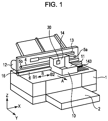
FIG. 1 is a perspective view of an inkjet recording apparatus according to a first exemplary embodiment.
FIG. 2 is a schematic view of a recording head according to the first exemplary embodiment.
FIGS. 3A to 3C are perspective and cross-sectional views of the recording head according to the first exemplary embodiment.
FIG. 4 is a diagram illustrating a recording control system according to the first exemplary embodiment.
FIG. 5 is a diagram illustrating a data processing process according to the first exemplary embodiment.
FIGS. 6A and 6B are diagrams illustrating a correlation between ink temperature and an amount of ejected ink and a correlation between a driving pulse and an amount of ejected ink.
FIG. 7 is a diagram illustrating a driving pulse.
FIGS. 8A and 8B are diagrams for describing general driving pulse control.
FIG. 9 is a diagram illustrating a correlation between temperature and an amount of ejected ink obtained when driving pulse control is performed.
FIGS. 10A to 10C are schematic views for describing how a recording element wears as the driving count increases.
FIGS. 11A to 11C are schematic views for describing a mechanism for reducing the wear of the recording element.
FIG. 12 is a flowchart illustrating driving pulse control according to the first exemplary embodiment.
FIGS. 13A to 13C are diagrams each illustrating a pulse shift table according to the first exemplary embodiment.
FIG. 14 is a diagram indicating which pulse shift table is to be used for each recording element array in the first exemplary embodiment.
FIG. 15 is a schematic view illustrating a correlation between the total driving count and driving energy.
FIGS. 16A to 16C are diagrams each illustrating a pulse shift table according to a first modification.
FIG. 17 is a schematic view illustrating a correlation between the total driving count and driving energy.
FIGS. 18A to 18C are diagrams each illustrating a pulse shift table according to a second modification.
FIG. 19 is a schematic view illustrating a correlation between the total driving count and driving energy.
FIG. 20 is a schematic view illustrating a correlation between the total driving count and driving energy.
FIG. 21 is a schematic view illustrating a correlation between the total driving count and driving energy.
Description of the embodiments
A first exemplary embodiment will be described in detail below with reference to the accompanying drawings. First Exemplary Embodiment
FIG. 1 illustrates the appearance of an inkjet recording apparatus (hereinafter, also referred to as a printer) according to the first exemplary embodiment. The inkjet recording apparatus is a so-called serial-scan-type printer and records an image by causing a recording head to scan in a direction (X direction) perpendicular to a direction (Y direction) in which a recording medium P is conveyed.
An overview of a configuration and a recording operation of this inkjet recording apparatus will be described with reference to FIG. 1 . The recording medium P is conveyed in the Y direction by a conveyance roller, which is driven by a conveyance motor (not illustrated) with a gear interposed therebetween, from a spool 6 that holds the recording medium P. A carriage motor (not illustrated) causes a carriage unit 2 to scan along a guide shaft 8 , which extends in the X direction, at a predetermined conveyance position. During this scan, an ejection operation is performed at ejection ports of a recording head (described later) attachable to the carriage unit 2 at timings based on a position signal obtained by an encoder 7 , and recording is performed in a band having a predetermined width corresponding to a range where the ejection ports are arranged. In the first exemplary embodiment, scanning is performed at a scan speed of 40 inches per second and the ejection operation is performed at a resolution of 600 dpi ( 1/600 inches). The recording medium P is then conveyed, and recording is performed for a subsequent band having the predetermined width.
Such a printer may record an image in a unit region of a recording medium in one scan (so-called single-pass recording) or in multiple scans (so-called multi-pass recording). In the case of single-pass recording, the recording medium P may be conveyed by an amount equal to the width of the band during each scan. In the case of multi-pass recording, the recording medium P is not conveyed during each scan; instead, the recording medium P may be conveyed by an amount approximately equivalent to one band relative to the unit region after the scan has been performed for the unit region of the recording medium a plurality of times. There is also another multi-pass recording method. Specifically, data is recorded after being thinned out using a predetermined mask pattern for each scan, paper is then fed by an amount approximately equivalent to a 1/n-th of a band, and the scan is then performed again. In this way, an image is completed by performing the scan and conveying operation a plurality of times (n times) in which different nozzles are used to perform recording in the unit region of the recording medium P each time.
A carriage belt can be used to transmit driving power from the carriage motor to the carriage unit 2 . As an alternative to the carriage belt, another driving system, for example, a system including a leadscrew that is rotationally driven by the carriage motor and extends in the X direction and an engaging portion that is included in the carriage unit 2 and engages with a groove of the leadscrew, may be used.
The fed recording medium P is nipped and conveyed by a sheet feed roller and a pinch roller and is guided to a recording position on a platen 4 (a main scanning region of the recording head). Since a face of the recording head is usually capped in a non-operation state, the cap is removed prior to recording to prepare the recording head or the carriage unit 2 for scanning. Then, after data of one scan has been accumulated in a buffer, the carriage motor causes the carriage unit 2 to scan to perform recording in the above-described manner.
The recording head is connected to one of terminals of a flexible wiring substrate 19 used to supply signals, such as a driving pulse for ejection driving and a head temperature adjustment signal. The other terminal of the flexible wiring substrate 19 is connected to a controller (not illustrated) including control circuitry, such as a central processing unit (CPU) that controls the printer. In addition, a thermistor (not illustrated), which is a temperature sensor that detects an ambient temperature in the inkjet recording apparatus, is also provided in the vicinity of the controller.
FIG. 2 is a perspective view schematically illustrating a recording head 9 according to the first exemplary embodiment.
The recording head 9 includes a joint portion 25 . An ink supply tube is connected to the joint portion 25 .
Two recording element substrates 10 a and 10 b formed of semiconductors and the like are attached to an ejection port surface, which is a surface of the recording head 9 that opposes the recording medium P. Each of the recording element substrates 10 a and 10 b includes ejection port arrays extending in a Y direction perpendicular to an X direction. Specifically, the recording element substrate 10 a includes an ejection port array 11 from which black (Bk) ink is ejected, an ejection port array 12 from which cyan (C) ink is ejected, an ejection port array 13 from which magenta (M) ink is ejected, and an ejection port array 14 from which yellow (Y) ink is ejected. The ejection port arrays 11 to 14 are arranged side by side in the X direction. The recording element substrate 10 b includes an ejection port array 15 from which gray (G) ink is ejected, an ejection port array 16 from which red (R) ink is ejected, an ejection port array 17 from which blue (B) ink is ejected, and an ejection port array 18 from which clear (Cl) ink is ejected. The ejection port arrays 15 to 18 are arranged side by side in the X direction.
Each of the cyan ink, the magenta ink, the yellow ink, the red ink, and the blue ink contains a pigment of the color as its colorant. Each of the black ink and the gray ink contains carbon black, which is a black pigment, as its colorant. The concentration of carbon black in the grey ink is adjusted to be lower than the concentration of carbon black in the black ink. The clear ink is ink for improving an image characteristic of the color inks when being applied on the layers of the color inks on the recording medium and contains no colorant.
As described below, recording element arrays are disposed at positions on the recording element substrates 10 a and 10 b opposing the respective ejection port arrays 11 to 18 . For ease of explanation, the recording element arrays disposed at positions opposing the ejection port arrays 11 to 18 are referred to as recording element arrays 11 x to 18 x , respectively.
The recording element substrates 10 a and 10 b are fixed to a support member 300 , composed of alumina, resin, or the like, by an adhesive. The recording element substrates 10 a and 10 b are electrically connected to an electric wiring member 600 having wirings and communicate with the recording head 9 via the electric wiring member 600 by using a signal.
FIG. 3A is a perspective view obtained when the recording element substrate 10 b is viewed from a direction perpendicular to the X-Y plane. FIG. 3B is a cross-sectional view taken along line IIIB-IIIB illustrated in FIG. 3 A and obtained when a cross-sectional portion of the recording element substrate 10 b near the ejection port array 15 is viewed from a downstream side in the Y direction. FIGS. 3A and 3B illustrate the individual components at a dimension ratio different from the actual dimension ratio for ease of illustration. The actual dimensions of the recording element substrate 10 b are 9.55 mm in the X direction and 39.0 mm in the Y direction. In addition, FIG. 3C is a partially enlarged view of a recording element 34 .
Each of the ejection port arrays 11 to 18 according to the first exemplary embodiment includes two lines of ejection ports. Each of the two lines includes 768 ejection ports 30 , which are arranged in the Y direction (arrangement direction) in the opposing lines with shifted from each other by one dot at 1200 dpi (dots/inch). In this way, 1536 ejection ports 30 and 1536 recording elements 34 (also referred to as main heaters), which are electro-thermal conversion elements, opposing the ejection ports 30 are arranged in the Y direction (predetermined direction). Note that, in the first exemplary embodiment, 1200 dpi is equivalent to approximately 0.02 mm. Thermal energy used to eject ink from the ejection ports 30 can be produced by applying a driving pulse to the recording elements 34 . Although the case of using electro-thermal conversion elements as the recording elements 34 has been described, piezoelectric elements or the like may be used as the recording elements 34 .
For ease of explanation, the ejection port 30 and the recording element 34 located on the most downstream side in the Y direction, among the 1536 ejection ports 30 and the 1536 recording elements 34 , are collectively assigned No. 0 . In addition, the ejection port 30 and the recording element 34 located on the immediately upstream side of the pair No. 0 in the Y direction is assigned No. 1 . Likewise, No. 2 to No. 1534 are assigned. The ejection port 30 and the recording element 34 located on the most upstream side in the Y direction are collectively assigned No. 1535 .
The recording element substrate 10 b includes nine diode sensors S 1 to S 9 , which serve as temperature sensors that detect ink temperature near the respective recording elements 34 .
Two diode sensors S 1 and S 6 , among the diode sensors S 1 to S 9 , are disposed near one of ends of the ejection port arrays 15 to 18 in the Y direction. Specifically, the diode sensors S 1 and S 6 are disposed to be spaced apart from the ejection ports 30 located at one end in the Y direction by 0.2 mm. The diode sensor S 1 is disposed between the ejection port arrays 15 and 16 in the X direction, and the diode sensor S 6 is disposed between the ejection port arrays 17 and 18 in the X direction.
Two diode sensors S 2 and S 7 are disposed near the other ends of the ejection port arrays 15 to 18 in the Y direction. The diode sensor S 2 is disposed between the ejection port arrays 15 and 16 in the X direction, and the diode sensor S 7 is disposed between the ejection port arrays 17 and 18 in the X direction. Specifically, the diode sensors S 2 and S 7 are disposed to be spaced apart from the ejection ports 30 at the other end in the Y direction by 0.2 mm.
Further, five diode sensors S 3 , S 4 , S 5 , S 8 , and S 9 are disposed at the middle part of the ejection port arrays 15 and 18 in the Y direction. The diode sensor S 4 is disposed between the ejection port arrays 15 and 16 in the X direction. The diode sensor S 5 is disposed between the ejection port arrays 16 and 17 in the X direction. The diode sensor S 8 is disposed between the ejection port arrays 17 and 18 in the X direction. The diode sensor S 3 is disposed on the outer side of the ejection port array 15 in the X direction. The diode sensor S 9 is disposed on the outer side of the ejection port array 18 in the X direction.
In the first exemplary embodiment, the temperature of the recording element substrate 10 b is treated as the temperature of ink because the temperature of the ink in the ejection port 30 near each of the diode sensors S 1 to S 9 is substantially equal to the temperature of the recording element substrate 10 b at the position where the diode sensor is disposed.
The recording element substrate 10 b includes heating elements (hereinafter, also referred to as sub-heaters) 19 a and 19 b that heat the ink in the ejection ports 30 to increase the temperature. The heating element 19 a is formed of a continuous member such that the ejection port array 15 is surrounded by the heating element 19 a from the side where the diode sensor S 3 is disposed in the X direction. Likewise, the heating element 19 b is formed of a continuous member such that the ejection port array 18 is surrounded by the heating element 19 b from the side where the diode sensor S 9 is disposed in the X direction. Note that the heating elements 19 a and 19 b are spaced apart from the ejection port arrays 15 and 18 by 1.2 mm on the outer side of the ejection port arrays 15 and 18 in the X direction, respectively, and are spaced apart from the diode sensors S 1 , S 2 , S 6 , and S 7 by 0.2 mm on the outer side of the diode sensors S 1 , S 2 , S 6 , and S 7 .
The recording element substrate 10 b includes a substrate 31 including various circuits disposed thereon and an ejection port member 35 composed of a resin as well as the diode sensors S 1 to S 9 and the sub-heaters 19 a and 19 b . A common ink chamber 33 is disposed between the substrate 31 and the ejection port member 35 . The common ink chamber 33 communicates with an ink supply port 32 . An ink channel 36 extends from the common ink chamber 33 . The ink channel 36 communicates with the ejection port 30 formed in the ejection port member 35 . The ink channel 36 includes a bubble formation chamber 38 at its end portion near the ejection port 30 . The bubble formation chamber 38 includes the recording element (main heater) 34 at a position opposing the ejection port 30 . In addition, a nozzle filter 37 is disposed between the ink channel 36 and the common ink chamber 33 .
As illustrated in FIG. 3C , a heat accumulation layer 401 , a heating material layer 402 , and a pair of electrode layers 403 are stacked on a substrate 400 composed of silicon and including driving elements, such as transistors, thereon. The heat accumulation layer 401 can be formed using an insulating material mainly composed of silicon. The heating material layer 402 can be formed using a material, such as TaSiN, that produces heat when being supplied with electric power. The pair of electrode layers 403 can be formed using aluminum or the like serving as an electrode to which electric power is supplied. The heating material layer 402 located between the pair of electrode layers 403 is used as the recording element 34 .
An insulating layer 404 formed using an insulating material mainly composed of silicon is stacked on the heating material layer 402 and the pair of electrode layers 403 to protect the recording element 34 from ink or the like. Further, a protection layer 405 formed using a metal material, such as Ta, is disposed on a portion of the insulating layer 404 corresponding to the recording element 34 in order to protect the recording element 34 from cavitation caused when a bubble vanishes.
The ink supplied to the recording head 9 through the joint portion 25 from the ink supply channel of the inkjet recording apparatus is transported to the ink supply port 32 of the recording element substrate 10 b through an ink channel (not illustrated) formed in the support member 300 inside the recording head 9 . The ink is then transported to the upper side of the recording element 34 through the ink channel 36 .
A driving pulse determined in a manner described later is applied to the recording element 34 in accordance with recording data received from the inkjet recording apparatus, whereby the recording element 34 is driven and produces heat. The resulting thermal energy causes the ink on the recording element 34 to start film boiling, that is, changes the state of the ink to form a bubble. The ink is ejected from the ejection port 30 by pressure of the bubble thus formed. In this way, a recording operation is performed.
Although the recording element substrate 10 b has been described in detail here, the recording element substrate 10 a also has a similar configuration.
In the first exemplary embodiment, a representative temperature is calculated for each of the recording element arrays 15 x to 18 x on the basis of a temperature detected by a different combination of diode sensors from among the diode sensors S 1 to S 9 , and driving pulse control (described later) is performed on the basis of the representative temperature calculated for each recording element array. Specifically, when driving pulse control is performed for the recording element array 15 x , the average of temperatures detected by four diode sensors S 1 , S 2 , S 3 , and S 4 that surround the recording element array 15 x is set as the representative temperature. When driving pulse control is performed for the recording element array 16 x , the average of temperatures detected by four diode sensors S 1 , S 2 , S 4 , and S 5 that surround the recording element array 16 x is set as the representative temperature. When driving pulse control is performed for the recording element array 17 x , the average of temperatures detected by four diode sensors S 5 , S 6 , S 7 , and S 8 that surround the recording element array 17 x is set as the representative temperature. When driving pulse control is performed for the recording element array 18 x , the average of temperatures detected by four diode sensors S 6 , S 7 , S 8 , and S 9 that surround the recording element array 18 x is set as the representative temperature.
Note that the representative temperature calculation method is not limited to the above method. For example, the representative temperature may be calculated by using the largest value of the temperatures detected by four diode sensors that surround each of the recording element arrays 15 x to 18 x . Alternatively, the representative temperature may be calculated for each of the recording element arrays 15 x to 18 x by using an average of the temperatures detected by the nine diode sensors S 1 to S 9 included in the recording element substrate 10 b . Further, the recording head 9 need not include a plurality of diode sensors in the first exemplary embodiment unlike FIG. 3A and is just required to include at least one diode sensor.
FIG. 4 is a block diagram illustrating a configuration of a control system installed in the inkjet recording apparatus according to the first exemplary embodiment. A main controller 100 includes a CPU 101 that performs processing operations, such as computation, control, determination, and setup. The main controller 100 also includes a read-only memory (ROM) 102 , a random access memory (RAM) 103 , and an input/output (I/O) port 104 . The ROM 102 functions as a memory that stores a control program and other programs to be executed by the CPU 101 . The RAM 103 is used as a buffer that stores binary recording data indicating whether to eject ink and as a workspace during processing performed by the CPU 101 . The RAM 103 is also used as a memory that stores information regarding an amount of ink remaining in a main tank before and after a recording operation and a free space in a sub-tank. A conveyance motor (LF motor) 113 that drives the conveyance roller, a carriage motor (CR motor) 114 , and various driving circuits 105 , 106 , 107 , and 108 that drive the recording head 9 , a recovery processing device 120 , and so on are connected to the I/O port 104 . These driving circuits 105 , 106 , 107 , and 108 are controlled by the main controller 100 . Various sensors, such as the diode sensors S 1 to S 9 that detect temperature of the recording head 9 , an encoder sensor 111 fixed to the carriage unit 2 , and a thermistor 121 that detects ambient temperature (environment temperature) in the inkjet recording apparatus are connected to the I/O port 104 . The main controller 100 is connected to a host computer 115 via an interface circuit 110 .
The driving circuit 107 , which functions as a signal transmission unit, transmits a driving pulse to be applied and recording data used for recording to the recording head 9 . The driving pulse and the recording data are transmitted via the flexible wiring substrate 19 described above.
A recovery processing counter 116 counts the number of times the recording elements have been driven during a so-called recovery process in which ink is compulsorily ejected from the recording head 9 by the recovery processing device 120 . An auxiliary ejection counter 117 counts the number of times the recording elements have been driven for auxiliary ejection that is performed before recording is started, during recording, and after recording is finished. A borderless ink counter 118 counts the number of times the recording elements have been driven when ink is ejected to outside of the recording region of the recording medium during borderless recording. An ejected dot counter 119 counts the number of times the recording elements have been driven during recording.
The sum of the counted values obtained by these counters 116 to 119 is stored in an electrically erasable programmable ROM (EEPROM) 122 as a total number of times the recording elements included in each recording element array have been driven (hereinafter, referred to as a total driving count) since attachment of the recording head 9 to the inkjet recording apparatus. Note that the total driving count of the recording elements is calculated for each recording element array in the first exemplary embodiment.
The EEPROM 122 is capable of storing various kinds of information in addition to the total driving counts of the recording elements.
FIG. 5 is a flowchart describing an image data processing process according to the first exemplary embodiment.
Image data to be recorded by an inkjet recording apparatus 1000 is created by using an application J 101 of the host computer 115 . When recording is performed, the image data created by using the application J 101 is transferred to a printer driver 1153 . The printer driver 1153 performs pre-processing J 0002 , post-processing J 0003 , γ correction J 0004 , and binarization processing J 0005 on the created image data.
During the pre-processing J 0002 , color gamut conversion is performed to convert a color gamut of a display of the host computer 115 to a color gamut of the inkjet recording apparatus 1000 . Specifically, image data (R, G, B) in which R, G, and B each represented using 8 bits are converted into 8-bit data (R, G, B) in the color gamut of the inkjet recording apparatus 1000 by using a three-dimensional lookup table.
During the post-processing J 0003 , the color that reproduces the converted color gamut is separated into a color gamut of inks. Specifically, processing is performed to determine 8-bit data (image data) corresponding to a combination of inks used to reproduce the color represented by the 8-bit data (R, G, B) in the color gamut of the inkjet recording apparatus 1000 obtained by the pre-processing J 0002 .
During the γ correction J 0004 , γ correction is performed on each 8-bit data (image data) obtained by the color separation. A conversion is performed such that each 8-bit data obtained by the post-processing J 0003 is linearly associated with a gradation characteristic of the inkjet recording apparatus 1000 to determine 8-bit data (correction data) corresponding to the combination of inks.
During the binarization processing J 0005 , binarization processing is performed in which each 8-bit data (correction data) obtained by the γ correction J 0004 is converted into 1-bit data and binary data is generated. A density pattern method, a dithering method, an error diffusion method, or the like is suitably used as the binarization method.
The data thus generated is supplied to the inkjet recording apparatus 1000 . During mask data conversion processing J 0008 , the supplied data is converted into recording data indicating whether to eject ink, by using the binary data created by the binarization processing J 0005 and a mask pattern stored on the ROM 102 . This mask pattern is created by arranging recording-permitted pixels for which ejection of ink is permitted and non-recording-permitted pixels for which ejection of ink is not permitted in a specific pattern. Note that the mask pattern used during the mask data conversion processing J 0008 is stored on a predetermined memory in the inkjet recording apparatus 1000 in advance. For example, the mask pattern may be stored on the ROM 102 described above, and the supplied data may be converted into the recording data by the CPU 101 by using this mask pattern.
The recording data obtained by the mask data conversion processing J 0008 is supplied to the head driving circuit 107 (J 0009 ) and the recording head 9 (J 0010 ). In accordance with this recording data, inks are ejected onto the recording medium P from the respective ejection ports 30 arranged in the recording head 9 .
Driving of the motors, the recording head 9 , and other components is controlled on the basis of the recording data created through the various kinds of processing described above and a recording operation is performed.
General Driving Pulse Control
During so-called driving pulse control, one driving pulse is selected from among a plurality of driving pulses in accordance with ink temperature during a recording operation and is applied to the recording elements 34 to cause the recording elements 34 to produce heat, and ink is ejected by using the resulting thermal energy. A generic example of such driving pulse control will be described in detail below.
In the first exemplary embodiment, a so-called double pulse including a pre-pulse and a main pulse is used as a driving pulse to be applied.
FIG. 7 is a diagram illustrating the aforementioned double pulse. In FIG. 7 , Vop denotes a driving voltage, P 1 denotes a pulse width of the pre-pulse, P 2 denotes a time interval, and P 3 denotes a pulse width of the main pulse. Since ink ejection control is performed by controlling the pulse width P 1 of the pre-pulse, the pre-pulse plays an important role.
The pre-pulse is a pulse to be applied mainly in order to increase ink temperature near the recording elements to cause bubble formation more easily. The pulse width P 1 of the pre-pulse is set to a value smaller than or equal to a pulse width that produces energy smaller than energy at a boundary where a bubble is formed in the ink.
The time interval P 2 is a predetermined time period provided between the pre-pulse and the main-pulse. The time interval P 2 is set such that heat produced by application of the pre-pulse is sufficiently transferred to ink near the recording elements. The main pulse is a pulse used to form a bubble in the ink and eject an ink droplet.
FIG. 6A is a diagram illustrating a relationship between ink temperature and an amount of ejected ink in the case where the waveform of the driving pulse to be applied to the recording element 34 and the driving voltage Vop are fixed. FIG. 6A indicates that the amount of ejected ink increases as the ink temperature increases.
FIG. 6B is a diagram illustrating a relationship between the pulse width P 1 of the pre-pulse and the amount of ejected ink in the case where the time interval P 2 , the driving voltage Vop, and the ink temperature are fixed. FIG. 6B indicates that the amount of ejected ink increases in proportion to an increase in the pulse width P 1 of the pre-pulse. As the pulse width P 1 of the pre-pulse increases, that is, as the amount of energy produced by the pre-pulse increase, the ink temperature increases. As the ink temperature increases, ink viscosity decreases. If the main pulse is applied when the ink viscosity is low, the amount of ejected ink increases. Conversely, if the main pulse is applied when the ink viscosity is not low enough, the amount of ejected ink decreases.
Accordingly, during general driving pulse control, a variation in the amount of ejected ink caused by a change in substrate temperature (ink temperature) is suppressed by changing the pulse width P 1 of the pre-pulse in accordance with the ink temperature. Specifically, when the ink temperature is relatively low, the amount of ejected ink may decrease. Thus, the pulse width P 1 of the pre-pulse of the driving pulse applied to the recording element 34 is set to a relatively large value. In this way, the decrease in the amount of ejected ink is successfully suppressed. Likewise, when the ink temperature is relatively high, the pulse width P 1 of the pre-pulse is set to a relatively small value.
FIG. 8A is a diagram illustrating waveforms of a plurality of driving pulses in which the pulse width P 1 of the pre-pulse is different.
Seven driving pulses No. 0 ′ to No. 6 ′ have an equal driving voltage. In addition, the driving pulses No. 0 ′ to No. 6 ′ have an equal time interval P 2 (P 2 =0.30 μs). However, the driving pulses No. 0 ′ to No. 6 ′ are configured such that the pre-pulse has different pulse width P 1 and the main pulse has different pulse width P 3 .
Specifically, the driving pulse No. 0 ′ is configured such that the pre-pulse has the shortest pulse width P 1 (P 1 =0.12 μs) and the main pulse has the longest pulse width P 3 (P 3 =0.44 μs) among the seven driving pulses.
The driving pulse No. 1 ′ is configured such that the pulse width P 1 of the pre-pulse is longer than that of the driving pulse No. 0 ′ by 0.04 μs (P 1 =0.16 μs) and the pulse width P 3 of the main pulse is shorter than that of the driving pulse No. 0 ′ by 0.04 μs (P 3 =0.40 μs).
Likewise, as the number assigned to the driving pulse increases by one, the pulse width P 1 of the pre-pulse increases by 0.04 μs and the pulse width P 3 of the main pulse decreases by 0.04 μs.
The driving pulse No. 6 ′, which is assigned the largest number among the seven driving pulses, is configured such that the pre-pulse has the longest pulse width P 1 (P 1 =0.36 μs) among the seven driving pulses and the main pulse has the shortest pulse width P 3 (P 3 =0.20 μs) among the seven driving pulses.
As illustrated in FIG. 6B , the amount of ejected ink increases as the pulse width P 1 of the pre-pulse increases. Accordingly, when the driving pulses No. 0 ′ to No. 6 ′ illustrated in FIG. 8A are applied to the recording element 34 in the same ink temperature condition, the amount of ejected ink is the smallest when the driving pulse No. 0 ′ is applied and is the largest when the driving pulse No. 6 ′ is applied. The pulse width P 1 of the pre-pulse equally increases by 0.04 μs as the number assigned to the driving pulses No. 0 ′ to No. 6 ′ increases. Accordingly, the amount of ejected ink also equally increases as the number assigned to the driving pulses increases.
FIG. 8B is a diagram illustrating a driving pulse table of a correspondence between the ink temperature and the driving pulse actually applied to the recording element 34 .
As described above, the amount of ejected ink increases as the ink temperature increases. To suppress a variation in the amount of ejected ink caused by such a variation in the ink temperature, a driving pulse including the pre-pulse having a smaller pulse width P 1 is selected and applied for a higher ink temperature.
For example, as illustrated in FIG. 8B , when the ink temperature is relatively low, i.e., lower than 20° C., the driving pulse No. 6 ′ including the pre-pulse having a relatively large pulse width P 1 illustrated in FIG. 8A is selected. In contrast, when the ink temperature is relatively high, i.e., higher than 70° C., the driving pulse No. 0 ′ including the pre-pulse having a relatively small pulse width P 1 illustrated in FIG. 8A is selected.
FIG. 9 is a diagram illustrating a correlation between the ink temperature and the amount of ejected ink in the case where the driving pulse is selected and applied in a manner illustrated in FIGS. 8A and 8B .
As indicated by FIG. 8B , the driving pulse No. 4 ′ is applied to the recording element 34 in a temperature range from 30° C. to 40° C. of the temperature range illustrated in FIG. 9 . In this period, the amount of ejected ink increases as the ink temperature increases, just like the case illustrated in FIG. 6A .
After the ink temperature exceeds 40° C., the applied driving pulse is changed to the driving pulse No. 3 ′ including the pre-pulse having a shorter pulse width P 1 than the pre-pulse of the driving pulse No. 4 ′. Accordingly, an increase in the amount of ejected ink is successfully suppressed as indicated by FIG. 9 . Recording can be performed while successfully suppressing a variation in the amount of ejected ink by performing driving pulse control in this way even if the ink temperature varies.
Suppressing Performance Degradation of Recording Elements in Response to Increase in Driving Count
The description continues in the full USPTO document.
 Lapsed, fee not paid2 drawings