Technical field
The present invention relates to rubber article reinforcing steel wires (hereinafter also simply referred to as “wires”) and rubber articles using the wires, and specifically relate to a rubber article reinforcing steel wire that is superior in bending fatigue properties to the related art and has a flat cross-sectional shape, and a rubber article using the wire.
Background art
In recent years, demands for reducing the weights of tires for improving the fuel efficiency of automobiles have been increased. To meet such demands, the structures of steel wires used in belts as members for reinforcing tires have been examined in the past, and various novel technologies for the structures have been proposed. For example, Patent Documents 1 to 3 propose rubber article reinforcing steel wires which can improve the durability of tires while achieving weight reduction by allowing the cross-sectional shape of wires to have track, rectangular, and oval cross-sectional shapes.
In addition, bending fatigue properties are important for steel wires which can be embedded in rubber articles such as tires and industrial belts because tension and bending force are applied to the steel wires. Against such a problem, Patent Document 4 proposes a rubber article reinforcing wire having a flat cross-sectional shape which is a wire preferable as a material for reinforcing the belt of a tire and is improved in fatigue durability without deteriorating various tire performances by allowing the wire to have a smooth surface with roughness that is a predetermined value or less and by allowing the wire to have a predetermined cross-sectional shape. RELATED ART DOCUMENTS Patent Documents
Patent Document 1: Japanese Utility Model Laid-Open No. S56-13003 Patent Document 2: Japanese Patent Laid-Open No. S61-12989 Patent Document 3: Japanese Patent Laid-Open No. 2000-301913 Patent Document 4: Japanese Patent Laid-Open No. 2009-41170 SUMMARY OF THE INVENTION Problems to be Solved by the Invention
However, in consideration of the longer lives of rubber articles such as tires and industrial belts in future, it becomes important to improve bending fatigue properties to superior levels to those of wires in the related art, and it is currently desired to establish a novel technology as an alternative to the related art.
Thus, an objective of the present invention is to provide a rubber article reinforcing steel wire that is superior in bending fatigue properties to the related art and has a flat cross-sectional shape, and a rubber article using the wire. Means for Solving the Problems
As a result of extensive examination for solving the above-described problems, the present inventor found that the durability of a wire in the case of applying tension or bending force to the wire is influenced by a Vickers hardness distribution in the wire. As a result of further extensive examination based on such findings, the present inventor found that the above-described problems can be solved by allowing a Vickers hardness distribution in a wire to be adequate as described below, and the present invention was thus accomplished.
In other words, a rubber article reinforcing steel wire of the present invention is a rubber article reinforcing steel wire comprising a cross section in a width direction including a major diameter and a minor diameter, the major diameter and the minor diameter being substantially perpendicular to each other, wherein
assuming that the major diameter is W, the minor diameter is T, a straight line that passes through a center of the major diameter in a width direction and is parallel to a minor diameter direction is L1, a straight line that passes through a center of the minor diameter in a width direction and is parallel to a major diameter direction is L2, an intersection point of the L1 and the L2 is a center point C, a region within a half of a distance from the center point C to a surface is a central region Rc, and a region outside the central region Rc is a surface layer region Rs, a Vickers hardness Hvc of the central region Rc is more than a Vickers hardness Hvs of the surface layer region Rs; and
assuming that a Vickers hardness on the L1 in the surface layer region Rs is Hv1, and a Vickers hardness on the L2 in the surface layer region Rs is Hv2, relationships represented by Expressions
to
described below: Hvc−Hv 1≦150 (1); Hvc−Hv 2≦150
Hv 1/ Hvc× 100≧85.11 (3); and Hv 2/ Hvc× 100≧79.84
are satisfied.
In the wire of the present invention, assuming that a Vickers hardness at a point that is R1×T (0<R1<0.5) apart from the center point C on the L1 is Hv3, and a Vickers hardness at a point that is R2×W (0<R2<0.5) apart from the center point C on the L2 is Hv4, relationships represented by Expressions
to
described below: 3.0≦ W/T≦ 7.0 (5); −167× R 1.sup.2−117× R 1+630≦ Hv 3≦−167× R 1.sup.2−417× R 1+950 (6); and −375× R 2.sup.2−175× R 2+630≦ Hv 4≦−500× R 2.sup.2−150× R 2+950
are preferably satisfied.
In the wire of the present invention, assuming that a Vickers hardness at the center point C is Hv0, and a Vickers hardness at a position that is 0.4 W apart from the center point C on the L2 is Hv5, a relationship represented by Expression
described below: 150≧ Hv 0− Hv 5≧60 is preferably satisfied.
Furthermore, in the wire of the present invention, as for Vickers hardness on the L1, the Vickers hardness Hv0 at the center point C is highest; and assuming that a Vickers hardness at a position that is 0.25 T apart from the center point C on the L1 is Hv6, a Vickers hardness at a position that is 0.45 T apart from the center point C on the L1 is Hv7, a Vickers hardness at a position that is 0.25 W apart from the center point C on the L2 is Hv8, and a Vickers hardness at a position that is 0.45 W apart from the center point C on the L2 is Hv9, relationships represented by Expressions
and
described below: 0.55×( Hv 0+ Hv 7)≧ Hv 6≧0.45×( Hv 0+ Hv 7) (9); and 0.55×( Hv 0+ Hv 9)≧ Hv 8≧0.45×( Hv 0+ Hv 9)
are preferably satisfied.
Furthermore, in the wire of the present invention, assuming that the Vickers hardness at the center point C is Hv0, a Vickers hardness at a position that is 0.3 T apart from the center point C on the L1 is Hv10, and a Vickers hardness at a position that is 0.3 W apart from the center point C on the L2 is Hv11, a relationship represented by Expression
described below: 105≧ Hv 11/ Hv 10×100≧94
is preferably satisfied. In the wire of the present invention, the Vickers hardness Hv0 at the center point C is preferably 630 to 950.
In a rubber article of the present invention, the rubber article reinforcing steel wire of the present invention is embedded as a reinforcing material.
In the rubber article of the present invention, a major diameter of the rubber article reinforcing steel wire is preferably uniformalized in parallel with an in-plane direction. Effects of the Invention
According to the present invention, there can be provided a rubber article reinforcing steel wire that is superior in bending fatigue properties to the related art and has a flat cross-sectional shape, and a rubber article using the wire.
Brief description of the drawings
FIG. 1 illustrates an example of the cross-sectional shape of a rubber article reinforcing steel wire of the present invention.
FIG. 2 is a graph showing the upper and lower limits of Hv3 in Expression (6).
FIG. 3 is a graph showing the upper and lower limits of Hv4 in Expression (7).
FIG. 4 illustrates another example of the cross-sectional shape of the rubber article reinforcing steel wire of the present invention.
FIG. 5 illustrates still another example of the cross-sectional shape of the rubber article reinforcing steel wire of the present invention.
Mode for carrying out the invention
Embodiments of the present invention will be explained in detail below with reference to the drawings.
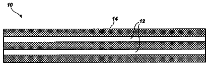
A rubber article reinforcing steel wire 10 of the present invention comprises a cross section in a width direction including a major diameter and a minor diameter, and the major diameter and the minor diameter are substantially perpendicular to each other. FIG. 1 illustrates an example of the cross-sectional shape of the rubber article reinforcing steel wire of the present invention. In the illustrated example, the cross section in the width direction has a track shape including a pair of parallel linear portions 11 and a pair of circular arc portions 12 that are convex outward and face each other. In this case, the major diameter means the width of the wire 10 while the minor diameter means the thickness of the wire 10 .
In the wire 10 of the present invention, assuming that the major diameter is W, the minor diameter is T, a straight line that passes through the center of the major diameter in a width direction and is parallel to a minor diameter direction (thickness direction) is L1, a straight line that passes through the center of the minor diameter in a width direction and is parallel to a major diameter direction (width direction) is L2, an intersection point of L1 and L2 is a center point C, a region within a half of a distance from the center point C to a surface of the wire 10 is a central region Rc (region surrounded by a dotted line in the drawing), and a region outside the central region Rc is a surface layer region Rs, the Vickers hardness Hvc of the central region Rc is more than the Vickers hardness Hvs of the surface layer region Rs.
When tension or bending force is applied to a rubber article in the state of embedding the wire 10 in rubber, similar tension or bending force is also applied to the internal wire 10 . In this case, the central region Rc of the wire 10 is near the neutral axis of bending deformation and is therefore resistant to the influence of the bending force. Thus, in the wire 10 of the present invention, the Vickers hardness Hvc of the central region Re of the wire 10 is allowed to be higher than the Vickers hardness Hvs of the surface layer region Rs, to secure the tensile strength of the wire 10 . In contrast, because the surface layer region Rs of the wire 10 is greatly undergoes tensile compressive force due to bending deformation, the Vickers hardness Hvs of the surface layer region Rs is set to be lower than the Vickers hardness Hvc of the central region Rc, to impart the surface layer region Rs with material properties with high ductility and to inhibit the generation of a surface crack which is a cause of fatigue fracture.
In addition, in the wire 10 of the present invention, assuming that a Vickers hardness on L1 in the surface layer region Rs is Hv1, and a Vickers hardness on L2 in the surface layer region Rs is Hv2, relationships represented by Expressions
to
described below: Hvc−Hv 1≦150 (1); Hvc−Hv 2≦150
Hv 1/ Hvc× 100≧85.11 (3); and Hv 2/ Hvc× 100≧79.84
are satisfied. This is because when the differences between the Vickers hardness Hvc of the central region Rc of the wire 10 and the Vickers hardnesses Hv1 and Hv2 of the surface region Rs are too large, the occurrence of bending deformation in the wire 10 may result in the concentration of shear distortion on a position with a low Vickers hardness, leading to the deterioration of fatigue durability.
In the wire 10 of the present invention, assuming that a Vickers hardness at an optional point that is R1×T (0<R1<0.5) apart from the center point C in a minor diameter direction (thickness direction) is Hv3, and a Vickers hardness at an optional point that is R2×W (0<R2<0.5) apart from the center point C in a major diameter direction (width direction) is Hv4, relationships represented by Expressions
to
described below: 3.0≦ W/T≦ 7.0 (5); −167× R 1.sup.2−117× R 1+630≦ Hv 3≦−167× R 1.sup.2−417× R 1+950 (6); and −375× R 2.sup.2−175× R 2+630≦ Hv 4≦−500× R 2.sup.2−150× R 2+950
are preferably satisfied.
In the case of W/T of less than 3.0, the large thickness T of the wire 10 is required for obtaining necessary strength when the wire 10 of the present invention is used as a material for reinforcing a rubber article, so that an insufficient weight-reduction effect may be provided. In contrast, a high aspect ratio in which W/T is more than 7.0 may cause the wire 10 to crack during processing and is not preferable likewise.
In addition, when Hv3 is less than the above-described range in Expression (6), the durability of a rubber article in which the wire 10 of the present invention is embedded may be deteriorated. In contrast, when Hv3 exceeds the above-described range in Expression (6), there is a fear of cracking the wire 10 during the processing of the wire 10 . Furthermore, when Hv4 is less than the above-described range in Expression (7), the durability of the rubber article in which the wire 10 of the present invention is embedded may be deteriorated. In contrast, when Hv4 exceeds the above-described range in Expression (7), there is a fear of cracking the wire 10 during the processing of the wire 10 . FIG. 2 is a graph showing the upper and lower limits of Hv3 in Expression (6), and FIG. 3 is a graph showing the upper and lower limits of Hv4 in Expression (7).
In addition, in the wire 10 of the present invention, assuming that a Vickers hardness at the center point C is Hv0, and a Vickers hardness at a position that is 0.4 W apart from the center point C on L2 is Hv5, a relationship represented by Expression
described below: 150≧ Hv 0− Hv 5≧60 is preferably satisfied. By allowing the Vickers hardness Hv5 at the position that is near the surface layer of the wire 10 to be lower than the Vickers hardness Hv0 of the center C, the wire 10 can be imparted with high ductility, to thereby inhibit a crack which is a cause of fatigue fracture from being generated on the surface of the wire 10 .
Furthermore, in the wire 10 of the present invention, as for Vickers hardness on L1, the Vickers hardness Hv0 at the center point C is highest; and assuming that a Vickers hardness at a position that is 0.25 T apart from the center point C on L1 is Hv6, a Vickers hardness at a position that is 0.45 T apart from the center point C on L1 is Hv7, a Vickers hardness at a position that is 0.25 W apart from the center point C on L2 is Hv8, and a Vickers hardness at a position that is 0.45 W apart from the center point C on L2 is Hv9, relationships represented by Expressions
and
described below: 0.55×( Hv 0+ Hv 7)≧ Hv 6≧0.45×( Hv 0+ Hv 7) (9); and 0.55×( Hv 0+ Hv 9)≧ Hv 8≧0.45×( Hv 0+ Hv 9)
are preferably satisfied. The satisfaction of Expressions
and
allows the distribution of Vickers hardness Hv to be gentle. In other words, the unsatisfaction of Expressions
and
results in the inverted U-shaped distribution of Vickers hardness Hv with the center point C as an apex whereas the satisfaction of Expressions
and
results in the almost inverted V-shaped distribution of Vickers hardness Hv. Accordingly, the satisfaction of Expressions
and
results in the wire that is more resistant to bending fatigue.
Furthermore, in the wire 10 of the present invention, assuming that the Vickers hardness at the center point C is Hv0, a Vickers hardness at a position that is 0.3 T apart from the center point C on L1 is Hv10, and a Vickers hardness at a position that is 0.3 W apart from the center point C on L2 is Hv11, a relationship represented by Expression
described below: 105≧ Hv 11/ Hv 10×100≧94
is preferably satisfied.
In addition, in the wire 10 of the present invention, the Vickers hardness Hv0 at the center point C is preferably 630 to 950. This is because when the Vickers hardness Hv0 at the center point C exceeds the above-described range, there is a fear of deteriorating the ductility of the wire 10 , leading to the deterioration of fatigue durability. In addition, this is because when the Vickers hardness Hv0 at the center point C is less than the above-described range, the strength of the wire is decreased, so that insufficient strength may be provided for a material for reinforcing a rubber article.
The rubber article reinforcing steel wire of the present invention has been explained in detail above, but it is essential only that the wire 10 of the present invention comprises a cross section in a width direction including a major diameter and a minor diameter, the major diameter and the minor diameter being substantially perpendicular to each other, wherein assuming that the major diameter is W, the minor diameter is T, a straight line that passes through the center of the major diameter in a width direction and is parallel to a minor diameter direction is L1, a straight line that passes through the center of the minor diameter in a width direction and is parallel to a major diameter direction is L2, an intersection point of L1 and L2 is a center point C, a region within a half of a distance from the center point C to a surface is a central region Rc, and a region outside the central region Rc is a surface layer region Rs, the Vickers hardness Hvc of the central region Rc is more than the Vickers hardness Hvs of the surface layer region Rs; and the wire 10 is not particularly additionally limited.
The cross-sectional shape of the wire of the present invention has been explained above using the wire 10 having a track shape including a pair of parallel linear portions 11 and a pair of circular arc portions 12 that are convex outward and face each other, but the cross-sectional shape of the wire of the present invention is not limited thereto. For example, FIG. 4 illustrates another example of the cross-sectional shape of the rubber article reinforcing steel wire of the present invention, and, as illustrated in the drawing, a wire 20 may have a generally rectangular shape including two pairs of parallel linear portions 21 a and 21 b as well as four circular arc portions 22 that connect the linear portions and are convex outward. In addition, FIG. 5 illustrates still another example of the cross-sectional shape of the rubber article reinforcing steel wire of the present invention, and, as illustrated in the drawing, a wire 30 may have an oval shape including a pair of circular arc portions 32 a that are convex outward as well as circular arc portions 32 b that have a less radius of curvature than that of the circular arcs and are convex outward.
In addition, the material or the like of the wire of the present invention is not particularly limited, any material can be used if being used conventionally, and a high carbon steel with 0.80 mass % or more of carbon component is preferable. Use of the high carbon steel with 0.80 mass % or more of carbon component, which has high hardness, as the material of the wire enables the effects of the present invention to be favorably obtained. In contrast, more than 1.5 mass % of carbon component is not preferred because of resulting in deteriorated ductility and in poor fatigue resistance.
The wire of the present invention can be manufactured by utilizing a conventional facility and step for manufacturing a normal wire having a circular cross section without being changed. Specifically, it can be economically and easily manufactured, e.g., by rolling it between rollers in the latter part of wire drawing or by passing it through the die of a flat hole, to allow it to be flat. In this case, it is essential only to appropriately set the conditions of the wire drawing and rolling of the wire so that the physical properties of the finally obtained wire satisfy the above-described requirements. For example, the rolling is performed by cold rolling processing using plural rolling stands including a pair of rolls of 120 mm or less in diameter. In this case, a rolling reduction at each pass in the cold rolling is set at 15% or less, a rolling reduction at each pass is set at not less than (rolling reduction at previous pass—1.0%), and back tension that is 3 to 20% of steel wire rupture strength is applied before processing at each pass.
A rubber article of the present invention will be explained below.
In the rubber article of the present invention, the above-described rubber article reinforcing steel wire of the present invention is embedded as a reinforcing material in rubber. Examples of the rubber article of the present invention include tires, industrial belts, and the like, and are particularly tires. When the rubber article of the present invention is applied to a tire or an industrial belt, the major diameter of the wire is preferably uniformalized in parallel with the in-plane direction of the tire or the industrial belt. As a result, the rubber article can be allowed to have a reduced thickness, to be excellent in view of weight reduction. For example, when the wires 10 , 20 , and 30 are used in a belt for reinforcing a tire, it is essential only to arrange the wires 10 , 20 , and 30 to have width directions uniformalized with respect to the in-plane direction of the belt. Because the wires 10 , 20 , and 30 of the present invention are excellent in fatigue durability, the fatigue durability of the obtained tire can also be improved.
Examples
The present invention will be explained in more detail below with reference to examples. Examples 1 to 12 and Comparative Examples 1 to 6
Rubber article reinforcing steel wires having cross-sectional shapes and Vickers hardness distributions listed in Tables 1 to 3 below were produced. A three-point bending fatigue test of each of the obtained wire was conducted to evaluate the fatigue properties of the wires. In addition, Hvc in Tables is a Vickers hardness Hv0 at a center point C, Hv1, Hv3, or Hv10 is a Vickers hardness at a position that is 0.3×T (R1=0.3) apart from the center point C of each wire in a minor diameter direction, and Hv2, Hv4, or Hv5 is Vickers hardness at a position that is 0.4×W (R2=0.4) apart from the center point C of each wire in a major diameter direction. In this case, the range of Expression
is from 580 to 810, and the range of Expression
is from 500 to 810. In addition, a Vickers hardness testing machine HM-11 manufactured by Mitutoyo Corporation was used for measuring Vickers hardness.
(Three-Point Bending Fatigue Test)
The number of times of application of repeated bending force in the state of applying a tensile load to each wire until a fracture occurred was measured. In the tables, such obtained values are listed together as indices based on 100 in Comparative Example 1. The higher value shows superior fatigue resistance.
TABLE-US-00001 TABLE 1 Comparative Example Example Example Example Example Example 1 1 2 3 4 5 Cross-Sectional Shape of Wire Track Track Rectangular Track Oval Track shape shape shape shape shape shape Corresponding Drawing FIG. 1 FIG. 1 FIG. 4 FIG. 1 FIG. 5 FIG. 1 Wire Diameter (mm) Thickness T 0.20 0.19 0.21 0.21 0.20 0.30 Width W 1.20 0.65 0.85 0.90 1.35 0.92 Width/Thickness Ratio W/T 6.0 3.4 4.0 4.3 6.8 3.1 Vickers Hvc (Hv0) 810 940 810 930 800 730 Hardness Thickness Hv1 (Hv3, Hv10) 705 800 710 805 705 670 (HV) Direction Hv6 — — — — — — Hv7 — — — — — — Hv0 − Hv1 105 140 100 125 95 60 0.55 × (Hv0 + Hv7) — — — — — — 0.45 × (Hv0 + Hv7) — — — — — — Width Hv2 (Hv4, Hv5) 640 805 700 790 660 675 Direction Hv8 — — — — — — Hv9 — — — — — — Hv11 685 840 728 830 696 692 Hv0 − Hv5 170 135 110 140 140 55 0.55 × (Hv0 + Hv9) — — — — — — 0.45 × (Hv0 + Hv9) — — — — — — Vickers Hv1/Hvc × 100 87.04 85.11 87.65 86.56 88.13 91.78 Hardness Hv5/Hvc × 100 79.01 85.64 86.42 84.95 82.50 92.47 Ratio Hv11/Hv10 × 100 97.16 105.00 102.54 103.11 98.72 103.28 Three-Point Bending Fatigue Test (Index) 100 106 125 120 124 109
TABLE-US-00002 TABLE 2 Example Example Comparative Comparative Comparative Comparative 6 7 Example 2 Example 3 Example 4 Example 5 Cross-Sectional Shape of Wire Rectangular Track Oval Rectangular Track Rectangular shape shape shape shape shape shape Corresponding Drawing FIG. 4 FIG. 1 FIG. 5 FIG. 4 FIG. 1 FIG. 4 Wire Diameter (mm) Thickness T 0.32 0.32 0.19 0.21 0.31 0.32 Width W 1.40 1.45 0.72 0.86 1.50 1.40 Width/Thickness Ratio W/T 4.4 4.5 3.8 4.1 4.8 4.4 Vickers Hvc (Hv0) 645 720 940 960 750 705 Hardness Thickness Hv1 (Hv3, Hv10) 590 630 780 790 615 610 (HV) Direction Hv6 — — — — — — Hv7 — — — — — — Hv0 − Hv1 55 90 160 170 135 95 0.55 × (Hv0 + Hv7) — — — — — — 0.45 × (Hv0 + Hv7) — — — — — — Width Hv2 (Hv4, Hv5) 515 600 770 780 585 530 Direction Hv8 — — — — — — Hv9 — — — — — — Hv11 556 635 815 828 633 580 Hv0 − Hv5 130 120 170 180 165 175 0.55 × (Hv0 + Hv9) — — — — — — 0.45 × (Hv0 + Hv9) — — — — — — Vickers Hv1/Hvc × 100 91.47 87.50 82.98 82.29 82.00 86.52 Hardness Hv5/Hvc × 100 79.84 83.33 81.91 81.25 78.00 75.18 Ratio Hv11/Hv10 × 100 94.24 100.79 104.49 104.81 102.93 95.08 Three-Point Bending Fatigue Test (Index) 132 119 91 82 87 99
TABLE-US-00003 TABLE 3 Comparative Example Example Example Example Example Example 6 8 9 10 11 12 Cross-Sectional Shape of Wire Track Track Track Oval Rectangular Track shape shape shape shape shape shape Corresponding Drawing FIG. 1 FIG. 1 FIG. 1 FIG. 5 FIG. 4 FIG. 1 Wire Diameter (mm) Thickness T 0.32 0.29 0.21 0.20 0.21 0.19 Width W 1.45 0.95 0.90 1.35 0.85 0.65 Width/Thickness Ratio W/T 4.5 3.3 4.3 6.8 4.0 3.4 Vickers Hvc (Hv0) 745 740 945 760 810 940 Hardness Thickness Hv1 (Hv3, Hv10) 585 690 805 695 710 800 (HV) Direction Hv6 — — — — 728 825 Hv7 — — — — 655 580 Hv0 − Hv1 160 50 140 65 100 140 0.55 × (Hv0 + Hv7) — — — — 806 836 0.45 × (Hv0 + Hv7) — — — — 659 684 Width Hv2 (Hv4, Hv5) 605 685 805 613 700 805 Direction Hv8 — — — — 745 870 Hv9 — — — — 680 635 Hv11 640 700 853 652 728 840 Hv0 − Hv5 140 55 140 147 110 135 0.55 × (Hv0 + Hv9) — — — — 820 866 0.45 × (Hv0 + Hv9) — — — — 671 709 Vickers Hv1/Hvc × 100 78.52 93.24 85.19 91.45 87.65 85.11 Hardness Hv5/Hvc × 100 81.21 92.57 85.19 80.66 86.42 85.64 Ratio Hv11/Hv10 × 100 109.40 101.45 105.96 93.81 102.54 105.00 Three-Point Bending Fatigue Test (Index) 88 105 104 107 125 106
Tables 1 to 3 described above reveals that the wire of the present invention is excellent in bending fatigue properties.
Description of symbols
10 , 20 , 30 Rubber article reinforcing wire 11 , 21 Linear portion 12 , 22 , 32 Circular arc portion
 Lapsed, fee not paid1 drawing