Background of the disclosure
1. Field of disclosure
The present disclosure relates to a hazardous material containment bag system. More particularly, the present disclosure relates to a hazardous material containment bag system having a multi-layered structure or bags that form a matrix of structural layers and active agent(s) to minimize contamination when handling or transporting human remains or hazardous materials exposed to a chemical, biological, radiological, and/or toxicological agent.
2. Description of the related art
Safe containment for the handling and transporting of hazardous materials, such as contaminated forensic material and equipment and, particularly, human remains continues to be a problem. Those handling such contaminated material run the risk of being exposed to the contamination and, as a result, of themselves being contaminated.
Conventional bags for the handling and transporting of contaminated material or of human remains generally comprise a tough, impermeable, preferably air- and fluid-tight, outer material. If the outer material is torn, punctured or otherwise compromised, the containment ability of conventional bags for the handling and transporting of contaminated material is lost in whole or in part.
Conventional bags for the handling and transporting of contaminated material or human remains provide only non-specific protection against contamination by a chemical, biological, radiological, and/or toxicological agent. By “non-specific” is meant protection that is not designed or directed to containing the specific contamination that is present. As a result, those handling and/or transporting such contaminated material or human remains run the risk of exposure and usually wear auxiliary protection. Such auxiliary protection has shortcomings, such as being cumbersome, preventing effective communication between those handling and/or transporting the contaminated material or human remains, and being not completely effective unless appropriately selected for the particular contamination faced. In this latter regard, often the precise nature of the contamination is not immediately known, so that the selection of the containment for the contaminated material or human remains, and/or the protection for those handling and transporting contaminated materials or human remains, involves a level of guesswork.
Therefore, a need exists for a bag or bag system for the handling and transporting of contaminated material, such as chemicals, biological materials, radiological materials, and/or toxicological agents, or human remains that can provide secure containment of the contaminating agent that is the source of such contaminated material or human remains.
A need also exists for a bag or bag system for the handling and transporting of contaminated material or human remains that can provide safe and effective protection for those handling and transporting such contaminated material or human remains.
A need further exists for a bag or bag system for the handling and transporting of contaminated material or human remains for which the identity of the contaminating agent is not known.
In addition, a need exists for a bag or bag system for the handling and transporting of contaminated material or human remains that serves to maintain to a large degree its containment ability if the bag is torn, punctured or otherwise compromised.
Summary of the disclosure
The present disclosure provides a hazardous material containment bag or bag system for the handling and transporting of contaminated material, such as chemicals, biological materials, radiological materials, and/or toxicological agents, or human remains.
The present disclosure also provides such a hazardous material containment bag that has a multi-layered structure or bags that form a matrix of structural layers and active agent(s) to minimize (as defined herein, to prevent or at least reduce) contamination by a chemical, biological, radiological and/or toxicological agent.
The present disclosure further provides a hazardous material containment bag that has a multi-layered structure that forms a matrix of structural layers and active agent(s) for handling and transporting of contaminated material or human remains that is a flexible, sealable container having an outer substrate that forms the overall structure of the hazardous material containment bag, and a closure that provides access to the inside of the hazardous material containment bag and, thus, opens and closes the bag, and an absorbent body inside the hazardous material containment bag.
The present disclosure yet further provides a hazardous material containment bag that has a multi-layered structure that forms a matrix of structural layers and active agent(s), in which an active agent is present in any of its structural layers that is selected to neutralize or minimize contamination by a contaminant that is a chemical, biological, radiological and/or toxicological agent, to provide flexibility and adaptability to handle the challenge of the contaminant.
The present disclosure still further provides that a hazardous material containment bag that has a multi-layered structure that forms a matrix of structural layers and active agent(s) that can be made of a material and/or chemical agent in its structure that interacts with odor-causing chemical compounds from the human remains, embalming chemicals, or contaminated material inside the hazardous material containment bag, to prevent or at least reduce migration of the odor-causing chemical compounds into the ambient environment by the absorption or adsorption of gases or odors including volatile chemicals.
The present disclosure also provides that a multi-layer hazardous material containment bag that has a multi-layered structure that forms a matrix of structural layers and active agent(s) can optionally incorporate nanotechnology, such as nanoparticles, in any of its structural layers to increase the safety of handling, containment, and transportation of material, human remains, or hazardous materials.
The present disclosure further provides for one of the layers in the multi-layered structure being an absorbent material, which will help immobilize hazardous liquid, bodily fluids, and/or gases emanating from the hazardous contaminants or human remains.
The present disclosure further provides for a second embodiment which is a bag system having an inner bag and a separate outer bag with the inner bag being a multi-layered structure having an absorbent material, which will help immobilize hazardous liquid, bodily fluids, and/or gases emanating from the hazardous contaminants or human remains.
As mentioned above, the present disclosure relates to a hazardous material containment bag or bag system. More particularly, the present disclosure relates, in one embodiment, to a hazardous material containment bag for transporting human remains, or a deceased animal body (e.g., a horse or dog), or a hazardous material that has been contaminated by a chemical, biological, radiological, and/or toxicological agent.
Brief description of the drawings
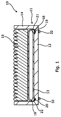
FIG. 1 shows a top plan view of an embodiment of a hazardous material containment bag of the present disclosure.
FIG. 2 shows a top plan view of another embodiment of a hazardous material containment bag of the present disclosure.
FIG. 3 shows a bottom view of the hazardous material containment bag of the embodiments of FIG. 1 or 2 .
FIG. 4 shows a perspective top view of the hazardous material containment bag in FIG. 2 with a recloseable flap open.
FIG. 5 is a perspective view of a portion of another embodiment of the present disclosure.
FIG. 6A shows a sectional, perspective view of the embodiment of FIG. 5 .
FIG. 6B shows an end perspective view of the embodiment of FIG. 5 .
FIG. 6C is an exploded area 6 C of FIG. 6A .
FIG. 7 shows a top, schematic of the embodiment of FIG. 5 .
FIG. 8 is an exploded schematic view that illustrates an active agent positioned between layers of material in an embodiment of the hazardous material containment bag.
FIG. 9 shows a partially exploded view of an embodiment of a hazardous material containment bag of the present disclosure having a plurality of individual layers.
FIG. 10 shows a partially exploded view of another embodiment of a hazardous material containment bag of the present disclosure having a plurality of individual layers.
FIG. 11 shows an exploded sectional view of reinforced gripping devices of the embodiment of the hazardous material containment bag in FIG. 2 .
FIG. 12 shows a perspective view of the embodiment of the hazardous material containment bag with a decedent's body therein of FIG. 2 .
FIG. 13 is a cross-sectional view of a second embodiment, namely a modular hazardous remains system, of the present disclosure taken along line 13 - 13 of FIG. 19 .
FIG. 14 is a perspective view of a biological inner bag of the system of FIG. 13 .
FIG. 15( a ) is a cross-sectional view of the biological containment inner bag of FIG. 14 taken along line 15 - 15 of FIG. 14 .
FIG. 15( b ) is a detailed view of a portion of the inner biological containment bag of FIG. 15( a ) .
FIG. 16 is a perspective view of a chemical inner bag of the system of FIG. 13 .
FIG. 17( a ) is a cross-sectional view of the chemical containment inner bag of the system of FIG. 13 taken along line 17 - 17 of FIG. 16 .
FIG. 17( b ) is a detailed view of a portion of the inner chemical containment bag of FIG. 17( a ) .
FIG. 17( c ) is a cross-sectional view of anther embodiment of the inner chemical containment bag of FIG. 17( a ) .
FIG. 17( d ) is a detailed view of a portion of the inner chemical containment bag of FIG. 17( c ) .
FIG. 18 is a cross-sectional view of the inner bag of the system of FIG. 13 .
FIG. 19 is a cross-sectional view of the system of FIG. 13 .
FIG. 20 is a perspective view of the system of FIG. 13 .
Detailed description of the disclosure
Referring now to the drawings and, in particular, to FIG. 1 , there is shown a first exemplary embodiment of a hazardous material containment bag of the present disclosure generally represented by reference numeral 10 . The overall aesthetic appearance of hazardous material containment bag 10 is analogous to the lightweight absorbent body bag disclosed in pending U.S. patent application Ser. No. 12/741,331, now published as U.S. Patent Application Publication No. 2010/0263178A1, which application is incorporated by reference. However, hazardous material containment bag 10 of the present disclosure has a multi-layered structure. This structure forms a matrix of structural layers and active agent(s) to minimize (as defined herein means prevent or at least reduce) contamination by a chemical, biological, radiological and/or toxicological agent.
As used in this application, “minimize” (or “minimizing”) contamination means prevent (or substantially prevent) or at least reduce contamination by a chemical, biological, radiological and/or toxicological agent.
To “reduce” contamination means to decrease contamination by at least 50% as compared with a conventional bag; and more preferably, means to decrease contamination by at least 60%, 70%, 75%, 80%, 85%, 90%, 95%, or 99%, and all increments therein, and optimally 100%. Clearly, the larger percentage decrease in contamination is the most preferred.
The matrix of structural layers and active agent(s) of hazardous material containment bag 10 can be selected to provide optimal effectiveness, flexibility and adaptability to minimize contamination by a chemical, biological, radiological and/or toxicological agent.
In one embodiment, hazardous material containment bag 10 has a matrix of structural layers and an active agent that form a “base” structure that minimizes contamination by a known range of chemical, biological, radiological and/or toxicological hazards, and which can also be used even when the chemical, biological, radiological and/or toxicological hazard has not yet been identified.
In another embodiment, hazardous material containment bag 10 has a matrix of structural layers and an active agent that are selected to form a “targeted” structure that minimizes contamination by a particular range of chemical, biological, radiological and/or toxicological agents that have been identified.
For example, the structural layers of materials in hazardous material containment bag 10 can be selected as to the number of layers, the material used for each layer, the thickness of each layer, the spacing between adjacent layers, and one or more coatings or treatments (e.g., urethane coating, surfactant) on or in each layer.
Similarly, hazardous material containment bag 10 can have one or more active agents that are a chemical compound present in and/or on any layer to interact with and minimize contamination by a chemical, biological, radiological and/or toxicological agent. For example, a structural layer that forms an interior surface of cover 80 and/or backing substrate 12 can have an active agent that is a chemical compound that chemically reacts with and neutralizes a toxic and/or noxious gas exuded by human remains or a hazardous material enclosed in hazardous material containment bag 10 .
In another embodiment, hazardous material containment bag 10 also has a chemical compound that is a surface active agent for odor control. Any layer can also have another active agent that is a chemical compound that interacts with an odor-causing agent exuded from human remains, embalming chemical, or hazardous material to chemically neutralize the odorous compound, or that adsorbs or absorbs the odorous compound. In this embodiment, hazardous material containment bag 10 also has one or more structural layers that form a physical barrier to penetration by an odorous compound, where the one or more structural layers are, for example, the backing substrate, absorbent body, cover, and/or the sublayers that form one or more of these structures. For example, a structural layer that is part of cover 80 and or backing substrate 12 can have a chemical compound that is a highly porous material that attracts, adsorbs and traps volatile organic compounds on its surface (such as, but not limited to, activated carbon), and thereby minimizes the amount of volatile organic compounds penetrating cover 80 and/or backing substrate 12 . In this embodiment, the matrix of active agent and structural layers prevents or at least reduces the odorous compound from penetrating hazardous material containment bag 10 , where the odorous compounds would otherwise contaminate the bearers and the nearby environment.
Referring to FIGS. 1 to 4 , hazardous material containment bag 10 has a cover 80 . Cover 80 includes a closure 90 . Hazardous material containment bag 10 preferably has one or more gripping devices 25 along one side of hazardous material containment bag 10 , and corresponding gripping devices 25 along the opposite side of hazardous material containment bag 10 . Gripping devices 25 are provided with a reinforcement piece 35 to strengthen gripping devices 25 for use. Cover 80 includes a recloseable flap 140 that can be opened to provide access to the interior of hazardous material containment bag 10 for contaminated material or human remains to be placed therein. FIGS. 1 and 2 each illustrate a different reclosable flap 140 . Further, recloseable flap 140 is in the closed position in each of FIGS. 1 and 2 .
A binder 18 can be connected to one or more edges at the perimeter of hazardous material containment bag 10 . Binder 18 provides a defined edge to and reinforces the integrity and shape of hazardous material containment bag 10 when in use. Binder 18 can be made of a webbing material, such as polyester or polypropylene, or nylon or a nylon-based material. Binder 18 can be connected to hazardous material containment bag 10 with thread, adhesive, VELCRO®, or can be thermally attached. Binder 18 can be attached onto the edge of hazardous material containment bag 10 to a width of between about one-quarter (¼) inch and about 2 inches, with a preferred width of about 1.25 inches along a long edge of hazardous material containment bag 10 . Hazardous material containment bag 10 also has a thermal seal 130 around the perimeter of the hazardous material containment bag 10 , thereby forming a compartment 135 having a continuous seal to make compartment 135 partially or, preferably, completely water- and fluid-resistant or impervious. Hazardous material containment bag 10 can also have one or more pockets 145 for storing documents.
Hazardous material containment bag 10 can also have one or more gussets (not shown), or gusset areas, that provide extra material for expansion of containment bag 10 to address if the contaminated item or decedent's body are large. Each gusset is preferably located at a corner of containment bag 10 . More preferably, containment bag 10 has a gusset at each of the four corners. In another embodiment, each gusset can have from about one
inch or larger seal at the seal point, and more preferably has a six
inch seal at the seal point, in all four corners of containment bag 10 .
Cover 80 has a first side (not shown) and a second side 82 . First side faces the bottom side of hazardous material containment bag 10 , and second side 82 is a top (outside or exposed) side of cover 80 . The second (top) side 82 of cover 80 is shown in FIGS. 1 and 2 . Cover 80 is positioned on the top of hazardous material containment bag 10 and is connected to backing substrate 12 , as shown in FIG. 3 .
Cover 80 in conjunction with backing substrate 12 is intended to enclose contaminated material or human remains placed inside hazardous material containment bag 10 , and also provide system integrity for the entire hazardous material containment bag 10 . Cover 80 can be one or more pieces of material shaped and sized to join together on top of hazardous material containment bag 10 to form a tent-like interior in hazardous material containment bag 10 in which contaminated material or human remains can be placed to be completely enclosed and from which the contaminant is prevented or inhibited from escaping to the outside of the containment bag. Cover 80 is preferably made of one or more materials that exhibit weather resistance, water resistance, fatigue resistance, chemical resistance, and/or resistance to puncture or tearing. Cover 80 can be connected to backing substrate 12 at an outer edge of hazardous material containment bag 10 , by an adhesive material or by forming a thermal seal 130 between cover 80 and backing substrate 12 or by sewing. In one embodiment of hazardous material containment bag 10 , cover 80 and backing substrate 12 are connected under binder material 18 to provide hazardous material containment bag 10 with complete integrity and a finished appearance.
Cover 80 can be chosen preferably based on the hazardous material containment bag 10 . Backing substrate 12 is always impervious, however again dependent on the purpose of the hazardous material containment bag 10 , cover 80 can use a number of different materials. Thus, cover 80 can be a material including, but not limited to, nylon, polymer (such as polypropylene or polyethylene), plastic, polyester, polyester blend, cloth (such as canvas, hemp, flax, or cotton fiber), or combinations of these materials. In one embodiment, cover 80 is made of nylon, including treated nylon. In yet another embodiment, cover 80 is made of polyethylene or polypropylene. In an alternative embodiment, cover 80 is made of cotton or canvas, including treated canvas.
Thermal bonding can be used to form a continuous thermal seal 130 around the periphery of hazardous material containment bag 10 , to form compartment 135 in hazardous material containment bag 10 that is self-contained and water-resistant/fluid-resistant. A preferred technique for thermal bonding is Radio Frequency (RF) welding technology. Alternatively, ultrasonic bonding or heat bonding techniques can create thermal seal 130 . Thermal bonding can be achieved by melting a thermal bonding agent that is applied to backing substrate 12 and cover 80 , creating a seam for a thermal bond that is between about one-quarter (¼) inch to about one
inch, and preferably about one-half (½) inch to about three-quarter (¾) inch, in a continuous segment around hazardous material containment bag 10 to form compartment 135 . In an alternative embodiment, the thermal bonding uses a coating that is applied to a portion of backing substrate 12 and to cover 80 to create the thermal seal 130 including, but not limited to, a urethane coating.
Referring to FIG. 3 , hazardous material containment bag 10 has a backing substrate 12 that forms a part of, or the entire, back surface of the hazardous material containment bag. Backing substrate 12 has a first side and a second side. The first side faces the top side of hazardous material containment bag 10 , and the second side is a bottom (outside or exposed) side of the backing substrate 12 . Backing substrate 12 provides support, ruggedness and strength to hazardous material containment bag 10 .
Referring to FIG. 4 , hazardous material containment bag 10 is shown with cover 80 having recloseable flap 140 in an open position, exposing first side of cover 80 and absorbent body 14 in an interior of hazardous material containment bag 10 .
As shown in FIG. 1 , closure 90 can run in a straight course from the top end to the bottom end of containment bag 10 . More specifically, closure 90 can be a zipper that runs in a straight course, is about 103 inches in length, and stops about 2.5 inches from each of the top end and the bottom end of containment bag 10 . A straight run of closure 90 preserves the teeth track of the zipper, and also avoids any leakage of the contents of containment bag 10 . Alternatively, as shown in FIGS. 2 to 4 , closure 90 can have an envelope-style (“D-shape”) configuration in an unfastened condition, where one part of closure 90 is along the edge of recloseable flap 140 and the other part of closure 90 remains on cover 80 .
Hazardous material containment bag 10 can have a pocket 145 located on any outer surface. As shown in FIG. 4 , pocket 145 is in dotted lines to illustrate its location on the side of recloseable flap 140 that faces the exterior of hazardous material containment bag 10 . Pocket 145 can be used to hold documents or personal items relating to the contaminated material or human remains. In one embodiment, pocket 145 is positioned on the outer surface of cover 80 , again so that the information placed inside pocket 145 would be accessible without exposure to the hazardous material or remains inside containment bag 10 .
FIG. 4 also shows hazardous material containment bag 10 with gripping devices 25 and a reinforcement piece 35 for each gripping device 25 , as well as thermal seal 130 . Binder 18 can be positioned and connected along a long edge of hazardous material containment bag 10 to overlay a small portion of absorbent body 14 and backing substrate 12 .
Backing substrate 12 can be partially or completely impermeable to fluids such as water, blood, body fluids, or chemicals associated with embalming or preserving a decedent's body, and serves as a fluid barrier to prevent (or at least reduce) fluids exuded by the body from contaminating the area beneath and around hazardous material containment bag 10 or the bearers who are carrying the bag. Fluid impermeability of backing substrate 12 also reduces effects of outside water (from the ground or from rain and snow) from seeping into hazardous material containment bag 10 , where such water could compromise the integrity of hazardous material containment bag 10 or a decedent's body therein. Backing substrate 12 can be a material that is naturally fluid-impermeable or a material that has been chemically treated to reduce liquid permeability (e.g., treated nylon or treated cloth), or a material that is coated to reduce liquid permeability, such as by urethane or a polyester. Backing substrate 12 is also preferably made of a material that resists tears or punctures, to provide ruggedness to hazardous material containment bag 10 . Backing substrate 12 can also have a low-slip or non-slip surface so that hazardous material containment bag 10 stays in position when placed on a surface.
Absorbent body 14 is preferably connected to the first (top) side of backing substrate 12 . Absorbent body 14 is typically sized less than backing substrate 12 so that a portion of the backing substrate forms an edge about a portion of absorbent body 14 . Absorbent body 14 can be permanently connected to backing substrate 12 , or can be removably connected (as a separate piece) to backing substrate 12 . In an alternative embodiment (not shown), a portion of absorbent body 14 , or another, separate absorbent body 14 , can also be affixed to or cover the first side of cover 80 , including the side of recloseable flap 140 that faces the interior of hazardous material containment bag 10 .
An embodiment of hazardous material containment bag 10 has absorbent body 14 that is removably connected to backing substrate 12 , so that the absorbent body can be replaced with a new, or different absorbent body on the same backing substrate 12 . This permits the user to easily replace an absorbent body 14 having structural layers and/or chemical compounds that are selected to interact with a particular type of chemical, biological, radiological or toxicological contaminant with a different absorbent body (not shown) having structural layers and/or chemical compounds that interact with or trap a different type of chemical, biological, radiological or toxicological contaminant. Removability also permits a used absorbent body 14 to be removed after use from hazardous material containment bag 10 , and replaced with a new, unused absorbent body 14 . Before new absorbent body 14 could be inserted, containment bag 10 would need to be decontaminated using proper procedures and recertified as clean. Absorbent body 14 can be removably connected to backing substrate 12 (and/or to cover 80 ) by an adhesive material, where the adhesive material includes, but is not limited to, glue, tape, two-sided tape, thread, and/or a hook-and-loop interlocking device such as VELCRO® (Velcro Industries B.V. LLC Netherlands, Curacao, Netherlands Antilles).
In another embodiment, absorbent body 14 is positioned on all, or substantially all, of the inner surfaces of hazardous material containment bag 10 , including first (inner) side of cover 80 and backing substrate 12 , such that the absorbent body 14 encases the contents of hazardous material containment bag 10 .
As shown in FIGS. 1 to 4 , hazardous material containment bag 10 includes a backing substrate 12 and an absorbent body 14 connected to a first side of backing substrate 12 and/or connected to a first side of cover 80 . In some embodiments, absorbent body 14 can also cover part or all of closure 90 when recloseable flap 140 is in the closed position. Hazardous material containment bag 10 completely encloses and encases the contaminated material or human remains placed therein when recloseable flap 140 of cover 80 is closed with closure 90 .
Referring to FIGS. 5-7 , this embodiment of hazardous material containment bag 100 has two structures, namely an inner liner or shell 110 that encloses part or all of contaminated human remains or hazardous material and an outer shell 120 to enclose inner shell 110 , as shown clearly in FIGS. 6A and 6B , to form a bag-inside-a-bag hazardous material containment bag 100 . This hazardous material containment bag 100 isolates contaminants inside the inner liner 110 from escaping outside of hazardous material containment bag 100 . The inner liner 110 can have an active agent that can absorb, adsorb, neutralize, deactivate, and/or destroy chemical, biological, radiological and/or toxicological agents. For this hazardous material containment bag 100 embodiment, outer shell 120 opens wide to allow inner shell 110 , perhaps a bag, to remain physically placed therein. Inner shell 110 can be attached to outer shell 120 at welded area 160 as shown in FIG. 6C or can be unattached to outer shell 120 and simply placed therein (not shown). This hazardous material containment bag 100 embodiment offers an added benefit of one hermetical closure inside of another thereby making it harder for contaminants to escape.
Outer shell 120 of hazardous material containment bag 100 can be gas and/or vapor permeable or impervious to the passage of gas and/or vapor. Preferably, outer shell 120 is impervious to the passage of gas and/or vapor. Also preferably, all seams 122 of outer shell 120 are sealed to provide an additional degree of gas and/or vapor impervious nature to the bag for handling and transporting contaminated material or human remains. Inner shell 110 can be made of the same or different material as outer shell 120 . However, it is important that the properties of outer shell 120 be directed to provide strength to hazardous material containment bag 100 , and that the properties of inner shell 110 be directed to prevent or greatly reduce chemical, biological and other contaminants from escaping out of the hazardous material containment bag 100 .
Outer shell 120 has a closure 125 . Closure 125 provides access to the inside volume of hazardous material containment bag 100 , namely inner shell 110 , and should be of sufficient dimension to permit relatively simple, rapid and easy placement of the contaminated material or human remains therein. Preferably, closure 125 is a zipper having complementary male and female teeth 126 , 128 . Further, closure 125 is airtight and watertight. To ensure that closure 125 is watertight, closure 125 has a coating and/or is sealed with a liquid-resistant sealer, such as nickel silver elements. Closure 125 can also be tamper-evident and/or tamper-resistant. Closure 125 can be a size 10 zipper marketed under the trade name “YKK Proseal”, which meets the full requirements of SOLAS Chapter 3.32.3, 46 CFR 106.171-17, NFPA 1991, 1992, 1994 Class 2, ASTM F1052 and ASTM1359. YKK Proseal is rated at approximately 0.2-0.5 bar water pressure. Closure 125 can include a wide tape having a first tape section 127 attached to teeth 126 and a second tape section 129 attached to teeth 128 . The first and second tape sections 127 , 129 are each made of a polyester woven fiber having polyurethane laminated to the polyester fiber. Closure 125 can slightly arc across hazardous material containment bag 100 .
Inner shell 110 has a closure 115 . Preferably, closure 115 is also a zipper having complementary male and female teeth 116 , 118 . Also, as with closure 125 , closure 115 is airtight. However, closure 115 is also waterproof. To ensure that closure 115 is waterproof, closure 115 can have a coating and/or be sealed with a waterproof sealer. Closure 115 extends in a straight line across hazardous material containment bag 100 to preserve the teeth 116 , 118 of closure 115 and avoid any leakage of the contents of hazardous material containment bag 100 . Closure 115 can also be tamper-evident and/or tamper-resistant.
In this hazardous material containment bag 100 embodiment, closure 125 is laterally offset from closure 115 to ensure that closures 125 and 115 do not obstruct one another. Closure 125 is also longer than closure 115 , preferably by about two to four inches, so that closure 115 and inner shell 110 are readily accessible when closure 125 is opened. Closure 115 can be a size 10 zipper marketed under the trade name “YKK Aquaseal”, which meets the full requirements of ISO 12402-7, NFPS 1992, 1994 Class 2, ASTM F1359. YKK Aquaseal is rated at approximately 0.3 bar water pressure. Closure 115 can include a wide tape having a first tape section 117 attached to teeth 116 and a second tape section 119 attached to teeth 118 . The first and second tape sections 117 , 119 have a base that can be made of polyester woven fiber impregnated with polyurethane.
Referring to all embodiments, absorbent body 14 is made of an absorbent or superabsorbent material, and can absorb a large quantity of liquid, such as blood or other body fluids, or embalming chemicals, that are exuded from a decedent's body or by contaminated material in hazardous material containment bag 10 . Examples of absorbent and superabsorbent materials that can be used for absorbent body 14 include, but are not limited to, cellulose, cellulose fiber, airlaid, airlaid nonwoven, airlaid composite, fluff pulp, bonding fiber, superabsorbent polymer (SAP), SAP composite, compressed composite containing a portion of short or microfiber material, thermoplastic polymer fiber, thermoplastic polymer granule, cellulose powder, cellulose gel, airlaid with SAP, fibrous or foam structure coated or impregnated with SAP, starch-based absorbents or starch-based superabsorbents, such as BioSAP™ (Archer Daniels Midland, Decatur, Ill.), and any combinations thereof. In one embodiment, absorbent body 14 is made of one or more layers of tissue. In another embodiment, absorbent body 14 has a top layer that is a low-slip or non-slip material, or treated with a non-slip agent, to reduce movement or slipping of a decedent's body. In another embodiment, absorbent body 14 has a top surface or top layer that is made of polyethylene and/or polypropylene, or that is made of non-woven material.
Absorbent body 14 can include one or more layers of absorbent or superabsorbent material. The one or more layers of absorbent material can be a top layer, a bottom layer, and/or a middle layer. Each layer of absorbent body 14 can be positioned adjacent to another layer without being adhered to the next layer, or some (or all) of layers in the absorbent body can be bonded together into a composite structure. The one or more layers of absorbent body 14 can be bonded with an adhesive material, or by using static attraction and/or corona discharge techniques.
Any layer of absorbent material in absorbent body 14 can be treated or coated with a surfactant to regulate uptake and strikethough of liquids, or to direct absorption to another portion or zone of absorbent body 14 . Examples of surfactants that can be used in the present disclosure include anionic, cationic, zwitterionic, and non-ionic surfactants.
For ease of disposability, absorbent body 14 is made in one embodiment of a biodegradable and/or compostable absorbent material, such as the starch-based absorbent or starch-based superabsorbent material noted above, including, but not limited to, BioSAP™ (Archer-Daniels Midland, Decatur, Ill.).
Absorbent body 14 is typically sized somewhat smaller than the overall outer dimensions (also called “footprint”) of hazardous material containment bag 10 and backing substrate 12 . Some exemplary sizes of absorbent body 14 in relation to the overall outer dimensions of hazardous material containment bag 10 are as follows:
TABLE-US-00001 Hazardous Material Containment Bag Absorbent body outer dimensions outer dimensions (width × length) (width × length) Portion* 20″ × 25″ 18″ × 23″ Portion/Infant 20″ × 36″ 18″ × 34″ Adolescent 30″ × 55″ 28″ × 53″ Standard 33″ × 78″ 31″ × 76″ Extra Large (XL) 36″ × 91″ 34″ × 89″ *“Portion” is a portion of a human body or other animal body.
Absorbent body 14 also can be shaped to fit easily inside hazardous material containment bag 10 . In one embodiment, absorbent body has one or more cut-outs along the lengthwise sides of hazardous material containment bag 10 to prevent the absorbent body from overlapping and covering gripping devices 25 .
Absorbent body 14 can have one or more strengthening layers (not shown) to improve the strength and/or resistance to tearing of the absorbent body. The one or more strengthening layers can be located on top of, below, or in between any portion of absorbent body 14 . A strengthening layer can be made of standard non-woven material, or meltblown or spunlace composites. In one embodiment, the strengthening layer is a polypropylene non-woven or polypropylene/meltblown non-woven material.
As noted above, absorbent body 14 can absorb a large quantity of fluids. In one embodiment, absorbent body 14 , with the use of high SAP levels, can absorb up to 7 liters of fluids, such as water or blood and other bodily fluids. In another embodiment, absorbent body 14 and a second absorbent body having the same structure of absorbent body 14 and located on the inside surface of the top of hazardous material containment bag 10 can absorb up to 6.7 liters, which is about 6,500 grams to about 6,850 grams of water, blood, or other fluids. Total absorbency of fluids is a function, in part, of the overall size and type of absorbent material employed in absorbent body 14 . A typical absorbent material used in absorbent body 14 has about one-and-three-quarters (1.75) grams of absorbency per square inch of absorbent material. However, absorbency can be adjusted to a higher or lower level by changing to another, higher-performance absorbent, such as a superabsorbent.
FIG. 8 illustrates an embodiment of the present disclosure in which an active agent 50 is disposed or dispersed between two absorbent layers 46 , 48 that form a portion of the absorbent body. In this embodiment, cover stock 52 covers the top surface of absorbent layer 46 . A backing substrate 44 is below absorbent layer 48 . Other embodiments can have one or more active agents disposed in or on more than two layers of absorbent body 14 .
FIG. 9 illustrates an embodiment of a layer-by-layer structure of the multi-layered structure of hazardous material containment bag 10 having four structural layers. Moving from right-to-left in the direction from the exterior toward the interior of hazardous material containment bag 10 , outer layer 76 forms the outer surface of backing substrate 12 , and thus also forms a part of or the entire back surface of hazardous material containment bag 10 . Moving inward, the next layer is an absorbent layer 77 that forms a portion of absorbent body 14 , and which is adjacent to outer layer 76 . Continuing inward, the next layer is another absorbent layer 78 that also forms a portion of absorbent body 14 . Alternatively, layer 78 can be a protective layer. Further inward is an inner layer 79 that is adjacent to absorbent layer 78 and thus adjacent to absorbent body 14 which will be the nearest layer of the multi-layered structure to any human remains that are placed in hazardous material containment bag 10 .
In an embodiment of the plurality of structural layers in FIG. 9 , outer layer 76 is made of nylon backing material that can optionally have a urethane coating, absorbent layers 77 and 78 are made of one or more of the absorbent or superabsorbent materials provided above for absorbent body 14 , and inner layer 79 is made of a nylon backing material with a urethane coating or similar coating layer.
In an embodiment of hazardous material containment bag 10 , one or more of layers 76 , 77 , 78 and 79 is a laminate structure having two or more layers bonded to each other to form a laminate layer with increased strength, durability, thickness, uniformity, and/or barrier characteristics. Specifically, a laminate layer can have two, three, four, five, six, or seven layers, and preferably two to four layers, of the same material or of different materials that are bonded together. The number of layers can be larger in those laminates in which microlayers are used.
The description continues in the full USPTO document.
 Lapsed, fee not paid5 drawings