Cross-reference to related application
This application claims priority under 35 U.S.C. §119 from Japanese Patent Application No. 2015-251133 filed on Dec. 24, 2015. The entire subject matter of the application is incorporated herein by reference.
Background
Technical Field
The following description relates to aspects of a printer, a method, and a non-transitory computer-readable storage medium for printing images on a long print medium while conveying the print medium.
Related Art
A printer (hereinafter referred to as a “first-type printer”) has been known that is configured to invalidate a particular sheet when a printing operation could not completely been performed up to an intended line on the particular sheet because of an electric power outage or an error caused during the printing operation. Further, a printer (hereinafter referred to as a “second-type printer”) has been known that is configured to sequentially print a plurality of pages on a long print medium while conveying the print medium. In the second-type printer, it is possible to produce a label of each page by cutting the print medium, on which the plurality of pages have been sequentially printed, on a page-by-page basis.
Summary
In the known first-type printer, the particular sheet on which the printing operation could not completely been performed up to the intended line is invalidated as a whole, and therefore might be discarded as waste. Further, in the known second-type printer, suppose for instance that when a second page has been continuously printed after a first page was printed, an error (e.g., an electric power outage) occurs before the print medium is cut in a boundary between the first page and the second page. In such a case, when the printer recovers from the error and resumes the printing operation, the printer prints the second page again from the beginning without cutting the print medium in the boundary between the first page and the second page. Hence, a user has to cut the print medium by user's own hands to produce a label of the first page.
Aspects of the present disclosure are advantageous to provide one or more improved techniques, for a printer, which make it possible to appropriately cut a print medium with images printed thereon even though an error is caused while printing is being performed on the print medium.
According to aspects of the present disclosure, a printer is provided, which includes a conveyor configured to convey a print medium in a conveyance direction along a conveyance path, a print head configured to sequentially print a plurality of page images on the print medium in a first position on the conveyance path, each page image being an image representing a single unit of page, a cutter configured to cut the print medium in a second position on the conveyance path, the second position being downstream of the first position in the conveyance direction, a first storage configured to store print data for printing each of the plurality of page images, a second storage configured to store a cut target position of the print medium to be cut by the cutter, and a controller configured to execute a printed matter producing process including controlling the print head to sequentially print the plurality of page images on the print medium based on the print data stored in the first storage, while controlling the conveyor to convey the print medium, storing into the second storage a cut target position for each of the page images printed on the print medium, and when the cut target position stored in the second storage reaches the second position, controlling the cutter to cut the print medium, an interrupting process including interrupting the printed matter producing process when an error occurs during the execution of the printed matter producing process, and storing an uncut position of the print medium into a particular storage, the uncut position being a cut target position located between the first position and the second position when the printed matter producing process is interrupted, and a first resuming process including resuming the printed matter producing process when the error is settled during the interruption of the printed matter producing process, and controlling the cutter to cut the print medium when the uncut position stored in the interrupting process reaches the second position.
According to aspects of the present disclosure, further provided is a method adapted to be implemented on a processor coupled with a printer including a conveyor, a print head, a cutter, a first storage, and a second storage. The method includes a printed matter producing process including controlling the print head to sequentially print a plurality of page images on the print medium in a first position on a conveyance path based on print data stored in the first storage while controlling the conveyor to convey a print medium in a conveyance direction along the conveyance path, storing into the second storage a cut target position for each of the page images printed on the print medium, the cut target position being a position of the print medium to be cut by the cutter, and controlling the cutter to cut the print medium in the second position when the cut target position stored in the second storage reaches a second position on the conveyance path, the second position being downstream of the first position in the conveyance direction, an interrupting process including interrupting the printed matter producing process when an error occurs during the execution of the printed matter producing process, and storing an uncut position of the print medium into a particular storage, the uncut position being a cut target position located between the first position and the second position when the printed matter producing process is interrupted, and a resuming process including resuming the printed matter producing process when the error is settled during the interruption of the printed matter producing process, and controlling the cutter to cut the print medium when the uncut position stored in the interrupting process reaches the second position.
According to aspects of the present disclosure, further provided is a non-transitory computer-readable medium storing computer-readable instructions that are executable by a processor coupled with a printer including a conveyor, a print head, a cutter, a first storage, and a second storage. The instructions are configured to, when executed by the processor, cause the processor to execute a printed matter producing process including controlling the print head to sequentially print a plurality of page images on the print medium in a first position on a conveyance path based on print data stored in the first storage while controlling the conveyor to convey a print medium in a conveyance direction along the conveyance path, storing into the second storage a cut target position for each of the page images printed on the print medium, the cut target position being a position of the print medium to be cut by the cutter, and controlling the cutter to cut the print medium in the second position when the cut target position stored in the second storage reaches a second position on the conveyance path, the second position being downstream of the first position in the conveyance direction, an interrupting process including interrupting the printed matter producing process, and storing an uncut position of the print medium into a particular storage when an error occurs during the execution of the printed matter producing process, the uncut position being a cut target position located between the first position and the second position when the printed matter producing process is interrupted, and a resuming process including resuming the printed matter producing process when the error is settled during the interruption of the printed matter producing process, and controlling the cutter to cut the print medium when the uncut position stored in the interrupting process reaches the second position.
Brief description of the accompanying drawings
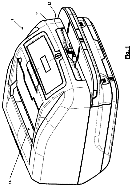
FIG. 1 is a perspective view showing a printer when viewed from an upper front left side, in an illustrative embodiment according to one or more aspects of the present disclosure.
FIG. 2 is a perspective view showing a main body casing of the printer when viewed from an upper front side, in the illustrative embodiment according to one or more aspects of the present disclosure.
FIG. 3 is a plain view schematically showing an internal configuration of the printer in the illustrative embodiment according to one or more aspects of the present disclosure.
FIG. 4 is a block diagram showing an electrical configuration of the printer in the illustrative embodiment according to one or more aspects of the present disclosure.
FIGS. 5 and 6 are flowcharts showing a procedure of a main process to be executed by the printer in the illustrative embodiment according to one or more aspects of the present disclosure.
FIG. 7 exemplifies a correction table in the illustrative embodiment according to one or more aspects of the present disclosure.
FIGS. 8A, 8B, and 8C are illustrations showing a flow of a printed matter producing process in the illustrative embodiment according to one or more aspects of the present disclosure.
FIGS. 9A, 9B, and 9C are illustrations showing a flow of the printed matter producing process in the illustrative embodiment according to one or more aspects of the present disclosure.
FIGS. 10A, 10B, 10C, and 10D are illustrations showing a flow of the printed matter producing process in the illustrative embodiment according to one or more aspects of the present disclosure.
FIGS. 11A and 11B are illustrations showing a flow of the printed matter producing process in the illustrative embodiment according to one or more aspects of the present disclosure.
FIGS. 12A, 12B, and 12C are illustrations showing a flow of the printed matter producing process in the illustrative embodiment according to one or more aspects of the present disclosure.
FIGS. 13A, 13B, and 13C are illustrations showing a flow of the printed matter producing process in the illustrative embodiment according to one or more aspects of the present disclosure.
Detailed description
It is noted that various connections are set forth between elements in the following description. It is noted that these connections in general and, unless specified otherwise, may be direct or indirect and that this specification is not intended to be limiting in this respect. Aspects of the present disclosure may be implemented on circuits (such as application specific integrated circuits) or in computer software as programs storable on computer-readable media including but not limited to RAMs, ROMs, flash memories, EEPROMs, CD-media, DVD-media, temporary storage, hard disk drives, floppy drives, permanent storage, and the like.
Hereinafter, an illustrative embodiment according to aspects of the present disclosure will be described with reference to the accompanying drawings. In the following description, an upside, a downside, a left side, a right side, a front side, and a rear side of a printer 1 of the illustrative embodiment will be defined as shown in FIG. 1 .
As shown in FIG. 1 , the printer 1 includes two printing mechanisms, and is configured to perform printing on a tape 8 and a tube 9 with the two printing mechanisms, respectively. The tape 8 is a strip-shaped print medium. The tube 9 is a tubular print medium. The printer 1 includes a housing 10 . The housing 10 includes a main body casing 11 and a cover 12 . The main body casing 11 is formed in the shape of a rectangular parallelepiped box having a longitudinal direction along a left-to-right direction. The cover 12 is a plate-shaped member disposed above the main body casing 11 . A rear end portion of the cover 12 is rotatably supported by an upper rear end portion of the main body casing 11 . When the cover 12 is closed relative to the main body casing 11 (see FIG. 1 ), the cover 12 covers an attachment surface 11 A (see FIG. 2 ). When the cover 12 is open relative to the main body casing 11 , the attachment surface 11 A is exposed upward (see FIG. 2 ).
At side surfaces of the housing 10 , a tape outlet 14 , a tube inlet 15 , a tube outlet 16 , and a user interface 17 are disposed. The tape outlet 14 is disposed at a front surface of the housing 10 . The tape outlet 14 is an opening for discharging the tape 8 out of the housing 10 therethrough. The tube inlet 15 is disposed at a right surface of the housing 10 . The tube inlet 15 is an opening for introducing the tube 9 into the housing 10 therethrough. The tube outlet 16 is disposed at a left surface of the housing 10 . The tube outlet 16 is an opening for discharging the tube 9 out of the housing 10 therethrough. The user interface 17 includes a display and operable members. The display includes a plurality of LEDs configured to show an operating condition of the printer 1 . The operable members include a plurality of operable buttons such as a power button and a start button.
As shown in FIG. 2 , at the attachment surface 11 A, a tape attachment section 20 , a ribbon attachment section 30 , and a tube attachment section 40 are disposed. The tape attachment section 20 is a recessed section having an open upper side. The tape attachment section 20 is configured such that a tape cassette 80 is detachably attached thereto. In the illustrative embodiment, the tape attachment section 20 is positioned at a right portion of the attachment surface 11 A. When the cover 12 is open (see FIG. 1 ), a user is allowed to detachably attach the tape cassette 80 to the tape attachment section 20 from above. A conveyance guide 23 is a groove that continuously extends frontward from a front right portion of the tape attachment section 20 . A front end portion of the conveyance guide 23 is connected with the tape outlet 14 .
The ribbon attachment section 30 is a recessed section having an open upper side. The ribbon attachment section 30 is configured such that a ribbon cassette 90 is detachably attached thereto. In the illustrative embodiment, the ribbon attachment section 30 is positioned at a left portion of the attachment surface 11 A. When the cover 12 is open, the user is allowed to detachably attach the ribbon cassette 90 to the ribbon attachment section 30 from above. The tube attachment section 40 is configured such that the tube 9 (see FIG. 1 ) is detachably attached thereto.
The tube attachment section 40 is an upward-open groove extending from the tube inlet 15 to the tube outlet 16 . In the illustrative embodiment, the tube attachment section 40 passes behind the tape attachment section 20 and the ribbon attachment section 30 . Further, the tube attachment section 40 communicates with a rear end portion of the ribbon attachment section 30 . When the cover 12 is open, the user is allowed to detachably attach the tube 9 to the tube attachment section 40 from above. The tube 9 is attached to the tube attachment section 40 , so as to extend from the tube inlet 15 to the tube outlet 16 .
As shown in FIG. 3 , the tape cassette 80 is formed in a box shape and configured to accommodate the unused tape 8 , an unused ink ribbon (not shown), a tape driving roller 81 , and a ribbon winding spool 82 . The tape driving roller 81 is configured to pull the tape 8 out of the tape cassette 80 . The ribbon winding spool 82 is configured to wind the ink ribbon in the tape cassette 80 .
The tape attachment section 20 includes a print head 51 , a tape driving shaft 55 , and a ribbon winding shaft 56 . The print head 51 is a thermal head configured to perform line-by-line printing using a plurality of printing elements arranged in a direction perpendicular to a conveyance direction of the tape 8 . The tape driving shaft 55 is configured to rotate the tape driving roller 81 . The ribbon winding shaft 56 is configured to rotate the ribbon winding spool 82 . On the right of the tape attachment section 20 , a platen holder 52 is disposed. The platen holder 52 is configured to rotatably support a platen roller 53 and a movable conveyance roller 54 . The platen roller 53 is opposed to the print head 51 and rotatable relative to the print head 51 . The movable conveyance roller 54 is opposed to the tape driving shaft 55 and rotatable relative to the tape driving shaft 55 .
When the cover 12 (see FIG. 1 ) is opened, the platen holder 52 moves to a retreat position such that the platen roller 53 and the movable conveyance roller 54 are placed outside the tape attachment section 20 . When the user attaches the tape cassette 80 to the tape attachment section 20 , the tape driving shaft 55 and the ribbon winding shaft 56 are inserted into the tape driving roller 81 and the ribbon winding spool 82 , respectively.
Subsequently, when the cover 12 is closed, the platen holder 52 moves to an operating position such that the platen roller 53 and the movable conveyance roller 54 are placed inside the tape attachment section 20 . At this time, the platen roller 53 urges, toward the print head 51 , the tape 8 and the ink ribbon of the tape cassette 80 in an overlapped manner. The movable conveyance roller 54 pinches the tape 8 and the ink ribbon of the tape cassette 80 with the tape driving roller 81 . Thereby, the printer 1 is placed in a printable state where the printer 1 is allowed to perform printing on the tape 8 of the tape cassette 80 .
Behind the tape outlet 14 (i.e., on a rear side of the tape outlet 14 ), a cutter 57 is disposed. The cutter 57 is configured to cut the tape 8 laid in the conveyance guide 23 in a thickness direction of the tape 8 . More specifically, the cutter 57 is capable of half cutting to cut a part (e.g., only a release paper) of layers of the tape 8 thereby forming a slit, and is capable of full cutting to cut off all (e.g., the release paper and a mount) of the layers of the tape 8 .
The ribbon cassette 90 is formed in a box shape and configured to accommodate an unused ink ribbon and a ribbon winding spool 91 . The ribbon attachment section 30 includes a print head 61 , a movable conveyance roller 62 , and a ribbon winding shaft 63 . The print head 61 is a thermal head configured to perform line-by-line printing by a plurality of printing elements arranged in a direction perpendicular to a conveyance direction of the tube 9 . The movable conveyance roller 62 is opposed to the print head 61 and rotatable relative to the print head 61 . The ribbon winding shaft 63 is configured to rotate the ribbon winding spool 91 .
When the cover 12 (see FIG. 1 ) is opened, the movable conveyance roller 62 is placed behind the tube attachment section 40 and separated away from the print head 61 . When the user attaches the ribbon cassette 90 to the ribbon attachment section 30 , the ribbon winding shaft 63 is inserted into the ribbon winding spool 91 . The user attaches the tube 9 to the tube attachment section 40 . Subsequently, when the cover 12 is closed, the movable conveyance roller 62 is placed inside the tube attachment section 40 and positioned close to the print head 61 . At this time, the movable conveyance roller 62 urges, toward the print head 61 , the tube 9 attached to the tube attachment section 40 and the ink ribbon of the ribbon cassette 90 in an overlapped manner. Thereby, the printer 1 is placed into a state where the printer 1 is allowed to perform printing on the tube 9 with the ribbon cassette 90 .
On the right of the tube outlet 16 , a cutter 64 is disposed. The cutter 64 is configured to cut the tube 9 attached to the tube attachment section 40 in a radial direction of the tube 9 . The cutter 64 is capable of half cutting to cut a part of the tube 9 in the radial direction thereby forming a slit, and is capable of full cutting to completely cut off the tube 9 in the radial direction.
Referring to FIG. 4 , an electrical configuration of the printer 1 will be described. The printer 1 includes a control board 19 . The control board 19 includes a CPU 41 , a ROM 42 , a CGROM 43 , a RAM 44 , a flash memory 45 , and an input/output interface (hereinafter, which may be referred to as an I/O I/F) 49 interconnected via a data bus. The ROM 42 stores programs 42 a to be executed by the CPU 41 to take control of the printer 1 . The CGROM 43 stores print dot pattern data for printing characters. The characters include at least one of letters, letter strings, numerals, symbols, figures, and illustrations. The RAM 44 is configured to temporarily store data. The RAM 44 includes a receive buffer 44 A configured to temporarily store print data received from an external device. The flash memory 45 is configured to store characters acquired from an external device, and store a below-mentioned correction table 100 (see FIG. 7 ).
The I/O I/F 49 is connected with an operation interface 17 , a built-in battery 18 , drive circuits 71 , 72 , 73 , 74 , 75 , and 76 , and an external connection I/F 77 . When the printer 1 is connected with an external power supply (not shown), the built-in battery 18 is supplied with electricity from the external power supply and is charged. When the printer 1 is not connected with the external power supply, the built-in battery 18 supplies electric power charged therein to the printer 1 .
The drive circuit 71 includes an electronic circuit configured to drive the print head 51 . The drive circuit 72 includes an electronic circuit configured to drive a conveyance motor 88 for rotating the tape driving shaft 55 and the ribbon winding shaft 56 . The drive circuit 73 includes an electronic circuit configured to drive the cut motor 89 for operating the cutter 57 . The drive circuit 74 includes an electronic circuit configured to drive the print head 61 . The drive circuit 75 includes an electronic circuit configured to drive a conveyance motor 98 for rotating the movable conveyance roller 62 and the ribbon winding shaft 63 . The drive circuit 76 includes an electronic circuit configured to drive a cut motor 99 for operating the cutter 64 .
The external connection I/F 77 is an interface for connecting an external device with the printer 1 . In the illustrative embodiment, a PC 2 , as an external device, is connected with the printer 1 via the external connection I/F 77 . In the PC 2 , an editor is installed that is an application program for the user to edit page images. Each page image represents print contents, including at least one character, for a single unit of page. The user edits page images with the editor on the PC 2 , and thereafter issues an instruction to print the page images. In the illustrative embodiment, each page image includes an image area 101 in which one or more characters are printed, and a margin area 102 provided around the image area 101 (see FIGS. 11A and 11B ).
In this case, a CPU (not shown) of the PC 2 transmits to the printer 1 a print command for instructing the printer 1 to print the edited page images. In the illustrative embodiment, the print command indicates which print medium (the tape 8 or the tube 9 ) the page images are to be printed on, the number of pages to be printed, and print information for each page image. The print information for each page image indicates the number of print lines for the page image and cut settings (e.g., a cutting type and a cut target position). The cutting type indicates one of full cutting and half cutting. The cut target position indicates a position to be cut of the tape 8 with the page image printed thereon.
In the illustrative embodiment, when a page image is a normal page image, the printer 1 is allowed to produce a label 8 A (see FIG. 9A ) on the entire surface of which the page image is printed. The normal page image is a page image having a page length equal to or more than a lower limit (e.g., 10 mm). It is noted that the page length is a length of a page in the conveyance direction. The cut target positions for a normal page image corresponding to the top page (i.e., the first page) are a head line and a bottom line (i.e., both ends in the conveyance direction) of the page image. The cut target position for a normal page image corresponding to each of the following pages (i.e., the second and subsequent pages) is a bottom line of the page image.
In the illustrative embodiment, when a page image is a special page image, the printer 1 is allowed to produce a special label 8 C (see FIG. 12C ). The special page image is a page image having a page length less than the lower limit. The special label 8 C is such a label that a page image is printed on a page section 103 . The page section 103 has a length equal to the lower limit in the conveyance direction, and is a downstream portion of the special label 8 C in the conveyance direction. The special label 8 C is half-cut in a boundary position (i.e., a bottom line of the page image) between the page section 103 and a margin section 104 . The margin section 104 is positioned upstream of the page section 103 in the conveyance direction.
Accordingly, the cut target positions for a special page image corresponding to the top page are a head line, a bottom line, and a margin-added line of the special page image. The margin-added line is positioned a distance of the lower limit upstream of the head line of the page image in the conveyance direction. In this case, the cutting type to be applied for the head line and the margin-added line is “full cutting.” Meanwhile, the cutting type to be applied for the bottom line is “half cutting.”
Further, the CPU of the PC 2 sequentially generates line-by-line print data based on the edited page images, and sequentially transmits the generated print data to the printer 1 . Each piece of the line-by-line print data causes the printer 1 to print, as a print unit, a single line of the page images to be printed by the print head 51 or the print head 61 . Thereby, a plurality of pieces of print data, required for printing all of the page images to be printed, are sequentially transmitted from the PC 2 to the printer 1 . When there exist a plurality of page images to be printed, a plurality of pieces of print data, each of which represents a corresponding page image, are transmitted in accordance with a sequence in which the plurality of page images are to be printed.
In the printer 1 , the received print command and the received print data are stored into the receive buffer 44 A. The CPU 41 reads the print command and the print data out of the receive buffer 44 A in the stored order. When reading out the print command from the receive buffer 44 A, the CPU 41 begins to perform a below-mentioned printed matter producing process. When reading out print data from the receive buffer 44 A, the CPU 41 converts the print data into image data of a single line, based on the print dot pattern data stored in the CGROM 43 . Then, the CPU 41 stores the image data generated through the conversion, into an image buffer (not shown) of the RAM 44 . The CPU 41 executes the following printed matter producing process while sequentially reading out image data stored in the image buffer.
When reading out a print command regarding the tape 8 , the CPU 41 starts the printed matter producing process on the tape 8 . As shown in FIG. 3 , the conveyance motor 88 rotates the tape driving shaft 55 and the ribbon winding shaft 56 thereby rotating the tape driving roller 81 and the ribbon winding spool 82 . Along with rotation of the tape driving roller 81 , an unused tape 8 is pulled out of the tape cassette 80 . Along with rotation of the ribbon winding spool 82 , an unused ink ribbon is pulled out of the tape cassette 80 . The pulled-out tape 8 and the pulled-out ink ribbon 86 are fed between the print head 51 and the platen roller 53 .
The print head 51 prints characters on the tape 8 with the ink ribbon, based on the image data sequentially read out from the image buffer, in synchronization with conveyance of the tape 8 . The used ink ribbon is wound by the ribbon winding spool 82 . The printed tape 8 is conveyed into the conveyance guide 23 by the movable conveyance roller 54 and the tape driving roller 81 . Further, the printed tape 8 is cut by the cutter 57 on a page-image-by-page-image basis, and discharged from the tape outlet 14 .
When reading out a print command regarding the tube 9 , the CPU 41 starts a printed matter producing process on the tube 9 . As shown in FIG. 3 , the conveyance motor 98 rotates the movable conveyance roller 62 to convey the tube 9 in the tube attachment section 40 , and rotates the ribbon winding shaft 63 to rotate the ribbon winding spool 91 . Along with rotation of the ribbon winding spool 91 , an unused ink ribbon is pulled out of the ribbon cassette 90 . The pulled-out ink ribbon is fed between the print head 61 and the movable conveyance roller 62 .
The print head 61 prints characters on the tube 9 with the ink ribbon, based on the image data sequentially read out from the image buffer, in synchronization with conveyance of the tube 9 . The used ink ribbon is wound by the ribbon winding spool 91 . The printed tube 9 is conveyed downstream of the print head 61 in the conveyance direction of the tube 9 , by the movable conveyance roller 62 . Further, the printed tube 9 is cut by the cutter 64 on a page-image-by-page-image basis, and discharged from the tube outlet 16 .
Referring to FIGS. 5 to 13C , a main process for the printed matter producing process will be described. FIGS. 8A to 8C schematically show a positional relationship among the tape 8 , the print head 51 , and the cutter 57 in the printed matter producing process for the sake of easy understanding (the same applies to FIGS. 9A to 13C ). When reading out the print command from the receive buffer 44 A, the CPU 41 launches the main process by loading and executing one or more programs 42 a stored in the ROM 42 .
In the following description, a printed matter producing process to be performed on the tape 8 based on the main process will be exemplified. It is noted, in this regard, that the same may apply to a printed matter producing process to be performed on the tube 9 based on the main process. As shown in FIGS. 8A to 8C , a position where the tape 8 is cut in a width direction thereof by the cutter 57 is referred to as a “cutter position T 2 .” A position where a single line of character is printed on the tape 8 by the print head 51 is referred to as a “head position T 1 .” The cutter position T 2 is located downstream of the head position T 1 in the conveyance direction of the tape 8 .
As shown in FIG. 5 , firstly, the CPU 41 performs a pre-printing process (S 1 ). Specifically, the CPU 41 stores the number of pages to be printed and the print information of each page image into a particular area of the RAM 44 based on the print command read out from the receive buffer 44 A. In the particular area of the RAM 44 , the CPU 41 sets the print information of the page image corresponding to the top page, as a processing target. The CPU 41 sets the cut target position for the page image corresponding to the top page, in a cut-setting area of the RAM 44 . The CPU 41 initializes a current conveyance position (unit: dots) stored in the RAM 44 to “zero.”
Afterward, the CPU 41 begins to convey the tape 8 by driving the conveyance motor 88 (S 3 ). Then, the CPU 41 performs print control for the current conveyance position (S 5 ). Specifically, the CPU 41 reads out image data for printing a line corresponding to the current conveyance position on the tape 8 , from the image buffer of the RAM 44 , based on the print information of the processing target set in the RAM 44 . The CPU 41 controls the print head 51 to print a single line based on the read image data.
Subsequently, the CPU 41 determines whether an error is occurring (S 7 ). When determining that an error is not occurring (S 7 : No), the CPU 41 determines whether the head position T 1 is in a page end position, based on the current conveyance position stored in the RAM 44 (S 9 ). Specifically, when the head position T 1 is not coincident with the bottom line of a page image being printed (i.e., an upstream end of the page image being printed in the conveyance direction) in the conveyance direction, the CPU 41 determines that the head position T 1 is not in the page end position (S 9 : No).
In this case, the CPU 41 determines whether the cutter position T 2 is in a cut target position (S 11 ). Specifically, when the cutter position T 2 is not coincident with the cut target position set in the cut-setting area of the RAM 44 in the conveyance direction, the CPU 41 determines that the cutter position T 2 is not in the cut target position (S 11 : No). In this case, the CPU 41 increments the current conveyance position stored in the RAM 44 by one (S 13 ), and then goes back to S 1 .
When determining that an error is occurring (S 7 : Yes), the CPU 41 determines whether the error is a specific error (S 15 ). The specific error may be an error that could be settled by simple user operations. Examples of the specific error may include an error caused due to an electric power shortage of the printer 1 and an error caused when the cover 12 is improperly opened. The electric power shortage of the printer 1 is a state where an electric power supplied to the printer 1 is reduced to less than a reference value from equal to or more than the reference value. For instance, the electric power shortage of the printer 1 might be caused due to a power failure of an external power supply connected with the printer 1 , breaking of a power cable connected with the printer 1 , or a reduction in electric power charged in the built-in battery 18 . It is noted that even though the electric power shortage of the printer 1 occurs, the electric power remaining in the built-in battery 18 is supplied to the control board 19 , and therefore various kinds of data stored in the RAM 44 are safely saved.
When determining that the error is a specific error (S 15 : Yes), the CPU 41 interrupts the printed matter producing process by stopping conveyance of the tape 8 and printing on the tape 8 , and stores print interruption information into the RAM 44 (S 17 ). In the illustrative embodiment, the print interruption information includes print information of a print-interrupted page, print information of uncut pages, and a conveyance speed just before interruption. The print-interrupted page is a page image only a part of which is printed because of the interruption of the printed matter producing process. The uncut pages are normal page images of which the bottom lines are not cut or special page images of which the margin-added lines are not cut, among page images positioned downstream of the head position T 1 at the time when the printed matter producing process is interrupted. Each of the print information of the print-interrupted page and the print information of the uncut pages includes an uncut position. The uncut position is a cut target position located between the head position T 1 and the cutter position T 2 at the time of the interruption of the printed matter producing process. The conveyance speed just before interruption is a conveyance speed of the tape 8 immediately before the interruption of the printed matter producing process.
When determining that the error is not a specific error (S 15 : No), the CPU 41 determines that the error is a non-specific error. For instance, the non-specific error may be an error that could not be settled by simple user operations. Examples of the non-specific error may include an error caused due to malfunction of the printer 1 and an error caused when the tape cassette 80 needs to be replaced. In this case, the CPU 41 interrupts the printed matter producing process, and terminates the main process after performing a process required depending on a type of the error.
When the head position T 1 is coincident in the conveyance direction with the bottom line of the page image being printed, the CPU 41 determines that the head position T 1 is in the page end position (S 9 : Yes). In this case, the CPU 41 determines whether the printed page image corresponds to a final page, based on the number of pages to be printed that is indicated by the print command (S 19 ). When determining that the printed page image does not correspond to the final page (S 19 : No), the CPU 41 sets next page print information as a processing target, based on the print command (S 21 ).
The next page print information is print information of a next page image to be printed (hereinafter, simply referred to as a “next page image”). In S 21 , the CPU 41 sets the bottom line of the next page image as a new cut target position in the cut-setting area of the RAM 44 . Further, the CPU 41 stores the cutting type for the newly-set cut target position into the cut-setting area. After S 21 , the CPU 41 goes to S 11 . When determining that the printed page image corresponds to the final page (S 19 : Yes), the CPU 41 further conveys the tape 8 , and controls the cutter 57 to full-cut (i.e., completely cut off) the bottom line of the final page in the cutter position T 2 . Thereafter, the CPU 41 terminates the main process.
When the cutter position T 2 is coincident in the conveyance direction with the cut target position set in the cut-setting area of the RAM 44 , the CPU 41 determines that the cutter position T 2 is in the cut target position (S 11 : Yes). In this case, the CPU 41 drives the cut motor 89 and performs cut control (S 23 ). Specifically, the CPU 41 controls the cutter 57 to perform half cutting or full cutting in accordance with the cutting type for the cut target position. Thereby, the cut target position of the tape 8 is cut in accordance with the cutting type.
In S 23 , when the bottom line of the page image is cut, a label 8 A (see FIGS. 9A to 9C ) of a single page unit is produced. The CPU 41 deletes, from the particular area of the RAM 44 , the print information and the print data of the page image corresponding to the produced label 8 A among the print information and the print data read out from the receive buffer 44 A. After S 23 , the CPU 41 goes to S 13 .
As shown in FIG. 6 , the CPU 41 determines whether the specific error has been settled (S 33 ). When determining that the specific error has not been settled (S 33 : No), the CPU 41 waits for a user operation for settling the specific error (S 35 ) and goes back to S 33 . For instance, when the specific error is an error caused due to electric power shortage of the printer 1 , the user may solve the power failure of the external power supply or restore the broken power cable as a user operation for settling the specific error. Thereby, as the amount of electricity supplied to the printer 1 is brought back to a level equal to or more than the reference value, the CPU 41 determines that the specific error has been settled (S 33 : Yes).
Thus, when the specific error has been settled, the CPU 41 executes a re-printing preparation for bringing the printer 1 back to an operable state in order to resume the printed matter producing process (S 37 ). At this time, the CPU 41 deletes the cut target position stored in the cut-setting area of the RAM 44 . The printer 1 of the illustrative embodiment is allowed to perform an arbitrarily-selected one of a plurality of previously-prepared resuming processes (e.g., below-mentioned first to third resuming processes) after executing the re-printing preparation. In the flash memory 45 , stored is a resuming process specified as a target process to be executed from among the plurality of resuming processes.
The description continues in the full USPTO document.
 Lapsed, fee not paid10 drawings