 Lapsed, fee not paid4 drawings
Cameras, Displays & Optics · US 9,843,837 B2
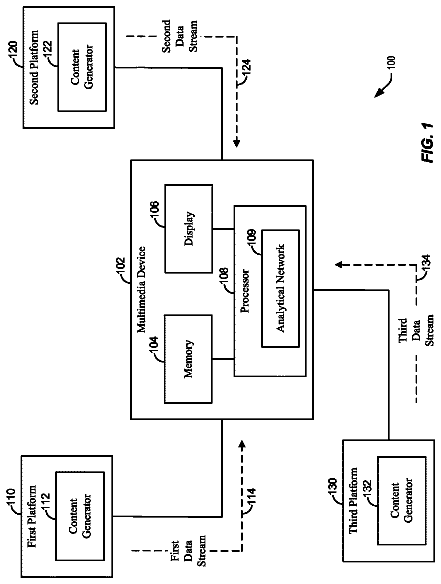
Cross-platform analysis
A method includes receiving, at a processor, a first data stream from a first platform and a second data stream from a second platform.
US 9,844,152 B2 · Assignee: LG ELECTRONICS INC. · Inventors: Heo; Jinha et al.
Sheet 1 of 43 from the published document. All sheets in the USPTO PDF
A display device includes a housing; at least one roller positioned within the housing; and a display portion including a display panel and a module cover, and the module cover is divided into a plurality of sections. The display panel and the module cover can transition from a first state where the display panel and the module cover are wound around the at least one roller to a second state where the display panel and the module cover are unwound from the at least one roller, in contact with each other, and exposed out of the housing.
Field of the Disclosure The present disclosure relates to a display device, and more particularly, to a display device with supports that are positioned between first and third module covers so that the supports are shielded from the outside, and allowing the user to immerse themselves into the display screen. Background With the development of the information society, demand for various displays is increasing. Responding to this demand, various displays such as LCDs (liquid crystal display devices), PDPs (plasma display panels), ELDs (electroluminescent displays), VFDs (vacuum fluorescent displays), etc., are being researched and used. Among these displays, those using organic light-emitting diodes (OLEDs) offer superior luminance and viewing angles compared to LCDs and can be made extremely thin because they work without a backlight.
1 of 43 drawing sheets so far from the published document, cropped to the drawing. Every sheet is in the USPTO PDF.
What the patent claimed, word for word. All of it is now free to use.
This application claims the benefit of Korean Patent Application No. 10-2015-0167365 filed on Nov. 27, 2015, and No. 10-2015-0185197 filed on Dec. 23, 2015, the entire contents of which are incorporated herein by reference for all purposes as if fully set forth herein.
Field of the Disclosure
The present disclosure relates to a display device, and more particularly, to a display device with supports that are positioned between first and third module covers so that the supports are shielded from the outside, and allowing the user to immerse themselves into the display screen.
Background
With the development of the information society, demand for various displays is increasing. Responding to this demand, various displays such as LCDs (liquid crystal display devices), PDPs (plasma display panels), ELDs (electroluminescent displays), VFDs (vacuum fluorescent displays), etc., are being researched and used.
Among these displays, those using organic light-emitting diodes (OLEDs) offer superior luminance and viewing angles compared to LCDs and can be made extremely thin because they work without a backlight.
One aspect is to provide a display device including a housing; at least one roller positioned within the housing; and a display portion including a display panel and a module cover, and the module cover is divided into a plurality of sections, wherein the display panel and the module cover can transition from a first state where the display panel and the module cover are wound around the at least one roller to a second state where the display panel and the module cover are unwound from the at least one roller, in contact with each other, and exposed out of the housing.
The module cover may include: a first module cover section positioned at a center portion of a back of the display panel in the second state; a third module cover section positioned at both side portions of the back of the display panel in the second state; a second module cover section positioned at a back of the first and third module cover sections in the second state; and a fourth module cover section positioned at top edge portions of the first and second module cover sections, with both side edge portions being connected to the third module cover section.
The display device may further include a motor assembly, a top bar attached to a top portion of the display portion, and a plurality of supports to raise or lower the top bar, one end of the supports being connected to either end of the top bar and the other end being connected to the motor assembly, wherein the top bar may be attached to the top edge of the first module cover section and the fourth module cover section.
The first and fourth module cover sections may be attached to the top bar through at least one hole, and the second module cover section may be attached to the first and third module cover sections through at least one hole.
The first and third module cover sections may be spaced apart from each other by a distance in a horizontal direction.
The display device may further include a motor assembly, a top bar attached to a top portion of the display portion, and a plurality of supports to raise or lower the top bar, one end of the supports being connected to either end of the top bar and the other end being connected to the motor assembly, wherein the supports may be positioned in the space between the first and third module covers.
The display device may further include a motor assembly, a top bar attached to a top portion of the display portion, and a plurality of supports to raise or lower the top bar, one end of the supports being connected to either end of the top bar and the other end being connected to the motor assembly, wherein the fourth module cover section, and flat regions of the first and third module cover sections, which are positioned in the uppermost part of the first and third module cover sections, may remain flat in the first state.
A front surface of the first and third module cover sections may vertically protrude from a front surface of the second module cover section.
The display device may further include a motor assembly, a top bar attached to a top portion of the display portion, and a plurality of supports to raise or lower the top bar, one end of the supports being connected to either end of the top bar and the other end being connected to the motor assembly, wherein each support may include: an upper link, one end of which is connected to either end of the top bar; a hinges connected to the other end of the upper link; and a lower link, one end of which is connected to the hinge and the other end is connected to the motor assembly.
The hinge may include: a body; and an attachment part protruding towards the first module cover section from the body, wherein the attachment part may include a magnetic material.
The second module cover section may include trajectories to correspond to areas where the attachment parts move during a transition from the first state to the second state, where the trajectories may include a magnetic material whose polarity is opposite to that of the attachments parts.
The module cover and the display panel may be held together by magnets positioned on the third module cover section.
The module cover and the display panel may be held together by magnets positioned on the first and third module cover sections.
The display panel and the module cover may be wound or unwound by two rollers.
The at least one roller may include a panel roller to wind or unwind the display panel; and an apron roller to wind or unwind the module cover, in conjunction with the winding or unwinding of the display panel.
The panel roller and the apron roller may be positioned at a same side of the supports within the housing.
The panel roller and the apron roller may be positioned behind the supports within the housing.
The panel roller and the apron roller may be positioned at opposite sides of the supports within the housing.
The panel roller may be positioned in front of the supports within the housing, and the apron roller may be positioned behind the supports within the housing.
The at least one roller may include a guide roller to space the module cover and the panel roller apart from each other.
The accompanying drawings, which are included to provide a further understanding of the disclosure and are incorporated in and constitute a part of this specification, illustrate embodiments of the invention and together with the description serve to explain the principles of the invention. In the drawings:
FIGS. 1 to 6 are views showing the configuration of a display device relating to an exemplary embodiment of the present invention;
FIGS. 7 to 31 are views showing a display device according to an exemplary embodiment of the present invention; and
FIGS. 32 to 43 are views showing a display device according to another exemplary embodiment of the present invention.
Reference will now be made in detail embodiments of the invention examples of which are illustrated in the accompanying drawings. Since the present invention may be modified in various ways and may have various forms, specific embodiments are illustrated in the drawings and are described in detail in the present specification. However, it should be understood that the present invention are not limited to specific disclosed embodiments, but include all modifications, equivalents and substitutes included within the spirit and technical scope of the present invention.
The terms ‘first’, ‘second’, etc., may be used to describe various components, but the components are not limited by such terms. The terms are used for the purpose of distinguishing one component from other components. For example, a first component may be designated as a second component without departing from the scope of the present invention. In the same manner, the second component may be designated as the first component.
The term “and/or” encompasses both combinations of the plurality of related items disclosed and any item from among the plurality of related items disclosed.
When an arbitrary component is described as “being connected to “or” being linked to” another component, this should be understood to mean that still another component(s) may exist between them, although the arbitrary component may be directly connected to, or linked to, the second component. In contrast, when an arbitrary component is described as “being directly connected to” or “being directly linked to” another component, this should be understood to mean that no component exists between them.
The terms used in the present application are used to describe only specific embodiments or examples, and are not intended to limit the present invention. A singular expression can include a plural expression as long as it does not have an apparently different meaning in context.
In the present application, the terms “include” and “have” should be understood to be intended to designate that illustrated features, numbers, steps, operations, components, parts or combinations thereof exist and not to preclude the existence of one or more different features, numbers, steps, operations, components, parts or combinations thereof, or the possibility of the addition thereof.
Unless otherwise specified, all of the terms which are used herein, including the technical or scientific terms, have the same meanings as those that are generally understood by a person having ordinary knowledge in the art to which the present disclosure pertains. The terms defined in a generally used dictionary must be understood to have meanings identical to those used in the context of a related art, and are not to be construed to have ideal or excessively formal meanings unless they are obviously specified in the present application.
The following exemplary embodiments of the present invention are provided to those skilled in the art in order to describe the present disclosure more completely.
Hereinafter, a display panel will be described by taking an organic light-emitting display (OLED) as an example. However, display panels applicable to the present invention are not limited to OLEDs, but may include liquid crystal panels (LCPs), plasma display panels (PDPs), or field emission display panels (FED panels).
FIGS. 1 to 6 are views showing the configuration of a display device relating to an exemplary embodiment of the present invention.
As illustrated in FIG. 1 , in what follows, a display panel 10 may include a first long side LS 1 , a second long side LS 2 facing the first long side LS 1 , a first short side SS 1 adjacent to the first long side LS 1 and the second long side LS 2 , and a second short side SS 2 facing the first short side SS 1 .
Here, the first short side SS 1 may be referred to as a first side area, the second short side SS 2 may be referred to as a second side area facing the first side area, the first long side LS 1 may be referred to as a third side area adjacent to the first and second side areas and positioned between the first and second side areas, and the second long side LS 2 may be referred to as a fourth side area adjacent to the first and second side areas, positioned between the first and second side areas, and facing the third side area.
For convenience of explanation, the first and second long sides LS 1 and LS 2 are longer in length than the first and second short sides SS 1 and SS 2 ; but, it should be noted that the first and second long sides LS 1 and LS 2 may be approximately the same length as the first and second short sides SS 1 and SS 2 .
In what follows, a first direction DR 1 may be parallel to the long sides LS 1 and LS 2 of the display panel, and a second direction DR 2 may be parallel to the short sides SS 1 and SS 2 of the display panel 10 .
A third direction DR 3 may be perpendicular (or orthogonal) to the first direction DR 1 and/or the second direction DR 2 .
The first direction DR 1 and the second direction DR 2 may be collectively referred to as a horizontal direction or a vertical direction, respectively.
The third direction DR 3 may be referred to as orthogonal direction.
Referring to FIG. 2 , the display device 100 according to an embodiment of the present invention may include a display portion 20 and a housing 30 .
The display portion 20 may include a display panel 10 and a module cover 15 . The display panel 10 may be provided on the front of the display device 100 and display an image. A controller may display an image at the display panel 10 by breaking an image down into pixels and controlling the color, brightness, and intensity of light emitted by each individual pixel at the display panel 10 . The display panel 10 may be divided into an active region where an image is displayed and an inactive region where no image is displayed.
The display panel 10 may be rectangular. However, the display panel 10 is not limited to such a shape and also may be shaped to have a predetermined curvature at the corners. The display panel 10 may be an organic light-emitting diode (OLED) panel. However, the display panel is not limited to such a panel. For example, the display panel may be a liquid crystal display panel.
The module cover 15 may be provided behind the display panel 10 . The module cover 15 may be attached directly to the display panel 10 . The module cover 15 may be the same size as or larger than the display panel 10 .
The module cover 15 may support the back of the display panel 10 . Accordingly, the module cover 15 may include a material that is lightweight and high in strength. For example, the module cover 15 may include aluminum.
The housing 30 may be provided on the back of the display portion 20 . That is, the housing 30 may be provided on the back of the module cover 15 . The housing 30 may shield at least one printed circuit board (PCB). That is, the housing 30 may cover at least one PCB attached at the back of the module cover 15 . A detailed structure of the at least one PCB and a method of attaching the same will be described below.
Electronic signals from the at least one PCB may be transmitted to the housing 30 . Accordingly, the housing 30 , though not shown, may be comprised of an inner housing made of conductive material and an outer housing covering the inner housing. However, the housing 30 is not limited to such a structure, and may be a single unit made of conductive material.
Referring to FIG. 3 , in the display device 100 according to an embodiment of the present invention, the housing 30 may be positioned under the display portion 20 . In more detail, the housing 30 may have a shape that covers the bottom of the display portion 20 . The housing 30 may be configured as not to expose drive equipment or drive circuits in it.
The widths of the housing 30 along the first and third directions may be larger than the width of the display portion 20 , in order to protect the display portion within the housing 30 . The width of the housing 30 along the second direction may be smaller than the width of the display portion 20 , in order to prevent the housing 30 from obstructing the user's field of vision.
In the display device 100 according to the embodiment of the present invention, the housing 30 may not be positioned in the active region of the display portion 20 . Accordingly, the display portion 20 may be made thinner, allowing the user to immerse themselves in the screen.
Referring to FIG. 4 , in the display device 100 according to the embodiment of the present invention, the active region of the display portion 20 may be in a first state where the active region of the display portion 20 is within the housing 30 or a second state where the active region of the display portion 20 is exposed out of the housing 30 .
When the display device 100 is in the first state, the active region of the display portion 20 may be within the housing 30 . That is, the display portion 20 may be shielded in the housing 30 .
When the display device 100 is in the second state, the active region of the display portion 20 may be exposed out of the housing 30 . That is, when the display portion 20 is in the second state, part of the display portion 20 may protrude out above the housing 30 .
Although not shown in this figure, the display portion 20 may change from the first state to the second state by means of a roller within the housing 30 . In more detail, when the roller unrolls, the display portion 20 may change from the first state in which it is wound around the roller to the second state in which the display portion 20 is unwound from the roller to be exposed to the outside. In contrast, when the roller rolls back, the display portion 20 may change from the second state to the first state. A detailed structure of the roller and the display portion 20 and a method of operating them will be described later.
In the display device 100 according to the embodiment of the present invention, the display portion 20 may be either in the first state or in the second state. Accordingly, the user may save space by only exposing the display portion 20 out of the housing 30 when viewing the display device 100 .
Referring to FIG. 5 , in the display device according to the embodiment of the present invention, a panel roller 143 may be connected to one edge of the display panel 10 . The panel roller 143 may wind or unwind the display panel 10 in order to bring the display panel 10 to either the first state or the second state.
In the display device according to the embodiment present invention, at least one source PCB 120 may be positioned on at least part of the front surface of the display panel 10 . Each source PCB 120 may be spaced apart from each other.
The at least one source PCB 120 may have signal wires for transmitting digital video data and timing control signals from a timing controller board 105 within the panel roller 143 . The source PCB 120 may be connected to the display panel 10 by a source chip on film (COF) 123 . The source COF 123 connected to one side of the source PCB 120 may connect to the display panel 10 as it extends to the active region of the display panel 10 .
A seat portion 379 may be positioned on the outer circumference of the panel roller 143 . That is, at least part of the outer circumference of the panel roller 143 is flat. The seat portion 379 may be positioned where the source PCB 120 makes contact with the panel roller 143 as the panel roller 143 is rolled. The seat portion 379 may be shaped in such a way that at least part of the outer circumference of the panel roller 143 is depressed.
When the panel roller 143 rolls in the display panel 10 , the source PCB 120 may sit in the seat portion 379 and at least part of it may make contact with the panel roller 143 . Accordingly, the source PCB 120 may not get damaged even if the panel roller 143 rolls in the display panel 10 .
The timing controller board 105 may be mounted inside the panel roller 143 . Mounting the timing controller board 105 inside the panel roller 143 may prevent an FFC cable 117 connecting to the source PCB board 120 from getting tangled.
The panel roller 143 may include an upper panel roller portion 331 and a lower panel roller portion 337 . As an example, the upper panel roller portion 331 and the lower panel roller portion 337 may be held together with at least one screw. The timing controller board 105 may be mounted in between the upper panel roller portion 331 and the lower panel roller portion 337 . The at least one screw may hold the timing controller board 105 in place while holding the upper panel roller portion 331 and the lower panel roller portion 337 together. The FFC cable 117 may connect the timing controller board 105 with the source PCB 120 via a hole in the upper panel roller portion 331 .
The display device according to the embodiment of the present invention allows for connecting the FFC cable 117 without it getting tangled because the timing controller board 105 rotates together with the panel roller 143 , and also can save space because the timing controller board 105 is mounted inside the panel roller 143 .
Referring to FIG. 6 , in the display device according to an embodiment of the present invention, the timing controller board 105 is mounted in the panel roller 143 at one side of the center of the housing 30 where the display panel ascends or descends, and a main board 109 and a power supply 107 may be positioned on the other side of the center of the housing 30 .
The timing controller board 105 may be connected to the main board 109 and the power supply 107 . The timing controller board 105 may be connected to the main board 109 and the power supply 107 through wire electrodes 113 . In more detail, the wire electrodes 113 may include a first wire electrode 307 connecting the timing controller board 105 and the power supply 107 and a second wire electrode 309 connecting the timing controller board 105 and the main board 109 .
For example, a plurality of first wire electrode 307 may be provided. Also, the first wire electrode 307 may have a round shape. The first wire electrode 307 may connect the timing controller board 105 with the power supply 107 via an opening in the center of the axis of rotation of the panel roller 143 .
The second wire electrode 309 may use a flat flexible cable (FFC) cable that connects the timing controller board 105 with the source PCB 120 . The second wire electrode 309 may connect the timing controller board 105 with the main board 109 via an opening in the center of the axis of rotation of the panel roller 143 .
The first wire electrode 307 and the second wire electrode 309 may be positioned on opposite sides of the timing controller board 105 . The openings leading to the first wire electrode 307 and the second wire electrode 309 also may be positioned on opposite sides.
In the display device according to the embodiment of the present invention, the timing controller board 105 may be mounted in the panel roller 143 , and the power supply 107 and the main board 109 may be positioned on opposite sides of the display panel in the panel roller 143 . This can save a lot of space in the housing 30 .
FIGS. 7 to 31 are views showing a display device according to an exemplary embodiment of the present invention.
Referring to FIG. 7 , the display device according to the present invention may include the panel roller 143 , motor assemblies 137 , and supports 73 , within the housing 30 .
The panel roller 143 may be positioned in front of where the display portion 20 ascends or descends in the housing 30 . The panel roller 143 may wind or unwind the display panel 10 and the module cover 15 simultaneously. Since the module cover 15 is thick, the diameter of the panel roller 143 may increase a lot during a transition from the first state to the second state. Accordingly, the panel roller 143 may be spaced a certain distance or farther apart from each side of the housing 30 , for instance, in the third direction.
The supports 73 may be positioned where the display portion 20 ascends or descends. The supports 73 may function to support the display panel 10 and the module cover 15 as they ascend or descend. In more detail, although not shown in this figure, the supports 73 may raise or lower a top bar attached to the top of the module cover 15 and display panel 10 . A detailed method of operating the supports 73 will be described later.
Because only the top portions of the module cover 15 and display panel 10 are connected to the top bar, the rest of them may bend easily. Accordingly, the supports 73 may support the module cover 15 from the back of the module cover 15 to keep the module cover 15 from bending. The supports 73 are not attached to the module cover 15 since they keep moving during a transition from the first state to the second state. However, the supports 73 can still support the module cover 15 .
The motor assemblies 137 may be positioned to connect with the supports 73 . The motor assemblies 137 may cause the supports 73 to ascend or descend. The motor assemblies 137 may take electrical signals and convert them into physical force. The motor assemblies 137 may transmit rotational energy to the supports 73 , thereby making a transition from the first state to the second state. Detailed description of the structure and operating principle of the motor assemblies 137 will be given later.
In the display device according to the embodiment of the present invention, the display panel 10 and the module cover 15 may be simultaneously wound or unwound by one roller. This may lead to a decrease in the thickness of the housing 30 , thus giving the user a better view of the screen.
Referring to FIG. 8 , the module cover 15 may include a plurality of aprons. The aprons may be rectangular. The aprons may be spaced apart from one another and attached to the back of the display panel 10 . Because the module cover 15 comprises of a plurality of aprons, its shape may deform easily when it is wound around or unwound from the roller. The module cover 15 may include a plastic or aluminum material. Accordingly, the module cover 15 may protect the display panel 10 from external impact.
The display panel 10 and the module cover 15 may be held together by an adhesion layer 70 . The adhesion layer 70 may be double-sided tape. Using the adhesion layer 70 , the module cover 15 may be wound or unwound along with the display panel 10 . A segment of the adhesion layer 70 may be positioned on an apron and adhere to the display panel 10 . Each segment of the adhesion layer 70 may be set apart from each other. Accordingly, the shape of the module cover 15 may deform easily when it is wound around or unwound from the roller. The smaller the width of the adhesion layer 70 along the second direction, the less the display panel 10 will deform on external force. In more detail, the smaller the width of the adhesion layer 70 along the second direction, the more flexible it can be, thus transmitting less external force on the display panel 10 .
Moreover, the larger the width of the aprons along the second direction, the less likely the display panel 10 will have cracks. In more detail, the larger the width of the aprons along the second direction, the higher the rigidity; thus, no cracks will appear in the display panel 10 .
Therefore, if the width of the adhesion layer 70 along the second direction is no more than 30% of the width of the aprons along the second direction, less external force is transmitted to the display panel 10 , and this may lead to less bumps on the display screen.
Also, if the width of the adhesion layer 70 along the second direction is no less than 15% of the width of the aprons along the second direction, the rigidity of the display panel 10 is improved, and this may lead to less cracks in the display panel 10 .
Moreover, the larger the width of the adhesion layer 70 along the third direction, the less the display panel 10 will deform on external force. In more detail, the larger the width of the adhesion layer 70 along the third direction, the more flexible it can be, thus transmitting less external force on the display panel 10 .
In addition, the smaller the width of the aprons along the third direction, the less likely the display panel 10 will have cracks. In more detail, the larger the width of the aprons along the third direction, the higher the rigidity; thus, no cracks will appear in the display panel 10 .
Therefore, if the width of the adhesion layer 70 along the third direction is no less than 3% of the width of the aprons along the third direction, less external force is transmitted to the display panel 10 , and this may lead to less bumps on the display screen.
Also, if the width of the adhesion layer 70 along the third direction is no more than 6% of the width of the aprons along the third direction, the rigidity of the display panel 10 is improved, and this may lead to less cracks in the display panel 10 .
In the display device according to the embodiment of the present invention, the module cover 15 may include a plurality of aprons, and the adhesion layer 70 may sit on the aprons. Accordingly, the shape of the module cover 15 may deform more easily when it is wound around the roller, compared to when the module cover 15 is configured as a single unit.
Referring to FIG. 9 , in a display device according to another exemplary embodiment of the present invention, the aprons may be in the shape of parallelograms. That is, the aprons may be in the shape of rectangles slanted in one direction. The aprons having the shape of parallelograms may prevent the display panel from bending in the opposite direction to the direction in which the display panel is wound. Accordingly, the display panel may remain flat in the second state.
When an external force is applied to the aprons in the opposite direction 351 to the direction the display panel is wound, the aprons may not rotate anymore because their surfaces come into contact with one another (see FIG. 9( a ) ). Accordingly, the display panel may remain flat.
In contrast, when an external force is applied to the aprons in the direction 353 the display panel is wound, the aprons may rotate freely because their surfaces do not come into contact with one another (see FIG. 9( b ) ). Accordingly, the display panel may be wound or unwound with ease.
In the display device according to the embodiment of the present invention, the aprons may rotate only in one direction. Accordingly, the screen will not bend even if an external force is applied to the display panel.
Referring to FIG. 10 , in the display device according to an embodiment of the present invention, the module cover 15 and the display panel 10 may be fastened to a top bar 75 . For example, the module cover 15 and the display panel 10 may be fastened to the top bar 75 with at least one screw 115 .
The at least one screw 115 allows the module cover 15 and the display panel 10 to ascend or descend together with the top bar 75 , without deviating from each other. The at least one screw 115 may fasten the top bar 75 and the module cover 15 together and fasten the top bar 75 and the display panel 10 together. However, the at least one screw 115 is not limited to such a configuration, but may fasten the module cover 15 and the display panel 10 together.
An upper module cover 15 t of the module cover 15 may differ in shape from the rest of the module cover 15 so as to be attached to the top bar 75 . The upper module cover 15 t may be the uppermost apron. In more detail, the uppermost apron may have a different shape than the other aprons. At least a part of the upper module cover 15 t may have a different thickness from the rest along the third direction. The part having a different thickness from the rest may be inserted into a recess of the top bar 75 .
The part having a different thickness from the rest of the upper module cover 15 t may be fastened to the top bar 75 , for example, by at least one screw 115 . Since the upper module cover 15 t is inserted into the top bar 75 , the module cover 15 may be fastened more firmly to the top bar 75 .
As illustrated in FIG. 10( b ) , the top bar 75 , the module cover 15 , and the display panel 10 may be covered by a top case 167 . The top case 167 may shield the top bar 75 , the module cover 15 , and the display panel 10 on both sides and the top. The at least one screw 115 may fasten the top case 167 , together with the top bar 75 , the module cover 15 , and the display panel 10 . However, the top case 167 is not limited to such a configuration, but may be inserted into recesses in the top bar 75 , module cover 15 , and display panel 10 .
In the display device according to the embodiment of the present invention, the top bar 75 , the module cover 15 , and the display panel 10 may be held together. Accordingly, the module cover 15 and the display panel 10 may ascend or descend easily without deviating from each other.
Moreover, the top case 167 may cover the top bar 75 , the module cover 15 , and the display panel 10 . Thus, the user may find the look of the display device more neat and tidy.
Referring to FIG. 11 , the display device according to an embodiment of the present invention may be so shaped that both sides of the top bar 75 are supported by the supports 73 . The top bar 75 may ascend or descend by means of the supports 73 . Each support 73 may include an upper link 73 a and a lower link 73 b.
The upper link 73 a and the lower link 73 b may be connected by a hinge 152 . One end of the upper link 73 a may be fastened to the top bar 75 and the other end to the hinge 152 , and one end of the lower link 73 b may be fastened to the motor assembly and the other end to the hinge 152 .
A guide bar 234 may be positioned at the entrance where the supports 73 ascend from or descend into the housing. The guide bar 234 may include first and second guide bars 234 a and 234 b . The first and second guide bars 234 a and 234 b may face each other, with the supports 73 in between. For example, the first guide bar 234 a may be positioned in front of the supports 73 , and the second guide bar 234 b may be positioned behind the supports 73 .
The panel roller 143 may be positioned at the bottom, in front of the supports 73 . The panel roller 143 may be provided with at least one bracket 221 corresponding to the bottom surface of the housing. For example, at least one bracket 221 may be positioned below the panel roller 143 . The at least one bracket 221 may be spaced apart from one another. For example, the at least one bracket 221 may be fixed to the bottom surface of the housing with screws.
The display device according to the embodiment of the present invention may have various operating mechanisms in it. This may reduce the risk of breakdown that may occur when the display panel ascends or descends by means of the roller.
Referring to FIG. 12 , the first guide bar 234 a may guide the display panel 10 and module cover 15 wound around the panel roller 143 at a part of the housing 30 where they ascend or descend. Accordingly, the display panel 10 and the module cover 15 may ascend or descend from a desired position even if their position does not correspond to where the panel roller 143 ascends or descends the display panel 10 and the module cover 15 . The display panel 10 and the module cover 15 , both in the first and second states, may come into contact with the first guide bar 234 a at the entrance of the housing 30 . Accordingly, the display panel 10 and the module cover 15 may ascend or descend from the same position regardless of which state they are in.
The bracket 221 may be positioned below the panel roller 143 . A side of the bracket 221 facing the panel roller 143 may be concaved. The bracket 221 may guide the display panel 10 and module cover 15 wound around the panel roller 143 in such a way that they are not dragged against the bottom surface of the housing 30 . Accordingly, the diameter BD of the concaved portion of the bracket 221 may be larger than the diameter RD of the panel roller 143 . If the diameter BD of the concaved portion of the bracket 221 is smaller than the diameter RD of the panel roller 143 , the display panel 10 and the module cover 15 may deviate from the bracket 221 and be dragged against the bottom surface of the housing 30 . The bracket 221 may include rubber or plastic in order to prevent damage due to friction with the display panel 10 and the module cover 15 .
Referring to FIG. 13 , in the case that the bracket 221 is not provided as shown in FIG. 13( a ) , when the display panel 10 and the module cover 15 are unwound from the panel roller 143 , they may be dragged against the bottom surface of the housing 30 . Accordingly, the display panel 10 or the module cover 15 may have cracks. Also, the display panel 10 and the module cover 15 may not be freely wound.
In contrast, in the case that the bracket 221 is positioned below the panel roller 143 as shown in FIG. 13( b ) , when the display panel 10 and module cover 15 are unwound from the panel roller 143 , they may make contact with the bracket 221 . Since the concaved portion of the bracket 221 has a semicircular shape, the display panel 10 and the module cover 15 may keep their rolled shape, rather than hanging down. Also, the bracket 221 may prevent the display panel 10 and the module cover 15 from damage due to friction with the housing 30 .
Referring to FIG. 14 , in the display device according to an embodiment of the present invention, the top bar 75 may ascend during a transition from the first state to the second state. The top bar 75 may ascend or descend as it is pushed by the supports 73 on two opposite edges.
As illustrated in FIG. 14( a ) , in the first state, the angle HRA between the upper link 73 a and the lower link 73 b may be very small. Thus, the top bar 75 has not ascended. Also, the display panel and the module cover may be kept wound around the panel roller.
As illustrated in FIG. 14( b ) , as the motor assembly 137 rotates, the angle HRA between the upper link 73 a and the lower link 73 b may increase. An increase in the angle HLA between the upper link 73 a and the lower link 73 b may allow the top bar 74 to ascend. Accordingly, the display panel and module cover wound around the panel roller may become gradually unwound.
As illustrated in FIG. 14( c ) , in the second state, the upper link 73 a and the lower link 73 b may be parallel to each other. That is, the angle HLA between the upper link 73 a and the lower link 73 b may be 180 degrees. Accordingly, the top bar 75 may be at the maximum height. Also, the display panel and the module cover may become fully unwound from the panel roller.
Referring to FIG. 15 , in the display device according to the embodiment of the present invention, a stand fixing portion 315 and a stand 317 may be positioned behind the motor assembly.
The stand fixing portion 315 may be positioned corresponding to the motor assembly 137 and shield the motor assembly 137 . The stand fixing portion 315 may be fastened to the motor assembly 137 and the housing 30 so that the stand 317 is fixed to the housing 30 .
Since the stand fixing portion 315 and the stand 317 correspond to the motor assembly 137 , they may be positioned on either side of the display device.
The stand 317 may be connected to the stand fixing portion 315 and be exposed to the outside of the housing 30 . The stand 317 may have the shape of a cylinder extending in one direction. The stands 317 on both sides of the display device may serve as legs of the display device. That is, the stands 317 may serve to support the display device.
The stand 317 may rotate with respect to the stand fixing portion 315 . Accordingly, the user may rotate the stand 317 to bring the bottom surface of the housing 30 into contact with the ground. That is, the stand 317 may be rotated in such a way as to not make contact with the ground such that the height of the display panel 10 corresponds to the height of the user's eyes. In this case, the user may adjust the height of the display panel 10 to the height of their eyes by rotating the stand 317 .
Referring to FIG. 16 , in the display device according to the embodiment of the present invention, the upper link 73 a may comprise of multiple parts, and likewise the lower link 73 b may comprise of multiple parts.
In more detail, the upper link 73 a may include a first upper link 73 Ca and a second upper link 73 Fa. Likewise, the lower link 73 b may include a first lower link 73 Cb and a second lower link 73 Fb.
The description continues in the full USPTO document.
About 7,352 words. The USPTO PDF has it with every drawing.
Fees are due 3.5, 7.5 and 11.5 years after grant. This patent expired on December 12, 2025, so the fee marked "not paid" was the one that went unpaid.
DISPLAY DEVICE
Filed Apr 2016 · published Jun 2017Display device
Filed Apr 2016 · granted Dec 2017Earlier publications, parents and continuations. None of them can still be enforced, or this patent would not be listed.
Prior art cited by the examiner or applicant. Useful when you check your own idea for novelty.
Everything on this page comes from the documents linked above.