Background
Smart devices are electronic devices capable of communication via networks, often wireless, for the exchange of data. Smart devices are often user reconfigurable and might operate autonomously in some implementations. Smart devices are becoming increasingly popular as Internet of Things (“IoT”) devices, and more particularly, to connected-home systems. Presently, smart devices are controlled based upon direct user input, time schedules, and/or proximity sensors. This control scheme limits the functionality of smart devices.
Summary
Concepts and technologies are described herein for a consumer service cloud for implementing location-based services to control smart devices. According to one aspect disclosed herein, a consumer service cloud (“CSC”) system can include one or more processors and one or more memory components. The memory component(s) can store instructions that, when executed by the processor(s) cause the CSC system to perform operations. In particular, the CSC system can determine a cell identifier (“ID”) associated with a location in which one or more smart devices resides. This location may be referred to herein as the “home” cell ID for the smart device(s). The smart device(s) can include one or more settings. The settings can be adjusted remotely by the CSC system to control one or more operational aspects of the smart device(s). The CSC system can periodically receive a cell ID update. The cell ID update can include a current cell ID associated with a current cell in which a user equipment (“UE”) is located. When the CSC system determines that the current cell ID matches the cell ID associated with the location in which the smart device(s) resides, the CSC system can generate a request to adjust the setting(s) to control the operational aspect(s) of the smart device(s). The CSC system can provide the request to the smart device(s) so that the smart device(s) can adjust the setting(s).
In some embodiments, the CSC system can determine a mobility pattern associated with the UE. The mobility pattern can be determined based upon the cell ID update that is periodically received. In these embodiments, the CSC system can determine, based upon the mobility pattern, that the current cell ID will match the home cell ID within a predefined time period. The CSC system can generate the request and can provide the request within the predefined time period.
In some embodiments, the CSC system can build a user profile for a user associated with the UE. The user profile can include one or more mobility patterns associated with the UE, the cell ID associated with the location in which the smart device(s) reside, a UE identifier, and one or more smart device identifiers associated with the smart device(s).
The location in which smart device(s) reside(s) can be a home location of the user. The cell ID can be a home cell ID associated with the UE. The CSC system can determine that the UE has left the home cell ID. In response to determining that the user equipment has left the home cell ID, the CSC system can generate a further request to re-adjust the setting to control the operational aspect(s) of the smart device(s) and can provide the further request to the smart device(s).
It should be appreciated that the above-described subject matter may be implemented as a computer-controlled apparatus, a computer process, a computing system, or as an article of manufacture such as a computer-readable storage medium. These and various other features will be apparent from a reading of the following Detailed Description and a review of the associated drawings.
This Summary is provided to introduce a selection of concepts in a simplified form that are further described below in the Detailed Description. This Summary is not intended to identify key features or essential features of the claimed subject matter, nor is it intended that this Summary be used to limit the scope of the claimed subject matter. Furthermore, the claimed subject matter is not limited to implementations that solve any or all disadvantages noted in any part of this disclosure.
Brief description of the drawings
FIG. 1 is a block diagram illustrating aspects of an illustrative operating environment for various concepts disclosed herein.
FIG. 2 is a flow diagram illustrating aspects of a method for remotely controlling one or more operational aspects of one or more smart devices, according to an illustrative embodiment.
FIG. 3 is a flow diagram illustrating aspects of another method for remotely controlling one or more operational aspects of one or more smart devices, according to an illustrative embodiment.
FIG. 4 is a flow diagram illustrating aspects of yet another method for remotely controlling one or more operational aspects of one or more smart devices, according to an illustrative embodiment.
FIG. 5 is a block diagram illustrating an example computer system capable of implementing aspects of the embodiments presented herein.
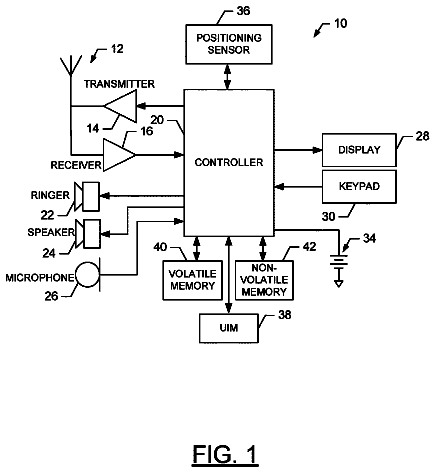
FIG. 6 is a block diagram illustrating an example mobile device capable of implementing aspects of the embodiments disclosed herein.
FIG. 7 schematically illustrates a network, according to an illustrative embodiment.
Detailed description
While the subject matter described herein may be presented, at times, in the general context of program modules that execute in conjunction with the execution of an operating system and application programs on a computer system, those skilled in the art will recognize that other implementations may be performed in combination with other types of program modules. Generally, program modules include routines, programs, components, data structures, computer-executable instructions, and/or other types of structures that perform particular tasks or implement particular abstract data types. Moreover, those skilled in the art will appreciate that the subject matter described herein may be practiced with other computer systems, including hand-held devices, mobile devices, wireless devices, multiprocessor systems, distributed computing systems, microprocessor-based or programmable consumer electronics, minicomputers, mainframe computers, routers, switches, other computing devices described herein, and the like.
In the following detailed description, references are made to the accompanying drawings that form a part hereof, and in which are shown by way of illustration specific embodiments or examples. Referring now to the drawings, in which like numerals represent like elements throughout the several figures, example aspects of a consumer service cloud for implementing location-based services to control smart device operations will be presented.
Referring now to FIG. 1 , aspects of an illustrative operating environment 100 for various concepts disclosed herein will be described. It should be understood that the operating environment 100 and the various components thereof have been greatly simplified for purposes of discussion. Accordingly, additional or alternative components of the operating environment 100 can be made available without departing from the embodiments described herein.
The illustrated operating environment 100 includes a user equipment (“UE”) 102 that is in communication with an evolved packet core (“EPC”) 104 via an evolved Universal Mobile Telecommunications System Terrestrial Radio Access Network (“E-UTRAN”) 106 . The illustrated E-UTRAN 106 includes a plurality of eNode-Bs 108 A- 108 N (eNB_ 1 , eNB_ 2 , . . . eNB_n; collectively “eNBs 108 ”), each of which serves an area shown as a corresponding cell 110 A- 110 N (cell_ 1 , cell_ 2 , . . . cell_n; collectively “cells 110 ”). Although three eNBs and three corresponding cells are illustrated, implementations of the operating environment 100 may include a different number of eNBs and corresponding cells. As such, the illustrated example should not be construed as being limiting in any way.
The EPC 104 is in communication with a consumer service cloud (“CSC”) 112 that hosts intelligence in one or more CSC systems 114 for consumer service management. The CSC 112 can be leveraged by the UE 102 for location-based services, including, but not limited, to control smart devices, as will be described in greater detail herein.
The UE 102 may be a cellular telephone, a feature phone, a smartphone, a mobile computing device, a portable television, a portable video game console, other computing device, or any other user equipment that is configured to communicate with one or more one or more RANs, such as the E-UTRAN 106 , via one or more radio access components (best shown in FIG. 6 ). The radio access component(s) can include at least one transceiver that is compatible with Long-Term Evolution (“LTE”) to enable communications with the E-UTRAN 106 . The radio access component(s) can include one or more other transceivers to enable communications with other access networks (not shown) including, but not limited to, access networks that operate in accordance with Global System for Mobile communications (“GSM”), Code Division Multiple Access (“CDMA”) ONE, CDMA2000, and various other Third Generation Partnership Project (“3GPP”). Moreover, the other transceiver(s) may facilitate communications over various channel access methods (which may or may not be used by the aforementioned standards) including, but not limited to, Time-Division Multiple Access (“TDMA”), Frequency-Division Multiple Access (“FDMA”), Wideband CDMA (“W-CDMA”), Orthogonal Frequency-Division Multiplexing (“OFDM”), Space-Division Multiple Access (“SDMA”), and the like. The radio access component(s) also can include one or more transceivers to enable communications with WI-MAX and/or WI-FI networks (not shown). As such, the UE 102 may be a multi-mode device capable of communicating with the E-UTRAN 106 and at least one other RAN.
The EPC 104 can include a serving gateway (“SGW”), a packet data network (“PDN”) gateway (“PGW”), and a home subscriber server (“HSS”). The SGW can transport Internet Protocol (“IP”) data traffic between the UE 102 and one or more external networks, including, for example, an IP multimedia subsystem (“IMS”) network. The SGW connects the E-UTRAN 106 to the EPC 104 to allow IP data communications between the UE 102 and the EPC 104 . The SGW also performs operations to facilitate handover among eNBs, such as the eNBs 108 , within the E-UTRAN 106 and between other LTE and 3GPP access networks. The SGW is in communication with the PDN gateway. The PDN gateway interconnects the EPC 104 and external IP networks (i.e., PDNs—not shown). The PDN gateway routes IP packets to and from the PDNs. The PDN gateway also performs operations such as IP address/IP prefix allocation, policy control, and charging. In some implementations, the PDN gateway and the SGW are combined. The HSS is a database that contains user/subscriber information. The HSS also performs operations to support mobility management, call and session setup, user authentication, and access authorization.
The illustrated UE 102 is traveling in a direction of travel 116 through the E-UTRAN 106 , and more particularly, from the cell_ 1 110 A to the cell_ 2 110 B, and finally arriving at a smart device location 118 located in the cell_N 110 N. The smart device location 118 can be or can include any indoor environment, outdoor environment, or a combination thereof. Some example environments include, but are not limited to, buildings, single family homes, duplexes, triplexes, apartments, condominiums, stadiums, coliseums, theaters, tents, port-a-potties, stages, alleyways, subway tunnels, sewers, vehicle interiors, and the like. The smart device location 118 can include one or more smart devices 120 .
The smart device(s) 120 can include electronic devices capable of communication via one or more wireless networks for the exchange of data. The wireless network(s) (not shown) can employ one or more wireless protocols, some examples of which include, but are not limited to, BLUETOOTH, WI-FI, LTE and/or other mobile telecommunications protocols, and the like. The smart device(s) 120 can be user reconfigurable and might operate autonomously in some implementations. Some examples of the smart device(s) 120 include, but are not limited to, home automation devices, home security devices, smartphones, tablet computers, slate computers, smart watches, smart bands, smart key chains, smart wallets, smart televisions, smart set-top-boxes, smart refrigerators and other smart appliances, and the like.
The CSC 112 may include servers, databases, networks, applications, and/or other computing resources that are utilized by one or more cloud computing service providers to provide a cloud computing service to one or more users (consumers). A cloud computing service is defined herein as a service provided in accordance with a cloud computing model that enables ubiquitous, convenient, on-demand network access to a shared pool of configurable computing resources that can be rapidly provisioned and released with minimal management effort or service provider interaction. A cloud infrastructure is defined herein as the collection of hardware and software that enables a cloud computing service.
In some embodiments, the CSC 112 is configured to provide, at least in part, Software as a Service (“SaaS”). SaaS is defined herein as the capability provided to the user to use the provider's application operating on a cloud infrastructure. The applications are accessed by the user via various client devices, such as the UE 102 and/or the smart devices 120 , through either a thin client interface, such as a Web browser, or a program interface. The user does not manage or control the underlying cloud infrastructure including networks, servers, operating systems, storage, or individual application capabilities, with the possible exception of user-specific application configuration settings.
In some embodiments, the CSC 112 is configured to provide, at least in part, Platform as a Service (“PaaS”). PaaS is defined herein as the capability provided to the user to deploy onto a cloud infrastructure user-created or acquired applications created using programming languages, libraries, services, and/or tools supported by the provider. The user does not manage or control the underlying cloud infrastructure including networks, servers, operating systems, and storage, but has control over the deployed applications and possibly configuration settings for the application-hosting environment.
In some embodiments, the CSC 112 is configured to provide, at least in part, Infrastructure as a Service (“IaaS”). IaaS is defined herein as the capability provided to the user to provision processing, storage, networks, and other computing resources where the user is able to deploy and run arbitrary software, which can include operating systems and applications. The user does not manage or control the underlying cloud infrastructure, but has control over operating systems, storage, and deployed applications; and possibly limited control of select networking components (e.g., host firewalls).
In some embodiments, the CSC 112 is configured to provide, at least in part, a private cloud infrastructure. A private cloud infrastructure is defined herein as a cloud infrastructure that is provisioned for exclusive use by one user or a pre-defined group of two or more users. A private cloud infrastructure may be owned, managed, and operated by an organization (e.g., a telecommunications service provider), a third party, or some combination thereof. A private cloud infrastructure may exist on or off premises.
The CSC 112 , and more particularly, the CSC system 114 , can store, in a memory device (best shown in FIG. 5 ), CSC system data 122 that can include one or more user profiles 124 , one or more user identifiers 126 , one or more user equipment identifiers 128 , one or more mobility patterns 130 , one or more smart device identifiers 132 , a cell ID 134 of the smart device location 118 (i.e., a “home” cell ID associated with the smart device location 118 ), and one or more smart device settings 136 . Each of the user profiles 124 can include any data associated a particular user. The data can include at least a portion of the CSC system data 122 associated with the particular user.
Each of the user identifiers 126 can include a unique identifier that uniquely identifies a particular user. The user identifiers 126 each might include a unique combination of numbers, letters, and/or characters to identify a particular user. The user identifiers 126 each might include an international mobile subscriber identity (“IMSI”). The user identifiers 126 each might include a unique identifier for a user who subscribes to or otherwise utilizes one or more services, which might include a service provided, at least in part, via the smart device(s) 120 .
Each of the user equipment identifiers 128 can include a unique identifier that uniquely identifies a particular UE, such as the UE 102 . The user equipment identifiers 128 each might include a unique combination of numbers, letters, and/or characters. The user equipment identifiers 128 each might include an international mobile equipment identity (“IMEI”).
Each of the mobility patterns 130 can include a pattern of movement by a UE, such as the UE 102 , through the E-UTRAN 106 . The mobility patterns 130 can be used to predict departure/arrival times of UEs from/to one or more locations, such as the smart device location 118 , based upon visited cell history and detection. The visited cell history can include cell IDs associated with each cell that serves a location traversed by a UE.
Each of the smart device identifiers 132 can include a unique identifier that uniquely identifies a particular smart device. The smart device identifiers 132 each might include a combination of numbers, letters, and/or characters to identify a particular smart device.
The cell ID 134 of the smart device location 118 can include a unique identifier that uniquely identifies the cell 110 N in which the smart device location 118 is located. The cell ID 134 might include a UTRAN cell ID (“LCID”), a CID, or the like.
Each of the smart device settings 136 can include a setting that controls, at least in part, one or more operational aspects of one or more smart devices, such as the smart device(s) 120 . For example, the smart device 120 embodied as a smart thermostat, such as the NEST LEARNING THERMOSTAT, available from Nest Labs, Inc., might have one or more settings to control temperature, operation of an A/C unit, operation of a heating unit, operation of a heat pump unit, operation of a fan, or the like.
Example use cases for the CSC 112 implemented by the CSC system 114 will now be described. In these examples, a user (not shown) associated with the UE 102 is traveling to his/her home, which may be the smart device location 118 or may be located within the smart device location 118 . The CSC system 114 has knowledge of the home serving cell (cell_N 110 N in the illustrated example) associated with the user's home via the cell ID 134 . The CSC system 114 also has knowledge of the smart device setting(s) 136 .
As a first non-limiting example, the user desires to have the temperature adjusted in his/her home prior to arriving at the smart device location 118 . While the UE 102 travels to the smart device location 118 (the user's home in this example) through the cells 110 of the E-UTRAN 106 , the CSC 112 can receive UE location updates 138 from the EPC 104 regarding the location of the UE 102 as reported by the UE 102 to the EPC 104 . The UE 102 , an MME, an SGW, or a combination thereof can report, in the UE location update(s) 138 , the cell ID or tracking area identity (“TAI”) when the UE 102 enters each of the cells 110 . As part of a handover procedure, the UE 102 reports the cell ID to the serving eNB 108 that reports to the EPC 104 that, in turn, reports to the CSC 112 . In particular, the serving eNB 108 can report the cell ID to the MME and the SGW. The MME and the SGW can coordinate handover of the UE context and user data between the old and new eNB 108 . Upon completion of this process, the MME and/or the SGW can report the cell change to the CSC 112 .
If the UE 102 reports the cell ID 134 associated with the user's home serving cell (cell_N 110 N in the illustrated example), the CSC system 114 can generate a request 140 and can send the request 140 to the smart device 120 , which is embodied as a smart thermostat in this example. The request 140 can include one or more of the smart device settings 136 associated with the smart device 120 for when the user is traveling towards the smart device location 118 . In this example, the request 140 particularly includes a temperature setting for when the user is traveling towards the smart device location 118 . The smart device 120 can receive the request 140 and can adjust one or more operational aspects to change the temperature setting.
If the user leaves the smart device location 118 , the UE 102 can continue to provide the location updates 138 as the UE 102 travels from the cell_N 110 N to the cell_ 2 110 B. It is contemplated that patterns of cell changes (for example on the way home) can be learned and referenced over time, thus leading to more accurate predictions of the user's intended destination. In response, the CSC system 114 can generate a further request 142 and can send the further request 142 to the smart device 120 . The further request 142 can include one or more of the smart device settings 136 associated with the smart device 120 for when the user is traveling away from the smart device location 118 . In this example, the further request 142 particularly includes a temperature setting for when the user is traveling away from the smart device location 118 . The smart device 120 can receive the further request 142 and can adjust one or more operational aspects to change the temperature setting.
As a second non-limiting example, the user desires to disarm his/her home security system prior to arriving at the smart device location 118 . While the UE 102 travels to the smart device location 118 (the user's home in this example) through the cells 110 of the E-UTRAN 106 , the CSC 112 can receive the UE location updates 138 from the EPC 104 regarding the location of the UE 102 as reported by the UE 102 to the EPC 104 . The UE 102 can report, in the UE location update(s) 138 , the cell ID or TAI when the UE 102 enters each of the cells 110 . If the UE 102 reports the cell ID 134 associated with the user's home serving cell (cell_N 110 N in the illustrated example), the CSC system 114 can generate the request 140 and can send the request 140 to the smart device 120 , which is embodied as a home security system in this example. The request 140 can include one or more of the smart device settings 136 associated with the smart device 120 for when the user is traveling towards the smart device location 118 . In this example, the request 140 particularly includes a disarm setting for when the user is traveling towards the smart device location 118 . The smart device 120 can receive the request 140 and can adjust one or more operational aspects to unarm the security system.
If the user leaves the smart device location 118 , the UE 102 can continue to provide the location updates 138 as the UE 102 travels from the cell_N 110 N to the cell_ 2 110 B. In response, the CSC system 114 can generate the further request 142 and can send the further request 142 to the smart device 120 . The further request 142 can include one or more of the smart device settings 136 associated with the smart device 120 for when the user is traveling away from the smart device location 118 . In this example, the further request 142 particularly includes an arm/re-arm setting for when the user is traveling away from the smart device location 118 . The smart device 120 can receive the further request 142 and can adjust one or more operational aspects to arm/re-arm the security system.
It should be understood that some implementations of the operating environment 100 may include additional functionality or include less functionality than described above. Thus, the illustrated embodiment should be understood as being illustrative, and should not be construed as being limiting in any way.
Turning now to FIG. 2 , a flow diagram illustrating aspects of a method 200 for remotely controlling one or more operational aspects of one or more smart devices, such as the smart device(s) 120 , will be described, according to an illustrative embodiment. It should be understood that the operations of the illustrative methods disclosed herein are not necessarily presented in any particular order and that performance of some or all of the operations in an alternative order(s) is possible and is contemplated. The operations have been presented in the demonstrated order for ease of description and illustration. Operations may be combined, separated, added, omitted, modified, and/or performed simultaneously or in another order without departing from the scope of the subject disclosure.
It also should be understood that the illustrated methods can be ended at any time and need not be performed in their entirety. Some or all operations of the methods, and/or substantially equivalent operations, can be performed by execution of computer-executable instructions included on a computer-readable storage media, as defined below. The term “computer-executable instructions,” and variants thereof, as used in the description and claims, is used expansively herein to include routines, application programs, software, application modules, program modules, components, data structures, algorithms, and the like. Computer-executable instructions can be implemented on various system configurations, including single-processor or multiprocessor systems, distributed computing systems, minicomputers, mainframe computers, personal computers, hand-held computing devices, microprocessor-based, programmable consumer electronics, combinations thereof, and the like.
Thus, it should be appreciated that the logical operations described herein may be implemented
as a sequence of computer implemented acts or program modules running on a computing system and/or
as interconnected machine logic circuits or circuit modules within the computing system. The implementation is a matter of choice dependent on the performance and other requirements of the computing system. Accordingly, the logical operations described herein are referred to variously as states, operations, structural devices, acts, or modules. These operations, structural devices, acts, and modules may be implemented in software, in firmware, in special purpose digital logic, and any combination thereof.
The method 200 includes operations performed by the CSC system 114 via execution, by one or more processors, of one or more software program modules (best shown in FIG. 5 ). The method 200 is described with additional reference to FIG. 1 . The method 200 begins and proceeds to operation 202 , where the CSC system 114 determines a cell ID associated with a location of a smart device, such as the cell ID 134 associated with the smart device(s) 120 located in the smart device location 118 . In some embodiments, the smart device(s) 120 can connect to the EPC 104 via the eNB_n 108 N to provide the cell ID 134 associated therewith in the cell_N 110 N, for example, as part of a setup process. Also during the setup process, the smart device(s) 120 can communicate with the CSC system 114 to associate the smart device identifier(s) 132 with one or more of the user profiles 124 , establish which of the smart device settings 136 can be changed, associate the cell ID 134 with the smart device identifier(s), and/or perform other operations to establish communications between the smart device(s) 120 and the CSC system 114 . The setup process might be manual based upon input from one or more users, semi-automatic based, at least in part, upon input from the user(s), or automatic, wherein the smart device(s) 120 communicate with the CSC system 114 automatically upon being powered on.
From operation 202 , the method 200 proceeds to operation 204 , where the CSC system 114 periodically receives the current cell ID associated with the cell 110 in which the UE 102 is located via the UE location update(s) 138 . The UE 102 can provide the UE location update(s) 138 during, for example, a handover process as the UE 102 moves from cell to cell (e.g., from the cell_ 1 110 A to the cell_ 2 110 B and then from the cell_ 2 110 B to the cell_N 110 N). The UE 102 might provide the UE location update(s) 138 at other times, including, for example, when the UE 102 is powered on, when the UE 102 experiences a change in signal strength, and/or in response to a request from the EPC 104 (which might be prompted by a request from the CSC system 114 ).
From operation 204 , the method 200 proceeds to operation 206 , wherein the CSC system 114 determines whether the cell ID received in the UE location update 138 matches the cell ID 134 associated with the smart device location 118 . The CSC system 114 might determine whether the cell ID received in the UE location update 138 matches the cell ID 134 associated with the smart device location 118 each time a UE location update 138 is received. The CSC system 114 might determine whether the cell ID received in the UE location update 138 matches the cell ID 134 associated with the smart device location 118 at some other interval, which may be based upon time or a number of UE location updates 138 received, for example. If, at operation 206 , the CSC system 114 determines that the cell ID received in the UE location update 138 does not match the cell ID 134 associated with the smart device location 118 , the method 200 returns to operation 204 , where the CSC system 114 waits to receive another UE location update 138 . If, however, at operation 206 , the CSC system 114 determines that the cell ID received in the UE location update 138 does match the cell ID 134 associated with the smart device location 118 , the method 200 proceeds to operation 208 .
At operation 208 , the CSC system 114 generates the request 140 to adjust one or more of the smart device settings 136 to control one or more operational aspects of the smart device(s) 120 . From operation 208 , the method 200 proceeds to operation 210 , where the CSC system 114 provides the request 140 to the smart device(s) 120 via the EPC 104 . From operation 210 , the method 200 proceeds to operation 212 , where the method 200 ends.
Turning now to FIG. 3 , a flow diagram illustrating aspects of a method 300 for remotely controlling one or more operational aspects of one or more smart devices, such as the smart device(s) 120 , will be described, according to an illustrative embodiment. The method 300 includes operations performed by the CSC system 114 via execution, by one or more processors, of one or more software program modules (best shown in FIG. 5 ). The method 300 is described with additional reference to FIG. 1 .
The method 300 begins and proceeds to operation 302 , where the CSC system 114 periodically receives the current cell ID associated with the cell_ 110 in which the UE 102 is located via the UE location update(s) 138 . The UE 102 can provide the UE location update(s) 138 during, for example, a handover process as the UE 102 moves from cell to cell (e.g., from the cell_ 1 110 A to the cell_ 2 110 B and then from the cell_ 2 110 B to the cell_N 110 N). The UE 102 might provide the UE location update(s) 138 at other times, including, for example, when the UE 102 is powered on, when the UE 102 experiences a change in signal strength, and/or in response to a request from the EPC 104 (which might be prompted by a request from the CSC system 114 ).
From operation 302 , the method 300 proceeds to operation 304 , where the CSC system 114 determines whether a mobility pattern, such as one of the mobility patterns 130 has been established for the UE 102 . The mobility patterns 130 can include a pattern of movement by the UE 102 , through the E-UTRAN 106 . The mobility patterns 130 can be used to predict departure/arrival times of UEs from/to one or more locations, such as the smart device location 118 , based upon visited cell history and detection. The visited cell history can include cell IDs associated with each cell that serves a location traversed by a UE. If, at operation 304 , the CSC system 114 determines that a mobility pattern has not been established for the UE 102 , the method 300 proceeds to operation 306 , where the CSC system 114 determines, based upon the UE location update(s) 138 , a mobility pattern associated with the UE 102 . The CSC system 114 can then store the newly determined mobility pattern as one of the mobility patterns 130 associated with the UE 102 .
From operation 306 , or if the CSC system 114 determines, at operation 304 , that a mobility pattern 130 has been established for the UE 102 , the method 300 proceeds to operation 308 . At operation 308 , the CSC system 114 determines based at least in part upon the mobility pattern 130 that a current cell ID associated with the location of the UE 102 will match the cell ID 134 associated with the smart device location 118 within a predefined time period.
From operation 308 , the method 300 proceeds to operation 310 , where the CSC system 114 generates the request 140 to adjust one or more of the smart device settings 136 to control one or more operational aspects of the smart device(s) 120 . From operation 310 , the method 200 proceeds to operation 312 , where the CSC system 114 provides the request 140 to the smart device(s) 120 via the EPC 104 . From operation 312 , the method 300 proceeds to operation 314 , where the method 300 ends.
Turning now to FIG. 4 , a flow diagram illustrating aspects of a method 400 for remotely controlling one or more operational aspects of one or more smart devices, such as the smart device(s) 120 , will be described, according to an illustrative embodiment. The method 400 includes operations performed by the CSC system 114 via execution, by one or more processors, of one or more software program modules (best shown in FIG. 5 ). The method 400 is described with additional reference to FIG. 1 .
The method 400 begins and proceeds to operation 402 , where the CSC system 114 determines that the UE 102 has left the smart device location 118 . For example, the CSC system 114 can receive one of the UE location updates 138 during, for example, a handover process as the UE 102 moves from the smart device location 118 in the cell_N 110 N to the cell_ 2 110 B. The UE 102 might provide the UE location update(s) 138 at other times, including, for example, when the UE 102 is powered on, when the UE 102 experiences a change in signal strength, and/or in response to a request from the EPC 104 (which might be prompted by a request from the CSC system 114 ).
From operation 402 , the method 400 proceeds to operation 404 , where the CSC system 114 generates the further request 142 to adjust one or more of the smart device settings 136 to control one or more operational aspects of the smart device(s) 120 . From operation 404 , the method 400 proceeds to operation 406 , where the CSC system 114 provides the further request 142 to the smart device(s) 120 via the EPC 104 . From operation 406 , the method 400 proceeds to operation 408 , where the method 400 ends.
FIG. 5 is a block diagram illustrating a computer system 500 configured to provide the functionality in accordance with various embodiments of the concepts and technologies disclosed herein. In some implementations, the UE 102 , the smart device(s) 120 , the CSC system 114 , and/or the eNBs 108 can utilize an architecture that is the same as or similar to the architecture of the computer system 500 , or a modified version thereof. It should be understood, however, that modification to the architecture may be made to facilitate certain interactions among elements described herein.
The computer system 500 includes a processing unit 502 , a memory 504 , one or more user interface devices 506 , one or more input/output (“I/O”) devices 508 , and one or more network devices 510 , each of which is operatively connected to a system bus 512 . The bus 512 enables bi-directional communication between the processing unit 502 , the memory 504 , the user interface devices 506 , the I/O devices 508 , and the network devices 510 .
The processing unit 502 may be a standard central processor that performs arithmetic and logical operations, a more specific purpose programmable logic controller (“PLC”), a programmable gate array, a system-on-a-chip, or other type of processor known to those skilled in the art and suitable for controlling the operation of the server computer. Processing units are generally known, and therefore are not described in further detail herein.
The memory 504 communicates with the processing unit 502 via the system bus 512 . In some embodiments, the memory 504 is operatively connected to a memory controller (not shown) that enables communication with the processing unit 502 via the system bus 512 . The memory 504 includes an operating system 518 and one or more program modules 516 . The operating system 518 can include, but is not limited to, members of the WINDOWS, WINDOWS CE, and/or WINDOWS MOBILE families of operating systems from MICROSOFT CORPORATION, the LINUX family of operating systems, the SYMBIAN family of operating systems from SYMBIAN LIMITED, the BREW family of operating systems from QUALCOMM CORPORATION, the MAC OS, iOS, and/or LEOPARD families of operating systems from APPLE CORPORATION, the FREEBSD family of operating systems, the SOLARIS family of operating systems from ORACLE CORPORATION, other operating systems, and the like.
The program modules 516 may include various software and/or program modules to perform the various operations described herein. The program modules 516 and/or other programs can be embodied in computer-readable media containing instructions that, when executed by the processing unit 502 , perform one or more of the methods 200 , 300 , 400 or at least a portion thereof, described in detail above with respect to FIGS. 2-4 , respectively. According to embodiments, the program modules 516 may be embodied in hardware, software, firmware, or any combination thereof. Although not shown in FIG. 5 , it should be understood that the memory 504 , in embodiments that the CSC system 114 is configured like the computer system 500 , also can be configured to store at least a portion of the CSC system data 122 , and/or other data.
By way of example, and not limitation, computer-readable media may include any available computer storage media or communication media that can be accessed by the computer system 500 . Communication media includes computer-readable instructions, data structures, program modules, or other data in a modulated data signal such as a carrier wave or other transport mechanism and includes any delivery media. The term “modulated data signal” means a signal that has one or more of its characteristics changed or set in a manner as to encode information in the signal. By way of example, and not limitation, communication media includes wired media such as a wired network or direct-wired connection, and wireless media such as acoustic, RF, infrared and other wireless media. Combinations of the any of the above should also be included within the scope of computer-readable media.
The description continues in the full USPTO document.
 Lapsed, fee not paid6 drawings

