 Lapsed, fee not paid42 drawings
Sports & Fitness · US 9,841,824 B2
Combination computing device and game controller with flexible bridge and supporting a keyboard module
A combination computing device and input device.
US 9,842,491 B2 · Assignee: Sure Universal Ltd. · Inventors: Ariel; Viktor et al.
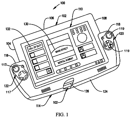
Sheet 1 of 16 from the published document. All sheets in the USPTO PDF
Disclosed is a universal remote control device including a display to provide a graphical unit interface (GUI), a controller configured to process registration requests from state machines associated with remotely controllable appliances and to manage control data transfer to and from the state machines responsive to the registration requests, and a communication module to enable communications between the device and the state machines. Additionally disclosed is a graphics interface unit (GUI) implementable on a display of a computing device operable to remotely control a plurality of appliances. The GUI includes a screen area on the display to display output information, and a plurality of sections on the display to simultaneously display input selection functions associated with different levels of a hierarchical arrangement of control functions for the plurality of appliances.
Remote control devices to allow a user to remotely control the operation of electrical and electronic appliances are well known and have been around for many decades. In the earlier days, manufacturers configured appliances to operate with a dedicated remote control device which was programmed with a particular identification code which allowed the device to pair with the appliance, generally communicating using infrared (IR) or radio frequency (RF) communications to control the device. Each appliance required its own remote control device so that a household frequently found itself with numerous remote control devices for controlling the various televisions, air conditioners, and other controllable appliances generally found in a typical home. In order to solve the problem of dealing with multiple remote control devices, universal remote control devices were developed. These were prepro
8 of 16 drawing sheets so far from the published document, cropped to the drawing. Every sheet is in the USPTO PDF.
What the patent claimed, word for word. All of it is now free to use.
The present invention relates to electronic and electrical appliances generally and to a system and method of remotely controlling these appliances in particular.
Remote control devices to allow a user to remotely control the operation of electrical and electronic appliances are well known and have been around for many decades. In the earlier days, manufacturers configured appliances to operate with a dedicated remote control device which was programmed with a particular identification code which allowed the device to pair with the appliance, generally communicating using infrared (IR) or radio frequency (RF) communications to control the device. Each appliance required its own remote control device so that a household frequently found itself with numerous remote control devices for controlling the various televisions, air conditioners, and other controllable appliances generally found in a typical home.
In order to solve the problem of dealing with multiple remote control devices, universal remote control devices were developed. These were preprogrammed with a relatively large number of identification codes which allowed the device to pair with those appliances whose identification codes were among those programmed into the device, thereby allowing control of numerous appliances. Nevertheless, these universal remote control devices were limited to controlling only those appliances whose identification codes were preprogrammed into the device, and required extensive amounts of time to locate the correct identification code for each appliance from among all those stored in the device.
With technological advancements and the increase in popularity of the Internet, universal remote control devices were developed as part of systems which could access databases through the Internet in order to download the identification codes to the devices. These databases generally stored a large number of identification codes suitable to allow the remote control devices to communicate with and control a large number of appliances of different types and from different manufacturers. An example of such a system is described in U.S. Pat. No. 7,586,398 B2 to Huang et al., which discloses “A system and method for using an RFID tag to automatically setup and configure a universal remote control to command appliances of various types and various manufacturers”. Another example of such system is described in US Patent Application Publication No. 2012/0295662 A1 to Haubrich which discloses “A universal remote control system and method for employing a centralized database for programming the universal remote control (URC) to control the operation of appliance(s). The appliance(s) may or may not be made by different manufactures. The centralized database is accessible via the Internet and includes many different appliances made by many different manufacturers. The user may access a web site of the centralized database and manually enter electronic appliances identifying data that the URC is desired to operate, and then the centralized database sends the appropriate command code data to the URC either directly or temporarily downloads them into a computer to be later loaded into the URC. The centralized database includes command codes for appliances such as TV sets, DVDs, CD systems, alarm clocks, and VCRs, music synthesizers, toys, stereo systems, ovens, washing machines, timers, power strips, and the like”.
More recently, with the explosive increase in the global use of smartphones and their continuously-expanding processing power, the trend is to implement universal remote control devices in the smartphones. Numerous application programs have been developed which allow a user to control electronic multi-media devices and other electronic and electrical appliances from a smartphone. U.S. Pat. No. 8,519,820 B2 to Cannistraro discloses “Systems and methods for saving and restoring scenes in a multimedia system with minimal configuration are provided. The techniques of the present invention can allow the states of the components in the multimedia system to be captured in a scene. Once the scene has been saved, the scene can be restored at a later time. A remote control system for recommending scenes by comparing states of components in the current scene with states of components in saved scenes is also provided. The remote control system can also recommend scenes based on usage patterns. Moreover, the remote control system can allow users to designate one or more saved scenes as favorite scenes”.
There is provided, in accordance with an embodiment of the present invention, a universal remote control device including a display to provide a graphical unit interface (GUI), a controller configured to process registration requests from state machines associated with remotely controllable appliances and to manage control data transfer to and from the state machines responsive to the registration requests, and a communication module to enable communications between the device and the state machines.
According to an embodiment of the present invention, the controller includes a state machine module to process the registration requests and to manage the control data transfer.
According to an embodiment of the present invention, the state machine module includes a state machine register to store message codes associated with the registration requests.
According to an embodiment of the present invention, the controller includes a selection wizard module to allow a user to manipulate the GUI.
According to an embodiment of the present invention, the controller includes a control panel hierarchy module to control a hierarchical arrangement of the GUI.
According to an embodiment of the present invention, the GUI is configured to simultaneously display several levels of the hierarchical arrangement on the display.
According to an embodiment of the present invention, the universal remote control device additionally includes a memory module to store state machine selection and control data.
According to an embodiment of the present invention, the memory module includes one or more databases to store the selection and control data according to a communication method between the device and the state machines.
According to an embodiment of the present invention, the memory module includes a database to store the selection and control data manually input by a user.
According to an embodiment of the present invention, the selection and control data is downloaded to the one or more databases from an appliance data server.
According to an embodiment of the present invention, the communication module includes an Internet connection unit to connect over the Internet with a database to download the selection and control data to the one or more databases.
According to an embodiment of the present invention, the communication module includes an Internet connection unit to connect over the Internet with a database to upload device usage information to a database.
According to an embodiment of the present invention, the communications module includes means to communicate between the device and the state machines using any one or any combination of Wi-Fi, infrared (IR), and radio frequency (RF) communications.
There is provided, in accordance with an embodiment of the present invention, a method of remotely controlling appliances, the method includes communicating between a universal remote controller and state machines associated with remotely controllable appliances, processing registration requests from the state machines on the remote controller, and managing control data transfer between the remote controller and the state machines responsive to the registration requests.
According to an embodiment of the present invention, the method additionally includes storing message codes associated with the registration requests in the remote controller.
According to an embodiment of the present invention, the method additionally includes storing selection and control data in a database in the remote controller according to a communications method between the remote controller and the state machines.
According to an embodiment of the present invention, the method additionally includes downloading the selection and control data from a database over the Internet.
According to an embodiment of the present invention, the method additionally includes storing manually input data by a user in a database in the remote controller.
According to an embodiment of the present invention, the method additionally includes uploading remote controller usage data to a database over the Internet.
According to an embodiment of the present invention, communicating includes using any one or any combination of Wi-Fi, infrared (IR), and radio frequency (RF) communications.
According to an embodiment of the present invention, the method additionally includes operating a graphical unit interface (GUI) in the remote controller to transfer the control data between the remote controller and the state machines
According to an embodiment of the present invention, the method additionally includes controlling a hierarchical arrangement of the GUI.
According to an embodiment of the present invention, the method additionally includes simultaneously displaying several levels of the hierarchical arrangement on a display.
There is provided, in accordance with an embodiment of the present invention, a remote control system for remotely controlling appliances including a universal remote control device including a display to provide graphical unit interface (GUI), a controller configured to process registration requests from state machines associated with remotely controllable appliances and to manage control data transfer to and from the state machines responsive to the registration requests, and a communication module to enable communications between the device and the state machines. The remote control system additionally includes a usage data server to upload and process device usage information, and an appliance data server to download selection and control data associated with the state machines to the remote controller.
According to an embodiment of the present invention, the communication module includes an Internet connection unit to connect over the Internet with the usage data server and the appliance data server.
There is provided, in accordance with an embodiment of the present invention, a graphics interface unit (GUI) implementable on a display of a computing device operable to remotely control a plurality of appliances, the GUI includes a screen area on the display to display output information, and a plurality of sections on the display to simultaneously display input selection functions associated with different levels of a hierarchical arrangement of control functions for the plurality of appliances.
According to an embodiment of the present invention, a top level of the hierarchical arrangement is associated with different groups of any one of appliance types and appliance sets.
According to an embodiment of the present invention, a secondary level of the hierarchical arrangement is associated with different appliances within a group of appliance types or appliance sets, and wherein the secondary level is displayed on an appliance selection section of the display.
According to an embodiment of the present invention, a tertiary level of the hierarchical arrangement is associated with different functional features of an appliance, and wherein the tertiary level is displayed on a panel selection section of the display.
According to an embodiment of the present invention, a quaternary level of the hierarchical arrangement is associated with different elements of a functional feature of an appliance, and wherein the quaternary level is displayed on a control panel section of the display.
According to an embodiment of the present invention, the input selection functions include selector buttons.
According to an embodiment of the present invention, the plurality of sections includes a control panel section, a panel selector section, and an appliance selector section.
According to an embodiment of the present invention, the control panel section is located on the display below the screen area, the panel selector section is located below the control panel section, and the appliance selector section is located to the left of the control panel.
According to an embodiment of the present invention, the appliance selector section and the panel selector section include slider bars.
The subject matter regarded as the invention is particularly pointed out and distinctly claimed in the concluding portion of the specification. The invention, however, both as to organization and method of operation, together with objects, features, and advantages thereof, may best be understood by reference to the following detailed description when read with the accompanying drawings in which:
FIG. 1 schematically illustrates a universal remote control system, according to an exemplary embodiment of the present invention;
FIG. 2 schematically illustrates a functional diagram of an exemplary event-driven architecture (EDA) for use in the universal remote control system, according to an embodiment of the present invention;
FIG. 3A schematically illustrates a functional diagram of the EDA with state machines registered to a switch and a conflict manager, according to an embodiment of the present invention;
FIG. 3B schematically illustrates a process diagram of the EDA based on the state machine registrations depicted in FIG. 3A , according to an exemplary embodiment of the present invention;
FIG. 4 schematically illustrates a functional process diagram of data flow in the switch, according to an exemplary embodiment of the present invention;
FIG. 5 schematically illustrates a functional process diagram of data flow in the conflict manager, according to an exemplary embodiment of the present invention;
FIG. 6A schematically illustrates a functional process diagram of data flow in the state machines, according to an exemplary embodiment of the present invention;
FIG. 6B is a block diagram showing exemplary state machines which may be used in the universal remote control system, according to an exemplary embodiment of the present invention;
FIG. 7 schematically illustrates an exemplary functional layout of a GUI suitable for use with the computing device, according to an embodiment of the present invention;
FIG. 8 schematically illustrates an exemplary general remote control screen in the GUI for a remote controller for an appliance, according to an embodiment of the present invention;
FIG. 9 schematically illustrates an exemplary multiple appliance control screen in the GUI, according to an embodiment of the present invention;
FIG. 10 schematically illustrates an exemplary smart TV remote control screen in the GUI, according to an embodiment of the present invention;
FIG. 11 schematically illustrates an exemplary streaming media control screen in the GUI, according to an embodiment of the present invention;
FIG. 12 schematically illustrates an exemplary mouse/keyboard control screen in the GUI, according to an embodiment of the present invention;
FIG. 13 schematically illustrates an exemplary gyro-gesture/keyboard control screen in the GUI, according to an embodiment of the present invention; and
FIG. 14 schematically illustrates an exemplary applications control screen in the GUI, according to an embodiment of the present invention.
It will be appreciated that for simplicity and clarity of illustration, elements shown in the figures have not necessarily been drawn to scale. For example, the dimensions of some of the elements may be exaggerated relative to other elements for clarity. Further, where considered appropriate, reference numerals may be repeated among the figures to indicate corresponding or analogous elements.
In the following detailed description, numerous specific details are set forth in order to provide a thorough understanding of the invention. However, it will be understood by those skilled in the art that the present invention may be practiced without these specific details. In other instances, well-known methods, procedures, and components have not been described in detail so as not to obscure the present invention.
Unless specifically stated otherwise, as apparent from the following discussions, it is appreciated that, throughout the specification, discussions utilizing terms such as “processing,” “computing,” “calculating,” “determining,” or the like, refer to the action and/or processes of a computer, computing system, or similar electronic computing device that manipulates and/or transforms data represented as physical, such as electronic, quantities within the computing system's registers and/or memories into other data similarly represented as physical quantities within the computing system's memories, registers or other such information storage, transmission or display devices.
Embodiments of the present invention may include apparatus for performing the operations herein. This apparatus may be specially constructed for the desired purposes, or it may comprise a general-purpose computer selectively activated or reconfigured by a computer program stored in the computer. Such a computer program may be stored in a computer readable storage medium, such as, but not limited to, any type of disk, including floppy disks, optical disks, magnetic-optical disks, read-only memories (ROMs), compact disc read-only memories (CD-ROMs), random access memories (RAMs), electrically programmable read-only memories (EPROMs), electrically erasable and programmable read only memories (EEPROMs), magnetic or optical cards, Flash memory, or any other type of media suitable for storing electronic instructions and capable of being coupled to a computer system bus.
The processes and displays presented herein are not inherently related to any particular computer or other apparatus. Various general-purpose systems may be used with programs in accordance with the teachings herein, or it may prove convenient to construct a more specialized apparatus to perform the desired method. The desired structure for a variety of these systems will appear from the description below. In addition, embodiments of the present invention are not described with reference to any particular programming language. It will be appreciated that a variety of programming languages may be used to implement the teachings of the invention as described herein.
Applicants have realized that one of the major drawbacks with known universal remote control devices is that they generally require configuring the device and the appliance to be controlled, to make them compatible for most, if not all, modes of operation. This compatibility issue generally applies both to the older handheld dedicated universal remote control devices as well as to the newer, Internet-connectable mobile devices, including smartphones (the Internet-connectable mobile devices may also be referred to hereinafter as “remote control device”, “universal remote control device” or “device”). This typically requires that a user search for the identification code of each appliance which is to be controlled, and may additionally require that the user configure a set of parameters in each appliance and/or in the remote control device to pair the devices for each mode of operation. Performing these tasks may require that the user have some technical understanding of each appliance's operation, and frequently may result in user failure to successfully configure the remote control device and/or the appliance with the correct parameters. Not only may this be very frustrating for the user, but many times, the user may be faced with little choice but to call a technician to come to perform the configuring (which may be expensive and time consuming).
Applicants have further realized that a universal remote control system which is based on using an event-driven architecture substantially overcomes the previously described drawback of requiring the user (or somebody on his behalf) to configure the remote control device and/or the appliances. Therefore, disclosed herein is a universal remote control system based on an event-driven architecture (EDA) which may individually and/or collectively control different types of electronic and electrical appliances. In the EDA, each application in an appliance is associated with a state machine configured to send messages to, and receive messages from, other state machines. The state machines may also be configured to monitor message transmissions between other state machines. The EDA may include an event and message handler (hereinafter referred to as “switch”) which may act as a message broker to automatically handle the transfer of messages between state machines, and a conflict manager to automatically resolve conflicts in transmitted messages between state machines.
The state machines may all be associated with a particular appliance, or with several appliances whose operation may be interrelated. Consequently, it may be appreciated, the remote control system may allow use of a single remote controller to individually control different types of appliances, and may additionally allow jointly controlling different appliance and types of appliances as a single appliance set.
Reference is now made to FIG. 1 which schematically illustrates a universal remote control system 100 , according to an exemplary embodiment of the present invention. Remote control system 100 may be EDA-based and may include one or more computing devices, for example, computing device 102 ; any combination of electrical and electronic appliances which may include WIFI appliances 104 , IR appliances 106 , and optional RF appliances 108 ; an optional WIFI/IR converter 112 ; a usage data server 110 and an appliance data server 111 . WIFI appliances 104 may be any one or more electronic or electric appliances which may be remotely controlled using WIFI communications, and may include, for example, smart TVs and other multi-media devices, stereos, DVDs, set top boxes, coffee machines, washing and drying machines, refrigerators, ovens including microwave ovens, light switches, security systems, window shutters, garage doors, among many other appliances which may be remotely controlled using WIFI communications. IR appliances 106 may be any one or more types of electronic and electrical appliance which may be remotely controlled using IR communications, and may include all appliances known in the art as “legacy” appliances. RF appliances 108 may be any one or more types of electronic and electrical appliance which may be remotely controlled using RF communications, which may include Bluetooth (BT) communications, Near Field communication (NFC), RFID (radio frequency identification), among other types of RF communication technologies suitable for remotely controlling electrical and electronic appliances.
Computing device 102 may include a controller module 114 , a communication module 116 , a memory storage module 118 , and a display 120 . Computing device 102 may serve as a universal remote control device and may preferably be, although not limited to, a handheld computing device and may include, for example, a smartphone, a tablet, or a dedicated Internet-connectable handheld remote control device. Computing device 102 may discover and pair with any one or more of WIFI appliances 104 , IR appliances 106 , and optional RF appliances 108 , to remotely control their operation.
Computing device 102 may additionally be configured to download content from the Internet 122 and to stream the content to any of the paired appliances suitably configured to receive streaming content. Additionally or alternatively, the content may be stored in computing device 102 and may be streamed to any of the suitably configured appliances as desired by a user of the computing device.
Computing device 102 may connect through the Internet 122 to appliance data server 111 to download identification codes for WIFI appliances 104 , IR appliances 106 , and RF appliances 108 , which may be stored in a database in the server. Computing device 102 may additionally download from appliance data server 111 data which may be used for the operation of the computing device as a universal remote control device and for use in the operation of universal remote control system 100 , including data associated with the operation of the EDA, and which may include, aside from the information codes for the different types of appliances, data associated with the application programs of the appliances and with the operation of the switch and the conflict manager, including update information. Additionally or alternatively to connecting to appliance data server 111 through the Internet 122 , computing device may connect to the server through other connection means well known in the art for server/user data transfer.
Computing device 102 may upload data through the Internet 122 to usage data server 110 which may be associated with identification data associated with the computing device itself or with a user of the computing device. The uploaded data may additionally include information which may be processed by usage data server 110 to determine computing device 102 usage characteristics, for example, frequency of usage or hours of usage of the different types of appliances included in WIFI appliances 104 , IR appliance 106 , and RF appliances 108 , among many other types of data which may be uploaded and may be associated with computing device 102 usage characteristics. Additional data which may be uploaded to usage data server 110 may include data input by a user or automatically generated by the device such as, for example, new identification codes for remotely controlled appliances, results of conflict management functions as described further on herein, among all types of different data which may be uploaded from the computing device 102 to enhance system 100 operation.
It may be appreciated by the skilled person that the functions performed by usage data server 110 and appliance data server 111 , although described herein as two separate servers, may be functionally performed by one server which may integrate the functions performed by both servers. It may be further appreciated, that the distribution of functions as described above are not intended to be limiting, and that some of the functions described as being performed by one server may be performed by the other server, and vice versa. It may be additionally appreciated that usage data server 110 and appliance data server 111 may communicate with one another over the Internet 122 , or through other means known in the art, to exchange data between them, including data which may be processed by one server and stored in the other server.
Communication module 116 may include a WIFI connection unit 130 to allow communication between computing device 102 and WIFI appliances 104 . WIFI connection unit 130 may optionally communicate with WIFI/IR converter 112 to enable WIFI communication between computing device 102 and IR appliances 106 fitted with the WIFI/IR converter. Communication module 116 may additionally include an IR connection unit 132 to allow communication between computing device 102 and IR appliances 106 . Communication module 116 may additionally include a RF connection unit 134 to allow communication between computing device 102 and RF appliances 108 . Communication module 116 may additionally include an Internet connection unit 136 to allow Internet connections between computing device 102 over the Internet 122 , including with usage data server 110 and appliance data server 111 .
Controller module 114 may include a state machine module 123 , a selection wizard module 124 , a control panel hierarchy module 126 , and a tester module 128 . State machine module 123 may serve as the core of the EDA architecture and may monitor the state of the state machines associated with each appliance and may additionally trigger changes in the states. The changes in the states may be triggered responsive to user initiated operations or responsive to the monitoring, and may include use of a switch and a conflict manager, as will be described further on below in greater detail with reference to FIGS. 2A-6B . State machine module 123 may include a state machine register 125 to temporarily store data associated with the state of each state machine, including message codes as also described further on below.
Selection wizard module 124 may serve to guide a user operating computing device 102 to facilitate automatic discovery and pairing with WIFI appliances 104 , IR appliances 106 , RF appliances 108 , and to facilitate automatic downloading and uploading of data to and from usage data server 110 and appliance data server 111 . It may also guide a user to facilitate controlling the various appliances. Selection wizard module 124 may interface with memory 118 to store data into, and access data from, an optional IR appliance database 138 , an optional WIFI/RF appliance database 140 , and an optional USER appliance database 142 , which may be included in the memory. Associated with selection wizard module 124 may be tester module 128 which may serve to test the user's selection of control buttons for new appliances and may provide the user with performance feedback to allow the user to potentially select the most suitable control buttons.
Control panel hierarchy module 126 may control the arrangement of a display 120 as a graphical user interface (GUI) to allow hierarchical navigation through the various input and output panels displayed on the display. Display panel 120 may include four general areas where the input and output panels of the GUI may be hierarchically displayed, a control panel 144 , a screen 148 , an appliance selector 147 , and a panel selector 146 . Appliance selector 147 may include a slider bar with selector buttons to allow selection of an appliance from different appliances which may be controlled and are associated with a selected appliance type. Panel selector 146 may include a slider bar with selector buttons to allow selection of a panel from a number of different panels which may be used for control and are associated with a selected appliance. Control panel 144 may include selector buttons to allow selection of a feature (element) from the different features which may be controllable in an appliance and are associated with a selected panel. Screen 148 may serve for information display responsive to selections made for appliance control, but may display other type of information, which may include advertising and user information. A more detailed description of the GUI is provided further on below with reference to FIGS. 7-14 . IR appliance database 138 and WIFI/RF appliance database 140 may include discovery and pairing data downloaded to computing device 102 from appliance data server 111 . User appliance database 142 may include data input by the user and which may be associated with manually activated discovery and pairing functions which may be initiated by the user, and may include discovery and pairing data manually input by the user.
Reference is now made to FIG. 2 which schematically illustrates a functional diagram of an exemplary EDA 200 for use in universal remote control system 100 , according to an embodiment of the present invention. EDA 200 may include a switch 202 (message broker) and a conflict manager 204 which may be implemented in computing device 100 described in FIG. 1 , for example, in state machine module 123 . EDA 200 may additionally include one or more state machines 206 , for example state machines 1 - 4 as shown although many more state machines may be included.
Each state machine 206 may represent a logical unit which may be used to process a set of scenarios based on a set of autonomic states (i.e. an event handler) associated with each appliance, and may be capable of receiving messages from other state machines and sending messages to other state machines. The messages may include a message code associated with each state machine which may be used for identification purposes and which may be used for discovery and pairing state machines with one another.
Communications between state machines 206 may be through switch 202 which may act as a message broker. Conflict manager 204 may serve to interrupt messages sent from switch 202 to targeted state machines and may process the “interrupted” message and decide whether or not to block the message, to send as is, or to create and send another message instead.
In EDA 200 , each state machine 206 may support a logical unit which may be created to handle message logics and to optionally transmit messages to other state machines via switch 202 . Generally, each state machine 206 may register itself in switch 202 by registering relevant message codes it may be interested in receiving from the switch (stored in state machine register 125 ), and may then implement an event handler for each message code which is registered when a message arrives from the switch. Similarly, each state machine 206 may register itself in conflict manager 204 to monitor and report any messages with message codes which may be of conflict (stored in state machine register 125 ).
Reference is made to FIG. 3A which schematically illustrates a functional diagram of EDA 200 with state machines 206 registered to switch 202 and conflict manager 204 , according to an embodiment of the present invention. As may be appreciated from the figure, for exemplary purposes, state machine 1 is registered with switch 202 to receive messages with message code A while state machine 2 is registered with the switch to receive messages with message code A and/or with message code B. The registration of each state machine 206 associated with each particular code may be stored in switch 202 in a message code database 208 (see FIG. 4 ) in state machine register 125 . Message code database 208 may include a registration list 210 wherein may be listed, for each message code, the state machines which have registered to receive messages with that particular message code (see FIG. 4 ). For example, message code database 208 may include a registration list 210 for message code A which may include state machine 1 and state machine 2 , and may include a second registration list 210 for message code B which may include only state machine 2 .
State machines 3 and 4 are registered with conflict manager 204 to monitor message with message codes A and B, respectively. Similarly to switch 202 , registration of each state machine 206 associated with each particular code may be stored in conflict manager 204 in a message code database 216 (see FIG. 5 ) also in state machine register 125 . Message code database 216 may include a registration list 218 wherein may be listed, for each message code, the state machines which have registered for monitoring messages with that particular message code (see FIG. 5 ). For example, message code database 216 may include a registration list 218 for message code A which may include state machine 3 , and may include a second registration list 218 for message code B which may include only state machine 4 .
Reference is now also made to FIG. 3B which schematically illustrates a process diagram of EDA 200 based on the state machine registrations depicted in FIG. 3A , according to an exemplary embodiment of the present invention. It may be appreciated by the skilled person that the steps shown for the exemplary process are not intended to be limiting and that the process may be practiced with more or less steps, or with a different sequence of steps, or any combination thereof.
At 301 , state machine 1 may send a message with a message code A to switch 202 ;
At 302 , switch 202 may transfer the message to conflict manager 204 for conflict checking (to determine whether or not there is conflict);
At 303 , conflict manager 204 may transfer the message to state machine 3 who is registered with the conflict manager to monitor messages with message code A. Based on the response received from state machine 3 , conflict manager 204 may prevent switch 202 from transferring the message, may alter the message prior to transferring by the switch, or may instruct the switch to transfer the message as is;
At 304 , state machine 3 may return an OK message to conflict manager 204 indicative that there is no conflict;
At 305 , conflict manager 204 may instruct the switch 202 to send the message as is. Alternatively, should state machine 3 return an indication of conflict, conflict manager 204 may alter the message and send the altered message to switch 202 for transfer to the target state machines, or may cancel sending the received message completely;
At 306 , switch 202 may transfer the message with message code A to state machine 2 which is registered with the switch to receive message code A; and
At 307 , switch 202 may transfer the message with message code A to state machine 1 which is also registered with the switch to receive message code A.
Reference is now made to FIG. 4 which schematically illustrates a functional process diagram of data flow in switch 202 , according to an exemplary embodiment of the present invention. It may be appreciated by the skilled person that the steps shown for the exemplary process are not intended to be limiting and that the process may be practiced with more or less steps, or with a different sequence of steps, or any combination thereof.
At 401 , state machine 206 may send a message to switch 202 ;
At 402 , a message processor 212 in switch 202 may check in message code data base 208 for all state machines registered in registration list 210 to receive a message with the message code of the message received from state machine 206 ;
At 403 , message processor 212 may generate one or more messages 214 responsive to the received message for sending to all state machines listed in the associated registration list 210 ; and
At 404 , message processor 212 may send message 214 to conflict manager 204 for conflict checking.
Reference is now made to FIG. 5 which schematically illustrates a functional process diagram of data flow in conflict manager 204 , according to an exemplary embodiment of the present invention. It may be appreciated by the skilled person that the steps shown for the exemplary process are not intended to be limiting and that the process may be practiced with more or less steps, or with a different sequence of steps, or any combination thereof.
At 501 , conflict manager 204 may receive a message from switch 202 ;
At 502 , a message processor 220 in conflict manager 204 may check in message code data base 216 for all state machines registered in registration list 218 to monitor messages with the message code of the received message from switch 202 . In some embodiments, message processor 220 may be functionally replaced by message processor 212 in switch 202 so that message processor 212 also may access message code database 216 ;
At 503 , message processor 220 may send the message to be checked to all monitoring state machines 222 listed in registration list 218 for the particular message code. The message may be sent to state machines 222 either asynchronously or alternatively, synchronously;
At 504 , monitoring state machines 222 may send the results of the conflict monitoring check to message processor 220 for processing by the message processor;
The description continues in the full USPTO document.
About 6,274 words. The USPTO PDF has it with every drawing.
Fees are due 3.5, 7.5 and 11.5 years after grant. This patent expired on December 12, 2025, so the fee marked "not paid" was the one that went unpaid.
UNIVERSAL REMOTE CONTROL
Filed Sep 2015 · published Mar 2016STREAMING AND GAMING UNIVERSAL REMOTE CONTROLLER
Filed Sep 2015 · published Jun 2016Universal remote control
Filed Sep 2015 · granted Dec 2017Earlier publications, parents and continuations. None of them can still be enforced, or this patent would not be listed.
Prior art cited by the examiner or applicant. Useful when you check your own idea for novelty.
Everything on this page comes from the documents linked above.