Field of the invention and related art
The present invention relates to a filter frame for being provided, while holding a filter, e.g., in a path where air supply into an image forming apparatus or air discharge to an outside of the image forming apparatus and relates to a filter assembly.
In the image forming apparatus, a plurality of electrical parts (components) such as a motor and a power (voltage) source substrate are mounted and heat is given off by these parts. For this reason, conventionally, the air supply into the image forming apparatus and the air discharge to the outside of the image forming apparatus have been made. Further, when dirt and dust accumulate in the image forming apparatus or when the dirt and the dust float in the air in the image forming apparatus by being raised, there is a possibility that they are deposited on a surface of a recording material such as a sheet (paper) and thus an image quality lowers. For this reason, conventionally, a constitution in which a filter is provided for dust collection in a path for air supply or air discharge by a fan has been known.
This filter is held (supported) by a filter frame for being provided to a duct constituting a path for air supply or air discharge. For example, a constitution for holding a pleated filter formed so as to be repetitively folded up has been proposed (e.g., Japanese Laid-Open Patent Application (JP-A) (Kohyo) 2007-516829. In the case of the constitution disclosed in JP-A 2007-516829, a base portion (frame portion) constituting a filter frame is provided with a plurality of lateral ribs, and folds (pleats) of the pleated filter are disposed so as to be engaged with the lateral ribs. Then, in this state, a cover (frame portion) is superposed on the base portion, so that the filter is held.
Further, also a constitution for holding a flat plate(-shaped) filter has been proposed (e.g., JP-A H(Hei)11-63597). In the case of the constitution disclosed in JP-A H11-63597, in a state in which the filter is mounted on one of frames (frame portions) constituting a filter frame, the other frame (frame portion) is superposed on the one of frames (frame portions), so that the filter is held. In these cases of the constitution disclosed in JP-A 2007-516829 and JP-A H11-63597, it would be considered that the filter is held by being sandwiched between edge portions of the frame portions which are superposed on each other.
However, in the cases of the constitutions disclosed in JP-A 2007-516829 and JP-A H11-63597, the filter is held by being sandwiched between the edge portions of the frame portions which are superposed on each other, and therefore, a filter retaining force is weak and thus there is a possibility that the filter passes through the edge portions and falls off. Further, in the case of the constitution disclosed in JP-A 2007-516829, the plurality of lateral ribs are provided on the base portion, and therefore, the filter retaining force with respect to a direction crossing the lateral ribs is high but the filter retaining force with respect to a direction along the lateral ribs is low. Further, the plurality of lateral ribs are provided, and therefore, an opening area becomes small. When the opening area is small, pressure loss of the air passing through the filter becomes large, so that efficiency lowers.
Summary of the invention
A principal object of the present invention is to provide a (filter) frame and a filter assembly which are capable of not only strengthening a filter holding force but also ensuring an opening area.
According to an aspect of the present invention, there is provided a frame for sandwiching and holding a filter, comprising: a first frame portion; a second frame portion configured to hold the filter between itself and the first frame; a plurality of first tapered projections configured to be provided on a surface of the first frame portion where the filter is mounted and configured to project from the surface of the first frame portion so as to be disposed with intervals at an edge portion of a region where the filter is disposed; and a plurality of second tapered projections configured to be provided on a surface of the second frame portion where the filter is mounted and configured to project from the surface of the second frame portion so as to be disposed with intervals at an edge portion of a region where the filter is disposed, wherein at least the first tapered projections are disposed so as to be sandwiched by the second tapered projections with respect to an arrangement direction, wherein shapes, in a section in a plane perpendicular to the arrangement direction of at least one of the first tapered projections and the second tapered projections, of the at least one of the first tapered projections and the second tapered projections have first sides substantially perpendicular to a bottom thereof and second sides inclined with respect to the bottom.
Further features of the present invention will become apparent from the following description of exemplary embodiments with reference to the attached drawings.
Brief description of the drawings
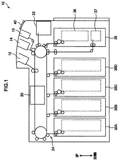
FIG. 1 is a schematic illustration of an image forming apparatus in an embodiment of the present invention.
In FIG. 2 , (a) to (d) are schematic views showing a filter frame in the embodiment, in which (a) is a plan view, (b) is a side view of the filter frame as seen from above the filter frame of (a), (c) is a side view of the filter frame as seen from a left side of the filter frame of (a), and (d) is a sectional view of the filter frame taken along A-A line of (a).
FIG. 3 is a perspective view of the filter frame in the embodiment.
FIG. 4 is a sectional view showing a state in which a first frame portion along B-B cross-section of (a) of FIG. 2 and a second frame portion along C-C cross-section of (a) of FIG. 2 are opposed to each other while sandwiching a filter therebetween.
In FIG. 5 , (a) to (c) are enlarged views, in which (a) shows a portion D of (d) of FIG. 2 , (b) shows a portion E of FIG. 4 , and (c) shows a portion F of (d) of FIG. 2 .
FIG. 6 is a sectional view of a filter assembly in the embodiment.
FIG. 7 is a perspective view showing the filter assembly in a state in which a gap-filling member is provided at an outer peripheral surface of the filter assembly.
FIG. 8 is a perspective view showing the filter assembly in a state in which the filter assembly is mounted to a duct of the image forming apparatus.
Description of the embodiments
An embodiment of the present invention will be described with reference to FIGS. 1 to 8 . First, using FIG. 1 , a general structure of an image forming apparatus in this embodiment will be described.
[Image Forming Apparatus]
In the image forming apparatus 100 , four photosensitive drums 10 a - 10 d for forming toner images of yellow, magenta, cyan and black, respectively, are provided. Further, at peripheral portions of these photosensitive drums 10 a - 10 d , unshown chargers, developing devices and cleaners are provided and are assembled into units as process cartridges 1 a - 1 d , respectively. On these process cartridges 1 a - 1 d , an intermediary transfer belt 2 as an intermediary transfer member is provided in contact with the photosensitive drums 10 a - 10 d.
The photosensitive drums 10 a - 10 c are electrically charged by the unshown chargers, respectively, and are exposed by an exposure device 6 to light with optical images, of yellow, magenta, cyan and black, respectively, which are color-separated on the basis of image information. Thus, latent images of yellow, magenta, cyan and black are formed on the photosensitive drums 10 a - 10 d , respectively. Then, the respective latent images are developed by the associated developing devices, so that toner images of yellow, magenta, cyan and black are formed on the photosensitive drums 10 a - 10 d , respectively.
With rotation of the photosensitive drums 10 a - 10 d , the toner images reach primary transfer positions where the photosensitive drums 10 a - 10 d contact the intermediary transfer belt 2 . The toner images are successively transferred onto the intermediary transfer belt 2 which is a moving image carrying member by primary transfer rollers 2 a - 2 d provided opposed to the photosensitive drums 10 a - 10 d , respectively. To each of the primary transfer rollers 2 a - 2 d , a primary transfer bias is applied from an electrical substrate described later.
A sheet (sheet material such as paper or an OHP state) P as a recording material accommodated in a sheet feeding cassette 4 is fed one by one by a pick-up roller 8 . Then, the sheet P is timed to the toner images by a registration roller pair 9 and thereafter is fed to a nip constituted by a secondary transfer 3 and the intermediary transfer belt 2 , where the toner images are collectively transferred from the intermediary transfer belt 2 onto the sheet P.
Thereafter, the sheet P on which the toner images are transferred is fed to a fixing device 5 , in which the respective color toners are melted and mixed under application of heat and pressure and then are fixed on the sheet P, so that a full-color print image is formed on the sheet P. The sheet P on which the toner images are fixed is discharged onto a discharge tray 7 by a discharging and feeding roller pair 21 provided downstream of the fixing device 5 with respect to a sheet feeding direction.
Arrangement of the above-described portions (members) in the image forming apparatus will be described. In the image forming apparatus 100 , from a bottom of an apparatus main assembly 20 , the feeding cassette 4 , the exposure device 6 , the process cartridges 1 a - 1 d , the intermediary transfer belt 2 , and the discharge tray 7 are provided in the listed order.
Incidentally, such an image forming apparatus 100 has multiple functions, and therefore, upsizing and speed-up of the image forming apparatus due to an increase in the number of constituent elements have progressed. Accordingly, in the apparatus main assembly 20 of the image forming apparatus 100 , there is an increase in the amount of electrical parts (components) constituting a heat source, and thus, a temperature increases in the apparatus main assembly 20 . For this reason, in order to suppress a temperature rise in the apparatus main assembly 20 , the air in the apparatus main assembly 20 is required to be discharged more efficiently.
Further, due to speed-up of a printing speed of the image forming apparatus 100 , vibration of the apparatus main assembly 20 becomes large, so that in addition to a contamination, due to an image forming process, such as toner powder raised in the air in the apparatus main assembly 20 , also dirt and dust in an operation (use) environment increase proportionally to a cooling air volume (amount). For this reason, a dust collecting filter provided to an air-discharging duct is required to have a higher dust collecting efficiency. Further, such a dust collecting filter is required to be exchanged periodically in order to maintain the dust collecting efficiency and a dust discharging efficiency. Therefore, it is required that shortening of a maintenance time, minimization of downtime and a reduction in running costs are achieved by improving a mounting property of such a filter and a maintenance property of an exchanging (replacing) operation or the like.
[Filter]
Next, a filter 31 ( FIG. 4 or the like) to be provided in an air-supplying or air-discharging path of the image forming apparatus 100 will be described. The filter 31 in this embodiment is a fibrous nonwoven fabric formed in a flat plate shape. The nonwoven fabric is prepared by assembling fibers in a sheet shape, and therefore, is weak is external force (strength) and is thus deformed. In the case where the filter 31 is used as an air filter, ease of passage of the air through the nonwoven fabric has a large influence on the air-discharging efficiency. On the other hand, the filter 31 is required to have a certain proper density so that dust articles which are an object to be collected are held in gaps of fibers of the nonwoven fabric. In the case where this density is unstable, the unstable density leads to unstable factors in terms of an air volume of a discharging fan, pressure loss of the filter 31 , a collecting efficiency, a lifetime of the filter 31 , and so on, and therefore has a large influence on the entirety of the image forming apparatus.
For this reason, the filter 31 is subjected to a special process for the purpose of preventing fraying of the fibers while maintaining a shape thereof. That is, a fixing method for preventing a change in position of the fibers by mutual shift of the fibers at a portion where the fibers microscopically constituting the nonwoven fabric contact each other is used. As the fixing method, for example, thermal bonding, chemical bonding, needle punching, stitch bonding, a water stream confounding method or the like may be used. In the thermal bonding, a heated air is blown to the fibers and thus contact portions of the fibers are welded to each other. In the chemical bonding, an adhesive is sprayed to the fibers and thus the fibers are bonded to each other. In the needle punching, a needle is moved at high speed and thus the fibers are confounded (entangled) with each other. In the stitch bonding, the fibers are stitched (sewed) by filaments which are long single fibers. In the water stream confounding method, the fibers are confounded by water pressure.
[Filter Frame]
Next, a filter frame 40 and a filter assembly 30 in this embodiment will be described using FIGS. 2 to 6 . The filter frame 40 is used for holding the filter 31 as described above, and constitutes the filter assembly 30 in a state in which the filter 31 is held in the filter frame 40 .
The filter frame 40 includes a first frame portion 41 and a second frame portion 51 as shown in (a) to (d) of FIG. 2 and FIG. 3 . As a material of the filter frame 40 constituted by the first frame portion 41 and the second frame portion 51 , a plastic (resin) material such as polypropylene or polyamide may suitably be used. In this embodiment, the first frame portion 41 and the second frame portion 51 are integrally formed using the plastic material.
Each of the first frame portion 41 and the second frame portion 51 is formed in a substantially rectangular shape. Further, peripheral four sides of the first frame portion 41 are constituted flat plate portions 42 a , 42 b , 42 c and 42 d , and peripheral four sides of the second frame portion 51 is constituted by flat plate portions 52 a , 52 b , 52 c and 52 d . The flat plate portions 42 a - 42 d of the first frame portion 41 and the flat plate portions 52 a - 52 d of the second frame portion 51 are disposed so as to surround spaces 43 and 53 , respectively. As shown in FIGS. 4 and 6 , these flat plate portions 42 a - 42 d and 52 a - 52 d are disposed so as to oppose each other in a state in which the second frame portion is folded up relative to the first frame portion 41 in order to sandwich the filter 31 between the first and second frame portions 41 and 51 .
At outer peripheral edge portions of the flat plate portions 42 a - 42 c , of the flat plate portions 42 a - 42 d of the first frame portion 41 , other than the flat plate portion 42 d connected with the second frame portion 41 as described later, wall portions 44 a - 44 c are provided to stand substantially vertically relative to the flat plate portions 42 a - 42 c , respectively. A direction in which the wall portions 44 a - 44 c are provided to stand in a direction in which the wall portions 44 a - 44 c face the second frame portion 51 in a state in which the second frame portion 51 is folded up relative to the first frame portion 41 (i.e., in a state in which the first frame portion 41 is combined with the second frame portion 51 so as to sandwich the filter 31 ). In a state in which the first frame portion 41 and the second frame portion 51 are superposed on each other, the wall portions 44 a - 44 c are positioned at a periphery of the flat plate portions 52 a , 52 b and 52 c of the second frame portion 51 . In other words, the outer peripheral edge portions of the flat plate portions 52 a , 52 b and 52 c of the second frame portion 51 are capable of entering an inside of inside surfaces of the wall portions 44 a - 44 c , respectively.
The first frame portion 41 and the second frame portion 51 are connected with each other by the flat plate portion 42 d as shown in (a), (c) and (d) of FIG. 2 and FIG. 3 . Further, the first frame portion 41 and the second frame portion 51 are rotatable relative to each other. Further, these portions are rotated so as to sandwich the filter 31 as shown in FIG. 4 , so that the filter 31 is sandwiched and held between the first frame portion 41 and the second frame portion 51 as shown in FIG. 6 . A detailed constitution of this portion will be described later.
[Projections]
As described above, each of the first frame portion 41 and the second frame portion 51 is formed in a substantially rectangular shape, and each of a plurality of first projections 45 a - 45 d and a plurality of second projections 55 a - 55 d is formed at peripheral edge portions in four sides. This will be specifically described below.
The first frame portion 41 includes the plurality of first projections 45 a - 45 d . The plurality of first projections 45 a - 45 d are arranged with intervals at edge portions in a region where the filter 31 is disposed and project toward the second frame portion 51 in a state in which the first frame portion 41 is combined with the second frame portion 51 so as to sandwich the filter 31 . That is, pluralities of first projections 45 a - 45 d are integrally formed so as to project from the flat plate portions 42 a - 42 d provided at the peripheral edges of the first frame portion 41 . Specifically, the flat plate portion 42 a is provided with the plurality of first projections 45 a linearly arranged with intervals along a longitudinal direction of the flat plate portion 42 a . Similarly, the flat plate portions 42 b , 42 c and 42 d are provided with the plurality of first projections 45 b , the plurality of first projections 45 c and the plurality of first projections 45 d , respectively, linearly arranged with intervals along longitudinal directions thereof, respectively.
The second frame portion 51 includes the plurality of second projections 55 a - 55 d . The plurality of second projections 55 a - 55 d are arranged with intervals at edge portions in a region where the filter 31 is disposed and project toward the second frame portion 41 in a state in which the second frame portion 51 is combined with the first frame portion 41 so as to sandwich the filter 31 . The plurality of second projections 55 a - 55 d are positioned between the plurality of projections 45 a - 45 d with respect to arrangement directions. That is, pluralities of second projections 55 a - 55 d are integrally formed so as to project from the flat plate portions 52 a - 52 d provided at the peripheral edges of the second frame portion 51 . Specifically, the flat plate portion 52 a is provided with the plurality of second projections 55 a linearly arranged with intervals along a longitudinal direction of the flat plate portion 52 a . Similarly, the flat plate portions 52 b , 52 c and 52 d are provided with the plurality of second projections 55 b , the plurality of second projections 55 c and the plurality of second projections 55 d , respectively, linearly arranged with intervals along longitudinal directions thereof, respectively.
For this reason, first gaps (intervals) 46 a - 46 d are formed between the pluralities of first projections 45 a - 45 , respectively, and second gaps (intervals) 56 a - 56 d are formed between the pluralities of second projections 55 a - 55 d , respectively. Further, in a state in which the first frame portion 41 and the second frame portion 51 are combined with each other so as to sandwich the filter 31 , the pluralities of first projections 45 a - 45 d and the pluralities of second projections 55 a - 55 d are positioned in the second gaps 56 a - 56 d and the first gaps 46 a - 46 d , respectively. As a result, the pluralities of second projections 55 a - 55 d are positioned between the pluralities of first projections 45 a - 45 d , respectively. Further, the pluralities of first projections 45 a - 45 d and the pluralities of second projections 55 a - 55 d are alternately disposed with respect to the arrangement direction in a state in which the first frame portion 41 and the second frame portion 51 are combined so as to sandwich the filter 31 .
Incidentally, as described later, at portions where engaging claws 47 a , 47 b and 47 c provided on the wall portions 44 a , 44 b and 44 c , respectively, of the first frame portion 41 are provided, the pluralities of first projections 45 a , 45 b and 45 c are not provided. Further, at these portions, gaps (intervals) larger than the first gaps 46 a , 46 b and 46 c , respectively, are provided. Further, in these gaps, the pluralities of second projections 55 a - 55 d are positioned, respectively, but the pluralities of second projections 55 a - 55 d positioned in these gaps and the pluralities of first projections 45 a - 45 d are not alternately disposed. However, at such portions, the first projections may also be provided so that they are alternately disposed with the second projections. In this embodiment, the pluralities of first projections 45 a - 45 d and the pluralities of second projections 55 a - 55 d may only be required so that the first projections and the second projections are alternately disposed at positions, with respect to the arrangement direction, other than one of a plurality of positions where they are not alternately disposed.
The pluralities of first projections 45 a - 45 d and the pluralities of second projections 55 a - 55 d are, as shown in (b) to (d) of FIG. 2 , FIG. 3 and FIG. 4 , formed so that both side surfaces of each of the pluralities of first and second projections approach an associated side surface toward its free end. That is, each projection is formed in a substantially triangular shape. At least a free end portion of each projection of the pluralities of first and second projections 45 a - 45 d and 55 a - 55 d is formed so that a thickness with respect to a widthwise direction perpendicular to the arrangement direction narrows toward its free end. In other words, outside and inside side surfaces of the first frame portion 41 and the second frame portion 51 approach each other toward free ends. In addition, with respect to the widthwise direction perpendicular to the arrangement direction, the side surface positioned in the outside of the filter frame 40 has an angle, relative to a projection direction of the free end portion, smaller than the side surface positioned in the inside of the filter frame 40 . In other words, the angle of the outside side surface relative to the projection direction is smaller than the angle of the inside side surface relative to the projection direction. These pluralities of first projections 45 a - 45 d and pluralities of second projections 55 a - 55 d have substantially the same shape. For this reason, as a representative, the first projection 45 c will be described using (a) of FIG. 5 . Incidentally, the outside of the first frame portion 41 refers to an outside relative to the space 43 , and the inside of the first frame portion 41 refers to a space 43 side. Further, the outside of the second frame portion 51 refers to an outside relative to the space 53 , and the inside of the second frame portion 51 refers to a space 53 side.
Each first projection 45 c is constituted by a base portion 61 and a free end portion 62 . The base portion 61 is formed integrally with the flat plate portion 42 c , and an interval between the outside and inside side surfaces is substantially the same. The free end portion 62 is a portion extended further in the projection position relative to the base portion 61 and is inclined so that an inside side surface 62 a approaches an outside side surface 62 b with a position closer to the free end of the projection 45 c . In this embodiment, the outside side surface is a surface substantially perpendicular to the flat plate portion 42 c along the side surface in the outside of the base portion 61 . On the other hand, the inside side surface 62 a is a gently inclined surface which inclines toward the inside of the projection 45 c from the side surface on the inside of the base portion 61 toward the free end of the projection 45 c . Accordingly, the angle of the outside side surface 62 b with respect to the projection direction is smaller than the angle of the inside side surface 62 a with respect to the projection direction. In other words, the inside side surface 62 a is inclined relative to the projection direction in a degree larger than the outside side surface 62 b.
[Hinge Portion]
Next, a hinge portion 48 for rotatably fixing the first frame portion 41 and the second frame portion 51 will be described. The hinge portion 48 rotatably fixes the flat plate portion 42 d which is a part of the first frame portion 41 to the flat plate portion 52 d which is a part of the second frame portion 51 . As described above, the first frame portion 41 and the second frame portion 51 are integrally formed using the plastic (resin) material. Further, as specifically shown in (c) of FIG. 5 , a portion connecting the first frame portion 41 and the second frame portion is formed in a small thickness so as to have flexibility, so that this portion is the hinge portion 48 .
[Holding Structure]
A holding structure for holding the first frame portion 41 and the second frame portion 51 in a superposed state will be described. In this embodiment, as shown in (a) of FIG. 2 and FIG. 3 , the first frame portion 41 is provided with the engaging claws 47 a - 47 c and the second frame portion 51 is provided with cut-away portions 57 a - 57 c as engaging portions with which the engaging claws 47 a - 47 c are engageable, respectively. A single engaging claw 47 a and a single engaging claw 47 b are formed on the wall portions 44 a and 44 b , respectively, of the first frame portion 41 so that each engaging claw projects from a free end toward the inside of an associated wall portion at a longitudinal central portion of the wall portion. Two engaging claws 47 c are formed on the wall portion 44 c of the first frame portion 41 so as to project from a free end toward the inside of the wall portion 44 c at two positions sandwiching a longitudinal central portion of the wall portion 44 c.
The portions of the engaging claws 47 a , 47 b and 47 c of the wall portions 44 a , 44 b and 44 c are formed so as to become thin toward a base end as shown in FIGS. 3 and 4 . As a result, when the engaging claws 47 a , 47 b and 47 c are engaged with or disengaged from the cut-away portions 57 a , 57 b and 57 c , respectively, an operation of engagement and disengagement between these portions is facilitated by elastically deforming the thin portions. Further, at positions of the flat plate portions 42 a , 42 b and 42 c opposing the engaging claws 47 a , 47 b and 47 c , respectively, through holes 49 a , 49 b and 49 c are formed, respectively, so that as described later, when the engaging claws 47 a , 47 b and 47 c are formed using metal molds, the metal molds are disengaged through the through holes 49 a , 49 b and 49 c.
As described above, the two engaging claws 47 a and 47 b are at least provided at two side peripheral edge portions, respectively, each continuous to an associated one of both ends of a one side peripheral edge portion where the hinge portion 48 is formed. That is, the two engaging claws 47 a and 47 b are provided on the wall portions 44 a and 44 b , respectively, of the flat plate portions 42 a and 42 b continuous to both ends of the flat plate portion 42 d where the hinge portion 48 is formed. In this embodiment, as shown in (a) of FIG. 2 and FIG. 3 , a connecting portion 70 for connecting the flat plate portions 42 a and 42 b so as to connect the portions where the engaging claws 47 a and 47 b of the flat plate portions 42 a and 42 b are provided. As a result, as described later, when the second frame portion 51 is opened relative to the first frame portion 41 in order to remove (demount) the filter 31 , the engaging claws 47 a and 47 b are easily disengaged from the cut-away portions 57 a and 57 b , described below, in interrelation with each other via the connecting portion 70 .
The cut-away portions 57 a and 57 b are formed in positions where the cut-away portions 57 a and 57 b engage with the engaging claws 47 a and 47 b , respectively, in a state in which the first frame portion 41 and the second frame portion 51 are superposed on each other. The cut-away portions 57 a and 57 b are formed so as to cut away parts of back surfaces of the flat plate portions 52 a and 52 b , as shown in FIG. 4 and (b) of FIG. 5 . That is, the two cut-away portions 57 a and 57 b are formed so as to cut away the surfaces (back surfaces), opposite from the second projections 55 a and 55 b , from longitudinal central edge portions of the flat plate portions 52 a and 52 b of the second frame portion 51 . The two cut-away portions 57 c are formed at positions where the two cut-away portions 57 c engage with the two engaging claws 47 c in the state in which the first frame portion 41 and the second frame portion 51 are superposed on each other. Theses cut-away portions 57 c are formed so as to cut away surfaces (back surfaces), opposite from the second projections 55 c , from two longitudinal central edge portions of the flat plate portion 52 c . The shape of the cut-away portions 57 c is the same as those of the cut-away portions 57 a and 57 b.
Incidentally, in the above-described explanation, the engaging claws are formed on the first frame portion 41 and the cut-away portions as engaging portions are formed on the second frame portion 51 , but the engaging claws may also be formed on the second frame portion 51 and the engaging portions may also be formed on the first frame portion 41 . Or, the engaging claws and the cut-away portions may also be formed on each of the first and second frame portions. That is, it is only required that of the first frame portion 41 and the second frame portion 51 , at least one of these frame portions is provided with the engaging claws and the other frame portion (and/or the one frame portion) is provided with the engaging portions.
[Holding of Filter]
Next, an operation for sandwiching and holding the filter 31 by the filter frame 40 having the above-described constitution will be described. First, in a state in which the filter 31 is sandwiched, the first frame portion 41 and the second frame portion 51 are rotated about the hinge portion 48 , so that the first frame portion 41 and the second frame portion 51 are moved near to each other as shown by two opposing arrows in FIG. 4 . Then, the peripheral edge portion of the filter 31 is sandwiched between the first and second frame portions 41 and 51 so that the filter 31 is accommodated inside the wall portions 44 a - 44 d of the first frame portion 41 and so that the filter 31 is sandwiched in the gaps of the pluralities of first projections 45 a - 45 d and the pluralities of second projections 55 a - 55 d while being pressed so as to become wavy.
Then, as shown in FIG. 6 , the first frame portion 41 and the second frame portion 51 are superposed on each other, so that the engaging claws 47 a - 47 c are engaged with the cut-away portions 57 a - 57 c , respectively. At this time, the engaging claws 47 a - 47 c are elastically deformed toward the outside while being engaged with the edge portions of the flat plate portions 52 a - 52 c , respectively, and then run over the edge portions and are elastically restored to original states, so that the engaging claws 47 a - 47 c are engaged with the cut-away portions 57 a - 57 c , respectively. As a result, during the engagement, the first frame portion 41 and the second frame portion 51 are connected to hold the filter 31 in a state in which the filter 31 is sandwiched therebetween. At this time, the first frame portion 41 and the second frame portion 51 are engaged with each other at peripheral edge portions other than the peripheral edge portion where the hinge portion 48 is formed, and therefore, a holding (retaining) force for holding (retaining) the filter 31 can be ensured. In this manner, the filter 31 is held in the sandwiched state by the filter frame 40 , so that the filter assembly 30 as shown in FIG. 7 is obtained.
In this embodiment, as shown in FIG. 7 , at outer peripheral surfaces of the first frame portion 41 and the second frame portion 51 in a state in which the filter 31 is sandwiched therebetween, i.e., at an outer peripheral surface of the filter frame 40 , a gap-filling member 71 as an elastic member is mounted. The gap-filling member 71 is formed in a substantially rectangular shape with a sponge and is bonded to the outer peripheral surface of the filter frame 40 , i.e., the outer peripheral surfaces of the wall portions 44 a - 44 c and the hinge portion 48 in the first frame portion 41 side, using a double-side adhesive tape or the like.
[Mounting of Filter Assembly]
Next, an operation for mounting the filter assembly 30 , constituted as described above, to an air-discharging duct 80 provided in the apparatus main assembly 20 of the image forming apparatus 100 as shown in FIG. 8 will be described. The air-discharging duct 80 is fixed to a side plate 22 of the apparatus main assembly 20 via a duct supporting plate 81 . Further, the air-discharging duct 80 is provided with a substantially rectangular filter case 82 , and the filter assembly 30 is disposed in the filter case 82 .
Specifically, as described above, in the state in which the filter 31 is held by the filter frame 40 , the gap-filling member 71 formed of a soft material such as sponge is mounted at a periphery of the filter frame 40 , so that the filter assembly 30 is prepared. In this state, the filter assembly 30 is engaged in the filter case 82 . As a result, a gap between the filter frame 40 and the filter case 82 is filled by the gap-filling member 71 , so that dirt and dust are prevented from leaking out through the gap.
[Exchange of Filter]
Next, an operation when the filter 31 , which collects the dust (dirt) by being provided and used in the air-discharging duct 80 and which is contaminated with the dust, is exchanged (replaced) will be described. When the filter 31 is exchanged, in reverse manner to the manner during the above-described mounting, the filter assembly 30 disposed inside the filter case 82 is demounted from the filter case 82 . Then, the filter frame 40 is opened, and the used filter 31 is taken out of the filter frame 40 . At this time, a force is applied to the filter frame 40 so as to flex (bend) the wall portions 44 a and 44 b of the first frame portion 41 without peeling the gap-filling member 71 . For example, of the wall portions 44 a and 44 b , the force is applied to the filter frame 40 so as to press the thin portions where the engaging claws 47 a and 47 b are formed or neighborhoods of the thin portions.
Here, as described above, the connecting portion 70 for connecting the flat plate portions 42 a and 42 b on which the wall portions 44 a and 44 b are provided, respectively, is provided so as to connect the portions where the engaging claws 47 a and 47 b are provided. For this reason, as described above, when the force is applied so as to flex (bend) the wall portions 44 a and 44 b , the wall portions 44 a and 44 b are flexed (bent) in a direction of spacing the engaging claws 47 a and 47 b from each other with the connecting portion 70 as a starting point. As a result, the engaging claws 47 a and 47 b are disengaged from the cut-away portions 57 a and 57 b , respectively.
Then, the second frame portion 51 is rotated with the hinge portion 48 as a starting point with respect to a direction in which the second frame portion 51 is opened relative to the first frame portion 41 . At this time, for example, the second frame portion 51 is rotationally raised in an open direction with fingers of an operator (user) and thus the flat plate portion 52 c is flexed (bent), so that the cut-away portion 57 c provided in the flat plate portion 52 c is inclined and thus the engaging claw 47 c engaging with the cut-away portion 57 c is raised. By further opening the second frame portion 51 , the engaging claw 47 c gradually runs over the cut-away portion 57 c , so that the engagement between the engaging claw 47 c and the cut-away portion 57 c is eliminated. As a result, the filter frame 40 is in an open state as shown in FIG. 3 .
Then, as described above, the used filter 31 is taken out of the filter frame 40 . Thereafter, a new (fresh) filter 31 is mounted in the filter frame 40 , and then the filter frame 40 is closed, so that the filter 31 is held in the filter frame 40 as described above. At this time, the gap-filling member 71 has been still mounted at the outer peripheral surface, i.e., the outer peripheral surfaces of the wall portions 44 a - 44 d and the hinge portion 48 . Thus, the filter assembly 30 in which the filter 31 is mounted again in the filter case 82 of the air-discharging duct 80 in the above-described manner.
As described above, in this embodiment, by flexing the first frame portion 41 , the engagement of the engaging claws 47 a and 47 b is eliminated in interrelation with the flexure of the first frame portion 41 , and by flexing the second frame portion 51 , the engaging claw 47 c is disengaged. For example, an operation such that the flat plate portion 52 c of the second frame portion 51 is pulled in a state in which the wall portions 44 a and 44 b of the first frame portion 41 are held by the second frame portion 51 so as to be sandwiched by the second frame portion 51 is performed. Then, each of the wall portions 44 a and 44 b and the flat plate portion 52 e is flexed, so that all of the engaging claws 47 a - 47 c are disengaged substantially at the same time. For this reason, there is no need to perform an operation for separately disengaging the engaging claws 47 a - 47 c , so that the contaminated filter 31 can be demounted and exchanged simply in a short time.
Further, in the case of this embodiment, the hinge portion 48 rotatably connecting the first frame portion 41 and the second frame portion 51 is constituted by thinning the connecting portion between the first frame portion 41 and the second frame portion 51 as shown in (c) of FIG. 5 . For this reason, when the filter 31 is exchanged or mounted, even when the first frame portion 41 and the second frame portion 51 are rotated, the hinge portion 48 does not interfere with the gap-filling member 71 . For this reason, it is possible to save the operator (user) the trouble of demounting and mounting the gap-filling member 71 during every exchanging or mounting operation of the filter 31 .
The description continues in the full USPTO document.
 Lapsed, fee not paid5 drawings