Technical field
The present invention generally relates to application medical drops and injections and, in particular, to a device effectuating recording of the use of a medication-filled container, housed in the device, during the delivery of such medication to a tissue to determine regimen compliance and the amount of medication delivered to the tissue.
Background
Patient's compliance with a prescribed therapeutic regimen can have a direct impact on the overall management of illness and clinical outcome, and, therefore, the improvements with regimen compliance will improve patient's health and reduce costs, both financial and physical associated with the therapeutic process. According to the data provided by the U.S. Department of Health and Human Services, diabetes affects over 25 million people in the US alone (National diabetes fact sheet: national estimates and general information on diabetes and prediabetes in the United States, 2011. Atlanta, Ga.: U.S. Department of Health and Human Services, Centers for Disease Control and Prevention, 2011), with, as estimated, 80 million people exhibiting signs of prediabetes. Though a strict adherence to diet, exercise, and drug regimens the diabetes sufferers can manage the symptoms associated with the disease indefinitely. Non-compliance to the insulin regimen is a significant problem for patients and health care professionals alike, and can exasperate the diabetes progression, with the unwanted results such as poor metabolic control, hospitalization for diabetes ketoacidosis, limb amputation, hyperosmolar coma, or even more detrimental consequences.
Because regimen compliance has been shown to be such a problem with patients and have such a significant impact on disease progression or presentation, many attempts have been made over the years to understand why patients have problems adhering to a regimen and how adherence can be improved. Furthermore, non-compliance to research study regimens significantly reduces the power and efficacy of clinical studies as an average compliance of 50% vs 100% requires an increase in sample size by fivefold to retain the sample study power. Thus having an accurate understanding of a patient's regimen compliance can help determine if a drug or therapeutic regimen is not working due to incorrect adherence or if an alternate regimen needs to be implemented by the physician. Unfortunately, understanding a patient's regimen compliance is difficult as patients often overestimate (incorrectly estimate) their adherence and multiple studies have found clinicians assessments of patient compliance to be unreliable.
Ideas for improving regimen compliance range from improving the doctor-patient relationship to improving patient oversight to improving patient health beliefs and providing education to patients regarding their disease. While each of these interventions has been studied, oversight is a major concern as over 95% of diabetic patients administering their own care, and regimen oversight has shown to significantly improve adherence. Accordingly, there remains a need for a system to document exactly how much medication delivered from a fluid filled container (for example, a syringe) actually gets into the delivery site (such as a patient's tissue), and according to which schedule such drug administration is carried out.
Eye-drop medications, both prescription and over-the-counter (OTC), are a mainstay of therapy for treating ocular complications. Eye drops are generally a preferred method of treatment because they are effective, substantially non-invasive, have limited systemic absorption and side effects compared to oral or intravenous medication administration, and in theory are easy to use. However, there is concern among ophthalmologists regarding the use of eye drops. Specifically, recent studies have found that compliance to eye-drop regimens is much lower than expected. This results in suboptimal therapeutic levels, which can reduce the efficacy of treatment. When eye drops are administered in a physician's clinic, trained technicians perform the procedure correctly; however, when eye drops are administered by patients (so called self-administration of treatment) they are not always administered correctly. The patient self-administering eye-drops does not always follow the procedural standards for drop administration and/or the proper timing for drop administration (for example for a twice a day regimen, the drops are not administered at 8 AM and 8 PM), which results in incorrect dosing. Even in cases where a clinician instructs a patient and/or asks a patient direct questions regarding an eye-drop regimen, or even when electronic monitoring of the procedure in employed, it is currently not possible to know if the drop intended for the eye actually got into the patient's eye or if they end up on the patients lid or if more than one drop was delivered into the eye. While some reasons for failed compliance are unavoidable, some of the causes (such as forgetfulness, confusion of similarly looking eye-drop containers or just plain error as to which eye drops to use, as well as failure to correctly follow an eye-drop administering procedure) are correctable.
Several devices have been developed to help patients adhere to eye-drop administering regimens. A system referred to as Travalert (manufactured by Alcon, Inc., Ft. Worth, Tex.), for example, utilizes electronic recording for unbiased, reliable measurements of instillation times and eye-drop counts. Other systems utilize timers and alarms to remind a patient that it is time to apply the eye drop(s) or weight measuring devices to ensure that medication has been removed from the bottle. Neither of these techniques for monitoring compliance with a procedure is meant to directly determine if and/or how much of the drop medication actually gets delivered to the patients eye(s). Instead, measurements performed by such systems are those of whether a patient attempts to administer the eye drops.
A study using video monitoring of eye-drop application has found that of subjects claiming not to miss an eye (when delivering eye-drops), nearly one third actually missed it and that out of all subjects using eye drops, approximately one third could not administer a drop onto the eye at all. Another study found that only about 9% of patients are able to correctly self-administer eye drops. Thus, even if patients are reminded about taking their eye drop medication and even if they have a scale for measuring dispensation of the eye drops, it is still not known if they drops ever make it into the eye or just land on the patients lids, cheek or other area outside the eye. It is also not known if the appropriate amount of medication finds its way into their eyes. Some patients waste copious amounts of eye drops trying to get the medication into their eyes and end up with too much or too little in their eye(s). Accordingly, there remains a need for a system to document exactly how much of a medication delivered from a fluid filled bottle, for example an eye-drop bottle, actually gets into the site it is to be delivered into, which for eye drops would be the patient's eye. There is also a need to a system that help patients understand how they are applying the drops, so that they can be educated on what changes need to be made to achieve the proper delivery of the drops/medication to their eye. Such a system should improve the management of ocular diseases, and should help to save health care costs by reducing the amount of drops wasted. In operation, for example, such a system provides an assessment of how much drug was delivered into the eye and provides an output based on which a better correlation can be defined of side effects (such as an irritation, for example, developed as a function of the volume of delivered drug) that a patient has from the drug to their application and application process. The system would allow for correlation of effects produced on an eye-lid as a function of a number of drops that get on the lid (instead of an eye) to better identify factors that lead to side effects and develop strategies for mitigation of such effects.
Summary
Embodiments of the invention provide a method for monitoring patient-performed drug delivery from a hand-held container to a region of interest (ROI) associated with the patient's body. Such method comprises (i) applying hand input to a drug-delivery system to squeeze a drop of the drug from a tip of the container and to release said drop from said tip, where the drug-delivery system includes (a) the container containing the drug and (b) a container-holding system having a first (optionally—size-adjustable) frame component structured to house (optionally—removably) the container therein along an axis thereof and a second frame component extending transversely with respect to the first frame component, the second frame component carrying an imaging camera having an optical field-of-view (FOV), an optical detector, and enabled to record images of a scene within the FOV; such that the FOV covers the tip, the ROI, and a space separating the tip from the ROI. The method further comprises (ii) recording a series of image frames, each frame representing a corresponding position of the drop in said space; and (iii) producing an identifier representing whether said drop landed in the ROI. Such identifier may be produced or formed as a conclusion based on an observation of the series of image frames. Alternatively or in addition, such identifier may be generated—for example, in an automatic fashion—based at least on a correlation figure of merit calculated in reference to an image frame and a template containing an image of the tip. The hand-held container may include a squeezable bottle and the ROI may include includes a patient's eye. The producing an identifier may include identifying a position of the tip that is common for all image frames from the series. The step of generating may include determining target image frames from the series, where target image frames represent only an advancement of said drop through said space. In a specific implementation, the producing an identifier includes generating an identifier representing whether said drop landed in the ROI based at least on a correlation figure of merit calculated according to
Cor ( x , y ) = .Math. i .Math. j [ T ( i , j ) - T _ ] [ F ( i + x , j + y ) - F _ ( x , y ) ] { .Math. i .Math. j [ T ( i .Math. j ) - T _ ] 2 .Math. .Math. i .Math. j [ F ( i + x , j + y ) - F _ ( x , y ) ] 2 } 1 / 2 , wherein T ( i , j ) is an irradiance value corresponding to a pixel of the template, F(i, j) is a pixel irradiance value of the image frame, T is an average of pixel irradiance values calculated over the template, and F (x, y) is a average of the pixel irradiance values of a local image area of the image frame.
The method may optionally include identifying a closed boundary of the ROI in a target image frame based on color segmentation of an image contained in said target image frame and, in addition or alternatively, determining a position of the drop relative to the ROI based at least on the FOV and a size of a pixel of the optical detector. The step of applying may include applying a hand input to a drug-delivery system to squeeze a drop of the drug from the tip of the container and to release said drop from said tip, wherein the second frame component includes a light source (whether visible or infrared) facing the scene, while the method may additionally contain a step of illuminating said drop with said light source for the recording of each image frame. In a specific embodiment, the recording a series of image frames can be effectuated in IR portion of the spectrum and in absence of a light source at the second frame component.
Embodiments of the invention also provide an article of manufacture that includes a mount dimensioned to (optionally removably) secure a chosen hand-held container having a tip, the mount having first and second frame components, the first frame component including first and second ends and length (that is optionally telescopically adjustable) along the fluid container, the second frame component connected to the first frame component at an angle, the second frame component carrying (i) a lens with a field-of-view (FOV) that covers a vicinity of the tip once the fluid container is secured in the mount and (ii) an optical detector. The optical detector is operable to detect visible light and/or IR light. Such mount further includes a source of light (visible and/or IR) disposed on the second frame component such as to illuminate an area in the vicinity; and electronic data-processing circuitry in operable communication with said optical detector and programmed to record and process the received optical data to determine temporal and spatial characteristics of the illuminated area. The optical detector is disposed in spatial coordination with the source of light to receive, from the lens, an irradiance distribution corresponding to light reflected by the area illuminated with the source of light. The angle may be adjustable, with a hinge operably connecting the first and second frame components, between about 0 degrees and 270 degrees. In a related embodiment, the angle may be fixed.
The mount may further include a ring-like adapter structured to ensure that the fluid container is removably secured in a portion associated with a neck of said fluid container; the adapter may be adjustable to accommodate fluid containers of variable sizes. An embodiment may additionally include a video-recording means in operable communication with the optical detector.
In a specific case, when the hand-held container includes a squeezable bottle filed with a drug to be delivered to a patient's eye and the bottle, in operation, is squeezed by the patient to form a drop of the drug at the tip and to effectuate such a delivery, (i) the area in the vicinity includes the tip, the patient's eye, and a space separating said tip and said eye, and (ii) the article additionally includes a tangible, non-transitory storage medium with program code stored thereon. Such code, when executed by the electronic data-processing circuitry, causes said circuitry to record a series of image frames, each frame representing a corresponding position of said drop in said space; and generate an identifier of said spatial and temporal characteristics based at least on a correlation figure of merit calculated in reference to an image frame and a template containing an image of the tip. The spatial and temporal characteristics of the area illuminated with the light source represent one or more of (i) a merit of success of delivery of the drug to the patient's eye, (ii) a first value associated with an amount of drug dispensed from the hand-held container, (iii) a second value representing time of drug delivery; and (iv) a third value representing a proportion of the first value delivered to the patient's eye. In one embodiment, the article may be further equipped with an infra-red heat detection optical system which can increase the differentiation between the medication and the tissue on imaging thus improving the ability to system to detect the eye drop and follow its path in some patients when compared to a visible light system.
In one embodiment, the images are then analyzed by image analysis software which will be able to partially or fully automatically detect when the drug administration occurred, whether or not a drug administration was applied correctly and exactly where and how much of the medication was dispensed. This software can be located on computer equipment that is separate from the image acquisition and image storage devices. The software can also be packaged in a processor in the proximity or as part of the image acquisition and storage devices, so as to give the patient prompt feedback on the success of the drop delivery. In one embodiment of the article, the regimen compliance analysis may be done by individuals in a secured reading center, which may compile data recorded by the article.
In one embodiment, the article may be powered by an internal battery. In another embodiment, the article may be powered via a corded connection with an external power source.
In one embodiment, the article may transfer captured images wirelessly or via a wired connection.
Brief description of the drawings
The invention is more fully understood by referring to the following Detailed Description in conjunction with the generally not-to-scale Drawings, of which:
FIGS. 1A, 1B, 2, 3, 5A , provide illustrations to an embodiment of the invention in which the frame elements are repositionably attached to one another via a hinge;
FIGS. 4A, 4B, 5B illustrate an embodiment of the invention in which the frame elements are affixed to one another in a permanent spatial configuration. FIG. 4A illustrates the exploded view of the embodiment, while FIG. 5B shows an external device operably wired to the embodiment.
FIGS. 6A, 6B, 6C, 6D are images representing video-frames acquired with an embodiment of the invention during the eye-drop delivery procedure;
FIGS. 7 and 8 are diagram showing the use of an alternative embodiment of the invention, that contains and supports an injection unit;
FIGS. 9A, 9B are diagrams showing the alternative embodiment of FIGS. 7 and 8 ;
FIGS. 10A, 10B, 10C, 10D illustrate schematically various components of the embodiment of FIGS. 7 and 8 ;
FIG. 11 is a diagram illustrating an optionally spatially-expandable component of the embodiments of FIGS. 1A, 1B, 2, 3, 4A, 4B, 5A, 5B, 7, and 8 .
FIGS. 12A, 12B are additional illustrations of the embodiment of FIGS. 7, 8 .
FIG. 13 is a flow-chart of an algorithm of the invention;
FIG. 14 is a gray image acquired during the eye-drop delivery procedure with an embodiments of the invention and illustration a position of the nozzle, of a drop-container fixed in the embodiment, with respect to the field-of-view of the camera of the embodiment;
FIG. 15 is a plot showing a change in a position of eye-drop(s) as a function of a image/video-frame number;
FIGS. 16A, 16B are images illustrating, respectively, a step of color segmentation of an image-frame and the resulting image with an area of the eye identified according to an embodiment of the invention;
FIG. 17 is a compilation of several video-frames with over-imposed markers showing the trajectory of an eye-drop from the nozzle of the drop-container towards the eye.
Detailed description
Embodiments of the present invention provide a medication adherence intervention device for chronic health conditions such as Glaucoma and Diabetes. This device is structured to enable physicians to have a direct and impartial understanding of a patient's drug regimen adherence so as to allow for discrete intervention to improve drug delivery and/or compliance so as to prevent disease progression. Each instance of drug application is recorded by a portable imaging device. The images can then be reviewed by the patient, their physician, a reading center, and/or imaging software. A report can then be generated, allowing the patient and/or his physician, physician's staff or such other health care entities or people that might participate or assist in the patients care to intervene when necessary to improve therapeutic regimen delivery to the tissue or eye and/or compliance and thus improve patient health and disease management. One embodiment of the device has been designed to fit standard insulin syringes without interfering with the injection procedure to monitor diabetes management or to fit a standard eye drop bottle for monitoring of glaucoma drug administration. As such, the device is superior to current monitoring methods such as MEMS caps, pharmacy refill records, and pill counts as it will allow for direct visualization of drug administration rather than rely on indirect monitoring methods which may not be indicative of actual regimen compliance.
Embodiments of the present invention address the need for knowing if a medication delivered in a fluid filled syringe or drop bottle actually arrives to the site it is intended to be delivered to, and gives the potential to automate the drug delivery assessment. According to the idea of the invention, and instead of relying on indirect compliance measurements (for example, weighing drug container and/or timers/alarms), an embodiment of a system of the invention employs a video-monitoring means in juxtaposition with the fluid-filled container to record the actual administration of fluid to the tissue, which can be reviewed and quantified. In addition, the recorded images can be time-stamped to provide a record of the exact time of administration. The data acquired and, optionally, recorded by a device of the invention can be further transferred and/or stored on a tangible computer-readable medium, for example, for visual display and/or visual and digital assessment of compliance with the procedure. Such data can then be transferred to a remote server or reading center, where it can be reviewed manually or automatically, and a written report detailing actual drug delivery to the tissue as well as the timing of the delivery can be provided to the physician and/or patient. Additionally, these data can be further analyzed and a summary report can be provided which includes average and/or median variance(s) from a prescribed dosing time, as well average and/or median variances in the amount of the drug delivered to the tissue as well. Statistical data, such as standard deviation and such other statistical analysis as may be found useful can also be provided. All of this assessment may be done by the reading center and/or by the image analysis software included in the device.
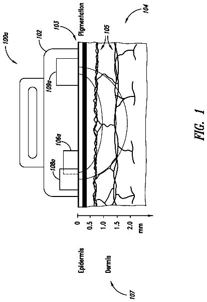
In reference to the drawings, FIGS. 1A, 1B, 2, 3, 4A, 4B, 5A, 5B provide diagrams illustrating schematically different views of the components of a monitoring system for eye drop administration as well as the monitoring system in the assembled form. The embodiments 100 , 500 are referred to as Eye-Drop Application Monitor (EDAM) and are shown in cooperation with a container 110 filled with eye drops and having a nozzle 110 a that is covered, when not in operation, with a cap 110 b . The embodiment 100 includes a first frame element or arm 101 configured, as discussed below, to accommodate the container 110 , and a second frame element 102 affixed to the first frame element 101 . In one implementation 100 , the second frame element 102 is adjustably and/or repositionably connected to the first component 101 with a hinge 103 . The second frame component 102 is generally disposed at an angle α with respect to the first frame component 101 . This angle α can range from about 60 to about 200 degrees, preferably from about 90 to about 170, and even more preferably from about 120 to about 150 degrees. In a specific implementation, the angle α is about 135° to facilitate an optimal viewing of the eye drop procedure by a camera of the embodiment, as detailed below. (Alternatively, the second frame element 102 may be fixedly connected to the first frame element 101 at an angle β, as shown in FIG. 4A, 4B , with β being within a range from about 60 to about 200 degrees, preferably from about 90 to about 170, and even more preferably from about 120 to about 150 degrees. In a specific implementation, the angle β is about 135° to facilitate an optimal viewing of the eye drop procedure by a camera of the embodiment, as detailed below.) The position of the video camera and lens are generally such that the tip of the drop bottle is within the field of view of the video image, more preferably no more than 50% into the image, and most preferably extending around 25% into the video frame.
In further reference to FIGS. 1A, 1B, 2, 3, 4A, 4B, 5A, 5B , the first frame element 101 includes a portion 111 with the first and second ends that are configured as the foot portion 109 and a clasp 112 . The first frame element 101 optionally has an adjustable length that can be changes from inside the portion 111 (for example, telescopically, and optionally under a load such as a spring load, by repositioning one sub-portion 111 A of the portion 111 inside another sub-portion 111 B) to allow for insertion of a fluid containing bottle of different lengths or heights. The foot portion 109 is shaped to provide contact, on one side of the base portion 109 , with a bottom of the fluid-filled container 110 such as to spatially stabilize (optionally—tensionably under the load of the spring within the telescopic portion 111 ) the container in the first frame element 101 between the foot 109 and the clasp 112 . As shown in FIG. 4B , one of the sub-portions 111 A, 111 B can be optionally equipped with a mounting arm brace 430 dimensioned to support the sub-portion 111 A when the portion 111 of the first frame element 101 A is in a fully contracted state.
The embodiment of the device may be additionally optionally equipped with a base unit 104 , configured as a holder for a power unit (such as an optionally replaceable and/or rechargeable battery) and/or auxiliary hardware (such as electronic circuitry and/or programmable processor and/or tangible storage medium) required for operation of the embodiment 100 . In a related embodiment, however (such as that of 500 , FIG. 5 ), the base unit 104 may be absent at least one of the power unit and the auxiliary hardware elements may be disposed within or in juxtaposition with the frame element or arm 101 . Optionally, the base unit 104 is equipped with a port 105 adapted for operable connection with a computer or another external electronic device (not shown) in a fashion similar to that of an USB port, for example, or an electrical plug. The port 105 is judiciously configured for transfer of data and/or power between an external device and the base unit 104 (for example, to recharge a battery within the base unit 104 or to transfer the data collected by the system 100 to the external electronic device). In a related implementation, the port 105 is adapted to facilitate spatial docking of the system 100 at an external electronic platform (not shown). Such docking platform can allow for charging and data transfer, weighting or such other functions as are found to be beneficial. In an embodiment optionally devoid of base unit 104 , the operable, data- and energy-transfer enabled connection between the camera 106 and the external battery and/or data storage medium and/or data-processing circuitry 550 may be configured either through a direct wire-based connection 560 or wirelessly (with the use of Bluetooth, intranet, or internet based communication means), as shown in FIG. 5B . This would allow for the battery and image/video recording software to be housed in a separate unit that could be placed on a table or in one's lap during use of the device.
In further reference to FIGS. 1A, 1B, 2, 3, 4A, 4B, 5A, 5B the second frame component 102 (shown as a handle, optionally movable angularly about the hinge 103 ) carries, on its surface that faces the clasp 112 , a camera 106 that is optionally equipped with a micro-optical system including a lens. The frame component 102 additionally carries at least one light source 107 , the light from which provides required illumination of a scene an image of which the camera 106 is enabled to capture. The affixation of the camera 106 at the frame component 102 can be established with the use of an appropriate adhesive or an alternative mounting means know in the art (such as with the use of a threaded indentation or bore formed in the body of the component 102 ). The light source(s) 107 may include an LED, a halogen bulb, or another source of light having appropriate dimensions. The light source(s) 107 may use light in the visible light 380 nm-700 nm) and the typical illumination intensity is approximately 250 millicandelas (mcd), though this can vary, depending on the wattage used for powering the light source(s). In all cases, it needs to be below levels which could cause light induced retinal toxicity. Based on current technology, the visible light illuminating light source(s) 107 require approximately 120 mW of power, provided by the electronic circuitry 410 . FIG. 3 illustrates cases in which the embodiments of the device include two light sources 107 . When several light sources 107 are disposed at the second frame component 102 , such light sources 107 may be spatially distributed around the camera 106 in a pre-determined geometric fashion (for instance, circular, or polygonal depending on the number of the light sources 107 ). The spatial positioning and/or orientation of the camera 106 and the light source(s) 107 is such that, in operation, when the eye-drop container is secured between the clasp 112 and the foot 109 , the illumination of the eye-drops emitted from a nozzle 110 a by the light source(s) 107 is sufficient to acquire informative images of the eye-drops from the time they leave the eye drop tip until they enter the eye or miss the eye. In one embodiment, the tip of the eye drop bottle is seen at the edge of the image, so that its direction can be recorded from the time it leaves the bottle until the time it contacts the tissue. Elements 414 , 418 annotate structural components used to support and house the camera unit 106 .
The camera 106 and/or the light source(s) 107 are electrically connected with the base unit 104 via an electrically-conductive member 108 . In one embodiment, such member 108 includes an electrical wire or bus passing through the hollow or the internal space in the slidably-adjustable portion 111 . In another embodiment (not shown) the electrically-conductive member 108 may be disposed outside of and substantially adjacent to the portion 111 or even embedded within the body/walls of the portion 111 .
An optional lens of the camera 106 preferably has a field of view of about 60 degrees to about 180 degrees (defined by a full linear angle). In one embodiment, for example, a wide angle lens with about 120 to about 180 degree field of view can be used, or, preferably, with the field of view from about 150 degrees to about 180 degrees. While any lens suitable for imaging at a distance of about 5 mm to about 50 mm between the eye and the lens are acceptable, generally a wide angle lens are preferred. In a related embodiment, the working distance between the camera 106 and the eye ranges, in operation, between about 5 mm to about 100 mm, more preferably between 10 mm and 50 mm, and most preferably 15 mm and 35 mm. Accordingly, the optional lens of the camera 106 has a focal length from about 0.2 mm to 4 mm, or more preferably from about 0.5 mm to about 2.54 mm, and most preferably from about 0.75 mm to about 1.5 mm. In practice, a lens' F-number may range from about 1 to about 5, or more preferably from about 1.5 to about 3. An image detector associated with the camera 106 (not shown, for example behind the camera 106 in the component 102 ) is configured for acquisition of optical data representing the scene including the vicinity of the nozzle 110 a (such as, for example, eye drops emitted by the nozzle 110 a and an eye of a patient to which these eye drops are directed). In general, a CMOS based detector with size ranging within the range of about ⅕″-½″ and pixel count in a range of 400*400 to 2048*2048 or higher as better detectors become available, preferably ⅓″, with a pixel count of about 1024*1024 or greater is used. Additionally, an embodiment of the monitoring system may contain a user-interface with a time-counting and/or sound- or light-emitting mechanism and/or wireless transmitter transmitting data to an external patient-readable to remind the patient that it is time for their next eye drop to be administered. The action of turning on the embodiment and administering another drop or depressing a relevant trigger of the user interface could then stop or re-set such notification reminder (which may be configured as light alert, email or text to the patient's phone, or sound alert, for example, to name just a few).
While the current design allows for use with multiple different sized fluid filled containers, it being understood other designs in which the unit is fixed to fit a single fluid filled container, and has some or no moving parts, may also be utilized. It being understood that fluid filled containers include eye drops, ear drops, nose drops, oral drops, dermal drops, syringes (as further discussed below), and any other such fluid filled containers as can be envisioned or used for delivery of medications in humans, and or animals. In the case where the drops are delivered from a fluid filled tube that is inserted into a fluid filled container, the camera can be affixed to the fluid filled tube.
The following examples of experimental studies illustrate the use of the eye-drop application video-monitoring device (such as that used in the embodiments 100 of FIGS. 1A, 1B, 2, 3, 4A, 4B, 5B and 500 of FIG. 5A ) in assessment of a patient's eye-drop medication regimen. This is particularly important for clinical studies of new medications being delivered by in the form of an eye drop, to allow the researcher to determine if a patient's failure to respond to a drop regiment is because the medication did not work or if it was because the patient did not take the medication at the prescribed time, or it did not get into their eye. If side effects occur, an embodiment of the invention also facilitates a determination of whether such effects resulted from overuse of the drops, or other problems with delivery which might not have happened if they had been delivered correctly. Finally, for eye-doctors treating patients for conditions such as glaucoma, it is important to know if the reason for a patient's lack of response is a failure of the medication to work, or due to incorrect dosing or such dosing in which a required number of eye-drop is not delivered into an eye, as such knowledge will affect the manner in which the doctors determines future therapy regimen(s). In the event of side effects, it will be possible to determine if they are a result of improper delivery, excess delivery or simply the medication itself. From this information a more accurate adjustment can be made to the patient's medication regimen. The required adjustment may be as simple as retraining the patient as to proper delivery of the drops to the eye, or a selection of another medication. In the event when the failure to achieve proper delivery of the drug is caused by arthritis, a tremor, inability to properly train, or other ailments alternative glaucoma therapies such as laser surgery (such as Selective Laser Trabeculoplasty (SLT), Argon Laser Trabeculoplasty (ALT), Micropulse Laser Trabeculoplasty (MLT), and Laser Cyclophotocoagulation)), incisional surgery (Trabeculectomy, Valve, Canalostomy, Seton surgeries) oral agents or some combination thereof may be prescribed and/or performed.
Accordingly, in one experiment, ten eye drops per subject, placed in the container 110 of the embodiment 100 , were dispensed in an eye, outside of the eye, and at the transitional region corresponding to at the edge of a lid and/or corner of the eye, multiple times. Video-recording was taken of the dispensing procedure, in addition to which an independent skilled eye-care provider/observer also documented a number of drops that, according to his observation, were delivered to the eye in comparison with a number of the eye drops that missed the eye. Processing of the video-recording with data-processing circuitry (such as a computer processor) established that in 100% of the video-images it was possible to determine with certainty whether a given drop was delivered into the eye. The comparison of the results with the individual observation is presented in Table 1. There exists variability in the actual results between what is recorded by video and what the skilled eye care provider observed. Due to the speed and/or rate with which the drop(s) enter the eye, the capacity of the eye to absorb the volume of delivered medication is often exceeded and, as a result, accuracy of visual determination of compliant delivery of the drop(s) to the eye by a patient or an observer is compromised. This is particularly true for drops that are used for dry eye or are non-preserved and do not cause pain and irritation when they are instilled, as it is harder to tell if they got into the eye. However, with the video record it is possible to tell with 100% certainty if the drop got into the eye.
TABLE-US-00001 TABLE 1 Experiment Video HumanObserver # In Out 50/50 Unsure In Out 50/50 Unsure #1 2 3 0 0 2 2 0 1 #2 2 3 0 0 2 2 0 1 #3 3 2 0 0 3 1 0 1 #4 3 2 0 0 3 2 0 0 #5 2 2 1 0 3 2 0 0 Example 2
An infrared incarnation of the camera (such as the camera 106 of the embodiment 100 and, in this specific experiment—the Atom 1024IR camera), was used to assess the quality of imaging and recordation of the eye-drop delivery to the target (the eye) With the use of such recording means it was possible to clearly see the drop which appeared black against the white back-drop of the skin of the patient. Here, in reference to FIGS. 6A, 6B, 6C, and 6D , the embodiment of the invention had a capability to detect temperature differences of less than 50 milliKelvin (mK), with the pixel a resolution of 1024×768 (17 micron pixels), a 30 Hz XGA or 60 Hz VGA frame rate, and a thermal time constant of less than 10 ms. The experiment was carried out in an air conditioned building at 78 degrees F., while the eye-drops were at a room temperature. A temperature flush could also be observed when a drop entered the eye, which returns to a normal temperature and restores its IR signature in seconds afterwards. In an alternative version of the experiment, eye-drops were refrigerated and similar eye-drop delivery into an eye and associated recording/monitoring produced similar results.
In addition or alternatively to the use of the monitoring-device structure discussed above in reference to FIGS. 1 through 6 , the idea of the invention may be used to visualize the injection of insulin or some other drug.
To this end, and in further reference to the drawings, FIGS. 7, 8, and 9A present different perspective views illustrating schematically an embodiment 700 of a monitoring system that includes a bracing element or bracer 704 (shown to contain two frame elements 704 A, 704 B repositionably affixed to one another about a pivotal point 706 ). In one implementation (and as shown), the two frame elements 704 A, 704 B of the bracer 704 have substantially similar structures and, as such, can be considered to be halves of the bracer 704 . Generally, however, the bracer frame elements 704 A, 704 B may be structurally different but are configured to fixatedly and tightly accommodate a drug-container disposed between them. The bracer 704 is preferably equipped with a fastening means 710 disposed at the facing each other ends of the bracer frame elements 704 A, 704 B to facilitate a fixed cooperation therebetween after the elements 704 A, 704 B are swung towards one another about the pivotal point 706 . FIGS. 7 and 8 illustrate the embodiment 700 in juxtaposition with a syringe 714 having a needle 716 and a plunger 718 and filled with liquid (fluid) drug, while FIG. 9A is a view of the embodiment 700 by itself, with the bracer frame elements 704 A, 704 B hingedly open about an axis passing through the pivotal point 706 . In a specific implementation of the invention the cooperation between the frame elements 704 A, 704 B may be, optionally, completely detachable, in which case a second fastening means (not shown) is used in place of the hinge about the pivotal point 706 .
The description continues in the full USPTO document.
 Lapsed, fee not paid69 drawings