 Lapsed, fee not paid8 drawings
Cameras, Displays & Optics · US 9,838,629 B2
Pixel array and method for controlling a pixel array
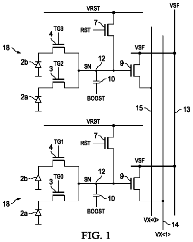
A pixel array includes pixels arranged in columns.
US 9,838,637 B2 · Assignee: Canon Kabushiki Kaisha · Inventors: Muto; Takashi et al.
Sheet 1 of 16 from the published document. All sheets in the USPTO PDF
A solid-state image sensor includes a pixel configured to generate a pixel signal corresponding to incident light, an amplification circuit configured to amplify the pixel signal, a setting circuit configured to set a gain of the amplification circuit based on a comparison result between a threshold and the pixel signal amplified by the amplification circuit, and a correction circuit configured to correct the pixel signal, which is amplified by a gain set by the setting circuit, by using a first correction value and a second correction value. The first correction value is a value corresponding to a gain error and the second correction value is a value corresponding to an offset of the amplification circuit in the gain.
Field of the Invention The present invention relates to a solid-state image sensor, a method of controlling the same, an image sensing system, and a camera. Description of the Related Art There is known a solid-state image sensor that applies a plurality of gains to one pixel signal generated by a pixel in order to implement a wide dynamic range or a high-speed readout. Japanese Patent Laid-Open No. 2005-175517 and Japanese Patent Laid-Open No. 2014-131147 each disclose a method of amplifying a pixel signal, which is obtained by amplifying the pixel signal by a given gain, by another gain in accordance with the level of the obtained signal. The amplified pixel signal is converted into a digital signal by an A/D converter. This digital signal is divided by a value corresponding to the gain used to amplify the pixel signal, and a gain difference corrected pixel value is obtained.
1 of 16 drawing sheets so far from the published document, cropped to the drawing. Every sheet is in the USPTO PDF.
What the patent claimed, word for word. All of it is now free to use.
Field of the Invention
The present invention relates to a solid-state image sensor, a method of controlling the same, an image sensing system, and a camera.
Description of the Related Art
There is known a solid-state image sensor that applies a plurality of gains to one pixel signal generated by a pixel in order to implement a wide dynamic range or a high-speed readout. Japanese Patent Laid-Open No. 2005-175517 and Japanese Patent Laid-Open No. 2014-131147 each disclose a method of amplifying a pixel signal, which is obtained by amplifying the pixel signal by a given gain, by another gain in accordance with the level of the obtained signal. The amplified pixel signal is converted into a digital signal by an A/D converter. This digital signal is divided by a value corresponding to the gain used to amplify the pixel signal, and a gain difference corrected pixel value is obtained.
As will be described later, a generated pixel value may not have a good linearity just by dividing an amplified digital signal by a value corresponding to a gain. An aspect of the present invention is to provide a technique of generating a pixel value that has good linearity in a solid-state image sensor which can switch the gain of an amplification circuit that amplifies a pixel signal.
According to some embodiments, a solid-state image sensor includes a pixel configured to generate a pixel signal corresponding to incident light, an amplification circuit configured to amplify the pixel signal, a setting circuit configured to set a gain of the amplification circuit based on a comparison result between a threshold and the pixel signal amplified by the amplification circuit, and a correction circuit configured to correct the pixel signal, which is amplified by a gain set by the setting circuit, by using a first correction value and a second correction value, the first correction value being a value corresponding to a gain error and the second correction value being a value corresponding to an offset of the amplification circuit in the gain.
Further features of the present invention will become apparent from the following description of exemplary embodiments (with reference to the attached drawings).
FIG. 1 is a block diagram for explaining an example of the arrangement of a solid-state image sensor according to a first embodiment;
FIGS. 2A to 2C are diagrams for explaining examples of the respective circuit arrangements in the solid-state image sensor of FIG. 1 ;
FIG. 3 is a timing chart for explaining an image signal reading operation of the solid-state image sensor of FIG. 1 ;
FIG. 4 is a graph for explaining a pixel value correction operation of the solid-state image sensor of FIG. 1 ;
FIG. 5 is a timing chart for explaining a correction value calculation operation of the solid-state image sensor of FIG. 1 ;
FIG. 6 is a diagram for explaining an example of the circuit arrangement of a first modification of the solid-state image sensor of FIG. 1 ;
FIG. 7 is a timing chart for explaining a pixel signal reading operation of the first modification of the solid-state image sensor of FIG. 1 ;
FIG. 8 is a block diagram for explaining an example of the arrangement of a second modification of the solid-state image sensor of FIG. 1 ;
FIG. 9 is a diagram for explaining an example of the circuit arrangement of a second modification of the solid-state image sensor of FIG. 1 ;
FIG. 10 is a timing chart for explaining a pixel signal reading operation of the second modification of the solid-state image sensor of FIG. 1 ;
FIG. 11 is a block diagram for explaining an example of the circuit arrangement of a third modification of the solid-state image sensor of FIG. 1 ;
FIG. 12 is a block diagram for explaining an example of the arrangement of a solid-state image sensor according to a second embodiment;
FIG. 13 is a diagram for explaining an example of the circuit arrangement of the solid state image sensor of FIG. 12 ;
FIG. 14 is a graph for explaining a pixel value correction operation of the solid-state image sensor of FIG. 12 ;
FIG. 15 is a timing chart for explaining a correction value calculation operation of the solid-state image sensor of FIG. 12 ; and
FIG. 16 is a view for explaining an example of the arrangement of an image sensing system according to a third embodiment.
Embodiments of the present invention will be described below with reference to the accompanying drawings. The same reference numerals will denote the same elements throughout the various embodiments, and a repetitive description thereof will be omitted. The embodiments can be changed and combined as needed. First Embodiment
The arrangement of a solid-state image sensor IM 1 according to the first embodiment will be described with reference to the circuit block diagram of FIG. 1 . The solid-state image sensor IM 1 includes the components shown in FIG. 1 . A pixel array 101 is formed by a plurality of pixels 100 arranged in a matrix. A case in which the pixel array 101 includes 4 rows and 3 columns of pixels 100 will be described as an example in FIG. 1 . However, the arrangement of the pixel array 101 is not limited to this. A pixel signal is generated in each pixel 100 in correspondence with incident light to the pixel 100 . The plurality of pixels 100 forming the same row are commonly connected to a single driving line. A control signal for controlling the operation of each pixel 100 is supplied from a vertical scanning circuit 103 to the pixel 100 via the driving line. The plurality of pixels 100 forming the same column are also commonly connected to a single vertical line 102 . A voltage signal supplied to each amplification circuit 104 via the corresponding vertical line 102 is called a vertical line signal Vvl. When a pixel signal is read out from each pixel 100 to the vertical line 102 , the vertical line signal Vvl changes to a value corresponding to the pixel signal.
Each amplification circuit 104 generates an amplified signal Vamp by amplifying the vertical line signal Vvl and supplies the amplified signal Vamp to a corresponding setting circuit 105 and a corresponding comparison circuit 107 . The amplification circuit 104 generates the amplified signal Vamp by amplifying the vertical line signal Vvl by one of the plurality of gains (to be described later). The amplification circuit 104 amplifies the pixel signal when the vertical line signal Vvl is a value according to the pixel signal.
Each setting circuit 105 compares the amplified signal Vamp with a predetermined threshold voltage Vsh and sets the gain of the corresponding amplification circuit 104 based on the comparison result. The setting circuit 105 supplies a setting signal ATT which indicates the gain setting of the amplification circuit 104 to the amplification circuit 104 and a corresponding memory unit 109 . As an example, each setting circuit 105 of this embodiment sets the setting signal ATT to L level if the amplified signal Vamp is smaller than the threshold voltage Vsh and sets the setting signal ATT to H level of the amplified signal Vamp is larger than the threshold voltage Vsh. The amplification circuit 104 maintains or changes the gain used for amplifying the vertical line signal Vvl in accordance with the level of the setting signal ATT. That is, the setting circuit 105 determines whether the gain of the amplification circuit 104 should be changed. The gain is changed while the amplification circuit 104 is amplifying the pixel signal.
Other than the amplified signal Vamp from the amplification circuit 104 , a reference signal Vr is supplied from the reference signal generation circuit 106 to each comparison circuit 107 . The reference signal generation circuit 106 outputs a ramp signal as the reference signal Vr according to an instruction from a control circuit 113 . The ramp signal is a signal that changes at a predetermined ratio with the elapsed time. The comparison circuit 107 compares the amplified signal Vamp and the reference signal Vr and supplies, to the corresponding memory unit 109 , a comparison signal Vcmp corresponding to the comparison result. As an example, each comparison circuit 107 of this embodiment sets the comparison signal Vcmp to L level if the amplified signal Vamp is larger than the reference signal Vr and sets the comparison signal Vcmp to H level if the amplified signal Vamp is smaller than the reference signal Vr. For example, a comparator is used as the comparison circuit 107 .
Other than the setting signal ATT from the corresponding setting circuit 105 and the comparison signal Vcmp from the corresponding comparison circuit 107 , a count signal CNT is supplied from a counter 108 to each memory unit 109 . In accordance with an instruction from the control circuit 113 , the counter 108 starts counting together with start of ramp signal supply by the reference signal generation circuit 106 and counts up the count values expressed by the count signals CNT along with the lapse of time. Each memory unit 109 includes a memory 109 S, a memory 109 N, and a memory 109 D. The memory 109 D holds the level of the setting signal ATT supplied from the corresponding setting circuit 105 . Each of the memories 109 S and 109 N holds a count value at the point when the level of the comparison signal Vcmp has switched. That is, the reference signal generation circuit 106 , the comparison circuit 107 , the counter 108 , and the memory unit 109 form an A/D conversion circuit that converts the amplified signal Vamp into a digital value. The memory 109 N holds a digital value corresponding to the amplified signal Vamp output by the amplification circuit 104 in a state in which the corresponding pixel 100 has been reset. The memory 109 S holds a digital value corresponding to the amplified signal Vamp output by the amplification circuit 104 in a state in which a pixel signal has been read out from the corresponding pixel 100 .
The amplification circuit 104 , the setting circuit 105 , the comparison circuit 107 , and the memory unit 109 are arranged for each individual vertical line 102 . A horizontal scanning circuit 110 sequentially reads out the digital values from the plurality of memory units 109 to a signal processing circuit 111 . The signal processing circuit 111 generates a digital signal D corresponding to each pixel signal based on the digital value read out from each memory unit 109 and outputs the digital signal D to the outside of the solid-state image sensor IM 1 . The digital signal D expresses the pixel value of each pixel 100 . The control circuit 113 controls the operations of the respective components by supplying control signals (to be described later) to the respective components of the solid-state image sensor IM 1 .
Examples of the circuit arrangements of the pixel 100 , the amplification circuit 104 , and the setting circuit 105 in FIG. 1 will be described next with reference to FIGS. 2A, 2B, and 2C , respectively. FIG. 2A describes an example of the circuit arrangement of the pixel 100 . The pixel 100 includes a photodiode PD, an amplification transistor MSF, a transfer transistor MTX, a reset transistor MRS, and a selection transistor MSEL. The photodiode PD generates charges corresponding to incident light to the pixel 100 and accumulates these charges. The transfer transistor MTX, the reset transistor MRS, and the selection transistor MSEL are controlled to be in a conductive state or a nonconductive state according to respective control signals φPTX, φPRS, and φPSEL supplied from the vertical scanning circuit 103 . The gate of the amplification transistor MSF is connected to a floating diffusion FD. The source of the amplification transistor MSF is connected to the vertical line 102 via the selection transistor MSEL. When the control signal φPRS changes to H level, the reset transistor MRS is changed to the conductive state, the floating diffusion FD is connected to a power supply voltage VDD, and the voltage of the floating diffusion FD is reset. Resetting of the voltage of the floating diffusion FD is called the resetting of the pixel 100 . When the control signal φPTX changes to H level, the transfer transistor MTX is changed to the conductive state, and the charges accumulated in the photodiode PD are transferred to the floating diffusion FD. When the control signal φPSEL changes to H level, the selection transistor MSEL is changed to the conductive state, and a current is supplied to the amplification transistor MSF from a current source (not shown) via the vertical line 102 . This causes a signal (that is, the pixel signal) based on the voltage from the floating diffusion FD to be read out to the vertical line 102 .
FIG. 2B describes an example of the circuit arrangement of the amplification circuit 104 . The amplification circuit 104 includes an inverting amplifier AMP, capacitors CIN, CFB 1 , and CFB 2 , and switches S 1 and S 2 . The vertical line signal Vvl is supplied to the input terminal of the inverting amplifier AMP via the capacitor CIN. Between the input terminal and the output terminal of the inverting amplifier AMP, the switch Sw 1 , the capacitor CFB 1 , and the series-connected switch Sw 2 and capacitor CFB 2 are connected in parallel. The capacitor CFB 1 operates as a feedback capacitor. The ON/OFF of the switch Sw 2 is controlled by the logical sum of the setting signal ATT and a control signal φFB 2 . When this logical sum is H level, the switch Sw 2 is turned on, and the capacitor CFB 2 operates as the feedback capacitor. The switch Sw 1 is turned on when the control signal φARS is H level, and the charges accumulated in the capacitors CFB 1 and CFB 2 are reset. As an example, the capacitance values of the capacitors CIN, CFB 1 , and CFB 2 of the embodiment are C, C, and 3 C, respectively. Hence, if the switch Sw 2 is OFF, the gain of the amplification circuit 104 is set to 1, and if the switch Sw 2 is ON, the gain of the amplification circuit 104 is set to 4. The inverting amplifier AMP outputs, as the amplified signal Vamp, a signal obtained by amplifying the vertical line signal Vvl by the set gain. The capacitance values of the respective capacitors CIN, CFB 1 , and CFB 2 are appropriately set according to the gain which is to be set in the amplification circuit 104 .
As an example, the inverting amplifier AMP of the embodiment is implemented by an NMOS common source amplification circuit formed from transistors M 1 and M 2 which are NMOS transistors and transistors M 3 and M 4 which are PMOS transistors. The transistor M 1 operates as a common source amplification transistor. The transistor M 2 operates as a common gate amplification transistor. Additionally, the transistors M 3 and M 4 are cascode-connected and form a constant current load. DC bias voltages Vbn 1 , Vbp 1 , and Vbp 2 are supplied to the gates of the transistors M 2 , M 3 , and M 4 , respectively. The operating points of the transistors are determined by these respective DC biases.
FIG. 2C describes an example of the circuit arrangement of the setting circuit 105 . The setting circuit 105 includes a comparator CMP 1 , a D latch circuit DL, and an AND gate. The amplified signal Vamp is supplied to the non-inverting input terminal of the comparator CMP 1 . The threshold voltage Vsh is supplied to the inverting input terminal of the comparator CMP 1 . The comparator CMP 1 determines the magnitude relationship of the amplified signal Vamp and the threshold voltage Vsh and supplies, to the D terminal of the D latch circuit DL, a signal corresponding to the determination result. The comparator CMP 1 outputs an L-level signal if the amplified signal Vamp is smaller than the threshold voltage Vsh and outputs an H-level signal if the amplified signal Vamp is larger than the threshold voltage Vsh. The D latch circuit DL holds the level of the signal supplied to the D terminal according to a control signal φDL supplied to an E terminal and supplies the held level to an input terminal of the AND gate. A control signal φDLO is supplied to the other input terminal of the AND gate. When the control signal φDLO is H level, the AND gate outputs a signal of the level held by the D latch circuit DL as the setting signal ATT to the outside of the setting circuit 105 . Also, when the control signal φDLO is L level, the AND gate outputs an L-level signal as the setting signal ATT to the outside of the setting circuit 105 .
The operation of the solid-state image sensor IM 1 will be described next with reference to FIGS. 3 to 5 . The operation of the solid-state image sensor IM 1 is performed by the control circuit 113 controlling the operations of the various components of the solid-state image sensor IM 1 . The operation of each pixel 100 is performed by the control circuit 113 controlling the vertical scanning circuit 103 . The digital value readout from each memory unit 109 to the signal processing circuit 111 is performed by the control circuit 113 controlling the horizontal scanning circuit 110 . The solid-state image sensor IM 1 mainly performs a pixel signal reading operation, a correction value calculation operation, and a pixel value calculation operation. The pixel signal reading operation is an operation in which a pixel signal is read out from each pixel and a digital signal corresponding to the pixel signal is held in the corresponding memory unit 109 . The correction value calculation operation is an operation in which a correction value is calculated to correct this digital value. The pixel value calculation operation is an operation in which this digital value is corrected to calculate a pixel value. The solid-state image sensor IM 1 performs the operations in the order of the correction value calculation operation, the pixel signal readout operation, and the pixel value calculation operation. These operations are performed for each pixel 100 . In the following sections, a description will be given in the order of the pixel signal readout operation, the pixel value calculation operation, and the correction value calculation operation.
The pixel signal readout operation will be described with reference to the timing chart of FIG. 3 . FIG. 3 describes an operation for reading out a pixel signal once from a single pixel 100 . The operation described in FIG. 3 is performed simultaneously for the plurality of pixels 100 that form the same row. The solid-state image sensor IM 1 reads out a pixel signal from each pixel of the pixel array 101 by performing the operation described in FIG. 3 to each pixel on the plurality of pixel rows forming the pixel array 101 . The vertical scanning circuit 103 maintains, throughout the period shown in FIG. 3 , the control signal φPSEL supplied to the pixel signal readout operation target pixel 100 at H level and maintains the control signal φPSEL supplied to other pixels 100 at L level.
When the pixel signal readout operation is started, the vertical scanning circuit 103 resets the pixel 100 by temporarily changing the control signal φPRS to H level. Hence, a signal corresponding to the pixel 100 in a reset state is read out to the corresponding vertical line 102 . This signal is called a pixel reset signal. When the pixel reset signal is read out to the vertical line 102 , the vertical line signal Vvl becomes a value corresponding to this signal. The control circuit 113 resets, in parallel to the resetting of the pixel, the charges accumulated in the capacitors CFB 1 and CFB 2 by temporarily changing the control signals φARS and φFB 2 to H level. After the vertical scanning circuit 103 changes the control signal φPRS to L level, the control circuit 113 changes the control signals φARS and φFB 2 to L level.
During the above-described operation, the control circuit 113 sets the control signal φDLO to L level. As a result, the setting signal ATT output by the setting circuit 105 changes to L level. Since both the setting signal ATT and the control signal φFB 2 are L level, the switch Sw 2 of the amplification circuit 104 is turned off, and the capacitance value of the feedback capacitor connected to the inverting amplifier AMP changes to C. Since the capacitance value of the input capacitor connected to the inverting amplifier AMP is also C, the gain of the amplification circuit 104 is set to 1.
Next, the reference signal generation circuit 106 starts to supply a ramp signal as the reference signal Vr in accordance with the instruction from the control circuit 113 . In other words, the reference signal generation circuit 106 starts to change the value of the reference signal Vr with the elapsed time. At the same time, the counter 108 starts to count up, from zero, the output count value in accordance with the instruction from the control circuit 113 . When the reference signal Vr exceeds the amplified signal Vamp and the comparison signal Vcmp switches from L level to H level, the memory 109 N holds the count value from the counter 108 at that point. This count value corresponds to a digital value obtained by A/D-converting the amplified signal Vamp obtained by amplifying the pixel reset signal by a gain of 1. This digital value will be called N hereinafter.
Subsequently, upon temporarily changing the control signal φPTX to the H level, the vertical scanning circuit 103 transfers the charges accumulated in the photodiode PD to the floating diffusion FD. As a result, the pixel signal from the pixel 100 is read out to the vertical line 102 , and the vertical line signal Vvl changes to a value corresponding to the pixel signal. ΔVvl represents the change amount (that is, the difference between the pixel signal and the pixel reset signal) of the vertical line signal Vvl at this time point using the reset time of the pixel 100 as a reference. ΔVvl has a value corresponding to the incident light amount to the pixel 100 . The amplified signal Vamp changes along with the change of the vertical line signal Vvl. ΔVamp 1 expresses the change amount of the amplified signal Vamp in a state in which the gain of the amplification circuit 104 is set to 1. Here, the threshold voltage Vsh is set to be equal to or less than ¼ of the output dynamic range of the amplification circuit 104 . Hence, the solid-state image sensor IM 1 performs different operations in a case in which the amplified signal Vamp is equal to or more than threshold voltage Vsh and in a case in which the amplified signal Vamp is less than the threshold voltage Vsh. A case in which the amplified signal Vamp obtained by amplifying the pixel signal by a gain of 1 is larger than the threshold voltage Vsh will be described below.
After a predetermined time has passed since the vertical scanning circuit 103 changed the control signal φPTX to L level, the control circuit 113 temporarily changes the control signal φDL to H level. Since the amplified signal Vamp is larger than the threshold voltage Vsh, an H-level signal is held in the D latch circuit DL. Next, the control circuit 113 changes the control signal φDLO to H level. The setting circuit 105 outputs the signal held in the D latch circuit DL, and the setting signal ATT becomes H level. As a result, the switch Sw 2 of the amplification circuit 104 is turned on, the capacitor CFB 2 is connected to the inverting amplifier AMP, and the capacitance value of the feedback capacitor connected to the inverting amplifier AMP changes to 4 C. Since the capacitance value of the input capacitor connected to the inverting amplifier AMP is C, the gain of the amplification circuit 104 is set to ¼. The value of the amplified signal Vamp is also changed along with this setting. ΔVamp 2 represents the change amount of the amplified signal Vamp in a state in which the gain of the amplification circuit 104 is set to ¼.
Subsequently, the solid-state image sensor IM 1 A/D-converts the amplified signal Vamp obtained by amplifying the pixel signal in the same manner as A/D-converting the amplified signal Vamp obtained by amplifying the pixel reset signal. The memory 109 S holds the digital signal obtained by A/D-converting the amplified signal Vamp obtained by amplifying the pixel signal. This digital value will be called S hereinafter. Then, the memory 109 D holds the level of the setting signal ATT. Finally, the control circuit 113 changes the control signal φDLO to L level to change the setting signal ATT to L level in order to move on to the next row readout.
From the above operation, the level of the setting signal ATT when the pixel signal is A/D-converted is held in the memory 109 D, the digital value N representing the amplified pixel reset signal is held in the memory 109 N, and the digital value S representing the amplified pixel signal is held in the memory 109 S. When the gain of the amplification circuit 104 is changed from 1 to ¼ as in the aforementioned example, the H-level setting signal ATT is held in the memory 109 D, and the digital signal representing the pixel signal amplified by the gain of ¼ is held in the memory 109 S. On the other hand, when the amplified signal Vamp obtained by amplifying the pixel signal by a gain of 1 is smaller than the threshold voltage Vsh, the gain of the amplification circuit 104 is maintained at 1. In this case, the L-level setting signal ATT is held in the memory 109 D, and the digital signal S representing the pixel signal amplified by the gain of 1 is held in the memory 109 S. When the gain of the amplification circuit 104 is changed from 1 to ¼ and when the gain is maintained at 1, the digital signal N representing the pixel reset signal amplified by the gain of 1 is held in the memory 109 N.
The pixel value calculation operation will be described next. The signal processing circuit 111 calculates a pixel value based on the digital signal held in the memory unit 109 . A case in which the L-level setting signal ATT is held in the memory 109 D will be described first. In this case, the digital signal S representing the pixel signal amplified by the gain of 1 is held in the memory 109 S, and the digital signal N representing the pixel reset signal amplified by the gain of 1 is held in the memory 109 N. Hence, the signal processing circuit 111 calculates the pixel value by performing digital CDS (Correlated Double Sampling) processing. In particular, the signal processing circuit 111 calculates S−N and sets this value as the pixel value.
A case in which the H-level setting signal ATT is held in the memory 109 D will be described next. In this case, the digital signal S representing the pixel signal amplified by the gain of ¼ is held in the memory 109 S, and the digital signal N representing the pixel reset signal amplified by the gain of 1 is held in the memory 109 N. Hence, the signal processing circuit 111 cannot calculate a correct pixel value only by simply performing digital CDS processing by using the digital values S and N. This reason will be explained with reference to FIG. 4 .
The abscissa of the graph in FIG. 4 indicates the change amount ΔVvl of the vertical line signal Vvl. The ordinate of the graph in FIG. 4 represents the digital value. The change amount ΔVvl corresponds to the incident light amount to the pixel 100 . The change amount ΔVvl becomes zero when the vertical line signal Vvl is a value corresponding to the pixel reset signal.
A line 401 represents the relationship between the change amount ΔVvl included in the range where the gain of the amplification circuit 104 is set to 1 and a digital signal D 1 calculated by D 1= S−N
Since the digital values S and N both are values generated in a state in which the gain of the amplification circuit 104 is set to 1, the digital signal D 1 which properly represents the incident light amount is obtained by performing digital CDS processing. For example, if the change amount ΔVvl (incident light amount) is zero, the digital signal D 1 also changes to zero. When the gain of the amplification circuit 104 is set to 1 (that is, when the L-level signal is held in the memory 109 D), the signal processing circuit 111 outputs the digital signal D 1 as the aforementioned digital signal D.
A line 402 represents the relationship between the change amount ΔVvl included in the range where the gain of the amplification circuit 104 is set to ¼ and a digital signal D 2 calculated by D 2=4( S−N )
The gradient of the line 402 matches that of the line 401 since the S−N obtained by the digital CDS processing has been multiplied a reciprocal
of the gain. However, due to a feedthrough of the switch Sw 2 or the like generated when the capacitor CFB 2 is connected, the pixel reset signal amplified by a gain of 1 and the pixel signal amplified by a gain of ¼ have different offsets from each other. Hence, as shown in FIG. 4 , a shift α between the digital signal D 2 and the digital signal D 1 is generated in the ΔVvl value by which gain setting is switched.
Therefore, when the gain of the amplification circuit 104 is set to ¼, the signal processing circuit 111 calculates a digital signal D 3 by D 3=4( S−N )−α
A line 403 represents the relationship between the change amount ΔVvl included in the range where the gain of the amplification circuit 104 is set to ¼ and the digital signal D 3 calculated according to the above equation (3). As shown in FIG. 4 , the line 403 has a good linearity with respect to the line 401 . When the gain of the amplification circuit 104 is set to ¼ (that is, when the H-level signal is held in the memory 109 D), the signal processing circuit 111 outputs the digital signal D 3 as the digital signal D.
Here, when generalizing the gain of the amplification circuit 104 as G, the signal processing circuit 111 calculates the digital signal D by D=β .sub.G×( S−N )−α.sub.G
where α.sub.G is an offset correction value corresponding to the offset of the amplification circuit 104 , and β.sub.G is a gain correction value corresponding to the gain of the amplification circuit 104 . α.sub.G and β.sub.G are set for each gain and held in a memory 112 . In the aforementioned example, α.sub.1=0, α.sub.1/4=α, β.sub.1=1, and β.sub.1/4=4. In this embodiment, α.sub.1=0 because the digital value N representing the pixel reset signal amplified by a gain of 1 is used to perform the digital CDS processing. α is calculated by the correction value calculation operation (to be described later). β.sub.G is the reciprocal of the gain. β.sub.G is logically calculated based on the capacitance value connected to the inverting amplifier AMP and stored in the memory 112 at the time of manufacturing the solid-state image sensor IM 1 . The signal processing circuit 111 generates the digital signal D representing a pixel value calculated in the aforementioned manner and outputs this digital signal D to the outside of the solid-state image sensor IM 1 . As described above, the signal processing circuit 111 can be called a correction circuit since it corrects the digital value S representing the pixel signal.
The correction value calculation operation will be described with reference to the timing chart of FIG. 5 . FIG. 5 describes the operation of calculating a correction value for one amplification circuit 104 . This correction value is used for the plurality of pixels 100 commonly connected to the corresponding amplification circuit 104 . The pixel array 101 includes one or more rows formed from pixels 100 that do not contribute to image generation and that are for calculating the correction value. Throughout the periods shown in FIG. 5 , the vertical scanning circuit 103 maintains the control signal φPSEL supplied to a correction value calculation pixel 100 at H level and maintains the control signals φPSEL supplied to the other pixels 100 at L level. Additionally, throughout the periods shown in FIG. 5 , the vertical scanning circuit 103 maintains the control signal φPRS supplied to the correction value calculation pixel 100 at H level and maintains the control signal φPTX at L level. Hence, throughout the periods shown in FIG. 5 , the pixel reset signal is supplied as the vertical line signal Vvl.
The correction value calculation operation is formed by an operation performed in a period H 1 and an operation performed in a subsequent period H 2 . In the period H 1 , the control circuit 113 holds, in the same manner as in the pixel signal readout operation, a digital value S 1 in the memory 109 S after holding a digital value N 1 in the memory 109 N. In the period H 1 , the L-level setting signal ATT is output by the control circuit 113 setting the control signal φDLO to L level. Hence, the digital values N 1 and S 1 both represent the amplified signal Vamp obtained by a gain of 1. The signal processing circuit 111 reads out the digital values N 1 and S 1 and holds the readout values in the memory 112 .
Next, in the period H 2 , the control circuit 113 holds, by performing the same processing as in the period H 1 , a digital value S 2 in the memory 109 S after holding a digital value N 2 in the memory 109 N. However, the control circuit 113 sets, before generating the digital value S 2 , the gain of amplification circuit 104 to ¼ by switching the control signal φFB 2 to H level. Hence, the digital value N 2 represents the amplified signal Vamp obtained by a gain of 1, and the digital value S 2 represents the amplified signal Vamp obtained by a gain of ¼. The signal processing circuit 111 reads out the digital values N 2 and S 2 and holds the readout values in the memory 112 .
Next, the signal processing circuit 111 calculates an offset correction value α.sub.1/4 by α.sub.1/4=( S 2 −N 2)−( S 1 −N 1)
Here, the digital values N 1 and N 2 each represent a value of the amplified signal Vamp obtained by amplifying the pixel reset signal by a gain of 1. The digital signal S 1 represents the value of the amplified signal Vamp obtained by amplifying, by a gain of 1, the pixel signal when ΔVvl=0. The digital signal S 2 represents the value of the amplified signal Vamp obtained by amplifying, by a gain of ¼, the pixel signal when ΔVvl=0. Hence, the α.sub.1/4 obtained by the equation
matches the α shown in FIG. 4 .
As described above, according to this embodiment, an offset error due to a feedthrough or the like caused from changing the gain of the amplification circuit 104 can be removed, and a solid-state image sensor that has a good linearity can be implemented. In the correction value calculation operation of this embodiment, the digital values S 1 and S 2 were calculated based on the pixel reset signal. However, in place of these values, a test signal of a predetermined value can be supplied to the amplification circuit 104 from another voltage source that is different from the pixel 100 . The components of the solid-state image sensor IM 1 may be implemented on the same semiconductor substrate. Alternatively, the signal processing circuit 111 may be implemented on another semiconductor substrate from a semiconductor substrate on which the remaining components of the solid-state image sensor IM 1 . First Modification of First Embodiment
The first modification of the solid-state image sensor IM 1 will be described with reference to FIGS. 6 and 7 . In the first modification, the arrangement of the setting circuit 105 is different. The setting circuit 105 of the first modification has a function that clips the amplified signal Vamp to be equal to or less than the threshold voltage Vsh. FIG. 6 describes an example of the circuit arrangement of the setting circuit 105 according to the first modification.
The setting circuit 105 includes a transistor M 5 which is a PMOS transistor and transistors M 6 and M 7 which are NMOS transistors. The source of the transistor M 5 is connected to the output terminal of the amplification circuit 104 , and the transistor M 5 clips the amplified signal Vamp. The threshold voltage Vsh of the clipping operation is determined by a voltage Vclp input to the gate of the transistor M 5 . A DC bias voltage Vbn 2 is input to the gate of the transistor M 6 , and a constant current is supplied to the drain of the transistor M 5 when the transistor M 5 performs the clipping operation. The drain of the transistor M 5 is also connected to an inverter and the gate of the transistor M 7 . The source of the transistor M 7 is grounded to a GND potential, and the drain of the transistor M 7 is connected to the output terminal of the amplification circuit 104 . After NOR processing with a control signal φDRS is performed, the output from the inverter is input to the S terminal of an RS latch circuit LCH. The control signal φDRS is input to an R terminal which is the other input terminal of the RS latch circuit LCH. Hence, when the control signal φDRS changes to H level, the RS latch circuit LCH is reset since the R terminal is set to H level and the S terminal is set to L level. The output from the RS latch circuit LCH becomes the output from the setting circuit 105 and outputs the setting signal ATT.
If the amplified signal Vamp is lower than the threshold voltage Vsh, the transistor M 5 is in the nonconductive state. Since the DC bias voltage is input to the gate of the transistor M 6 , the gate voltage of the transistor M 7 is set to almost GND level. Accordingly, the transistor M 7 is set to the nonconductive state. In this case, the transistors M 5 and M 7 are both in nonconductive states and do not influence the operation of the inverting amplifier AMP. On the other hand, if the amplified signal Vamp exceeds the threshold voltage Vsh, the transistor M 5 changes to the conductive state. In this case, the gate voltage of the transistor M 7 rises, and the transistor M 7 changes to the conductive state. As a result, a load current from the inverting amplifier AMP supplied from the transistors M 3 and M 4 is also supplied to the setting circuit 105 , and it becomes a clipped state in which the amplified signal Vamp does not rise beyond almost the threshold voltage Vsh.
The pixel signal readout operation according to the first modification will be described with reference to the timing chart of FIG. 7 . The correction value calculation operation and the pixel value calculation operation according to the first modification may be the same as those of the aforementioned first embodiment. The pixel signal readout operation according to the first modification differs from the pixel signal readout operation according to the first embodiment in the point that the control circuit 113 supplies, in place of the control signals φDL and φDLO, the control signal φDRS to the setting circuit 105 . The remaining points may be the same as the first embodiment.
When the pixel signal readout operation is started, the control circuit 113 temporarily changes the control signal φDRS to H level to reset the RS latch circuit LCH. As a result, the setting circuit 105 outputs the L-level setting signal ATT. Subsequently, after the same processes as those in the first embodiment are performed, the pixel signal is read out from the pixel 100 to the corresponding vertical line 102 , and the vertical line signal Vvl changes to a value corresponding to the pixel signal.
The description continues in the full USPTO document.
About 6,941 words. The USPTO PDF has it with every drawing.
Fees are due 3.5, 7.5 and 11.5 years after grant. This patent expired on December 5, 2025, so the fee marked "not paid" was the one that went unpaid.
SOLID-STATE IMAGE SENSOR, METHOD OF CONTROLLING THE SAME, IMAGE SENSING SYSTEM, AND CAMERA
Filed Sep 2016 · published Apr 2017Solid-state image sensor, method of controlling the same, image sensing system, and camera
Filed Sep 2016 · granted Dec 2017Earlier publications, parents and continuations. None of them can still be enforced, or this patent would not be listed.
Prior art cited by the examiner or applicant. Useful when you check your own idea for novelty.
Everything on this page comes from the documents linked above.