Background
Field of the Invention
The present invention relates generally to analyzing a person's movement, such as gait. More particularly, the present invention relates to a method and a system to record synchronized 3D kinematic and kinetic data as a person ambulates.
Related Art
Current gait lab configurations utilize a force plate that is built into the floor or otherwise requires a dedicated room and considerable time and expertise to set up. The force plate and set-up time can be expensive. In addition, the force plate constrains the patient to a straight line of motion or walking.
Summary of the invention
It has been recognized that it would be advantageous to develop a method and an apparatus, or a gait lab, for determining, documenting and improving the functional capability of a patient that is quickly and easily set up, portable, inexpensive, and that records full body kinematic (visual) and kinetic (load) data in 3D, and that does not constrain the patient.
The invention provides a mobile gait lab system comprising a pair of force sensors removably affixed to a person's ankles, feet, shoes or lower limb prostheses to measure kinetic data as the person ambulates. Each of the pair of force sensors comprises a four-axis ground reaction sensor configured to sense: 1) pressure force or vertical force, 2) anterior/posterior shear force, 3) medio/lateral shear force, and 4) torque or moment exerted between the person's ankles, feet, shoes or lower-limb prostheses and a support surface. In addition, the system comprises a plurality of video cameras to record markerless kinematic data as the person ambulates. The plurality of video cameras is removably disposed about a predetermined spatial volume. Furthermore, the system comprises a computer with one or more processors configured to temporally synchronize the kinetic data and the kinematic data together.
In addition, the invention provides a method for analyzing movement of a person, the method comprising: 1) measuring 3D kinetic data as the person ambulates with a pair of force sensors affixed to a person's ankles, feet, shoes or lower-limb prostheses with each of the pair of force sensors on a different one of the person's ankle, feet, shoes or lower-limb prostheses; 2) obtaining 3D kinematic data as the person ambulates with at least one video camera that video records the person ambulating without markers; and 3) temporally synchronizing the kinetic data and the kinematic data together.
Furthermore, the invention provides a system for analyzing movement of a person. The system comprises a pair of force sensors to be affixed to a person's ankles, feet, shoes or lower-limb prostheses to measure kinetic data as the person ambulates; at least one video camera configured to record markerless kinematic data as the person ambulates; and one or more processors configured to temporally synchronize the kinetic data and the kinematic data together.
Brief description of the drawings
Additional features and advantages of the invention will be apparent from the detailed description which follows, taken in conjunction with the accompanying drawings, which together illustrate, by way of example, features of the invention; and, wherein:
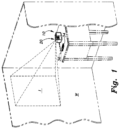
FIG. 1 is a perspective schematic view of a system and a method, and a movement or gait lab, for analyzing movement (e.g. gait) of a person as the person ambulates (e.g. walks) in accordance with an embodiment of the present invention. In FIG. 1 , a lumped mass or visual hull or visual blob segment, and a rendering of the video recording of the person ambulating as a three-dimensional stick figure with a plurality of segments representative of a skeletal model of the person, are shown in a predetermined spatial volume along with the person for purposes of illustrating the rendering of the video of the person; but it is understood that they are only displayed on the computer, and not actually in the predetermined spatial volume with the person.
FIGS. 2 a and 2 b are exploded perspective views of a sensor of the system in FIG. 1 ;
FIG. 2 c is a schematic view of the sensor in FIGS. 2 a and 2 b;
FIG. 3 depicts functionality of the system in FIG. 1 for capturing, synchronizing, and analyzing kinetic and kinematic data;
FIG. 4 is a schematic view of a person or subject performing a T-pose initial kinematic calibration, and also shows a rendering of a video recording of the person or subject as a three-dimensional stick figure with a plurality of segments representative of a skeletal model of the person or subject, of the system and method in FIG. 1 ;
FIG. 5 is a schematic view of the person or subject standing on (connected) scale for initial calibration, and also shows a rendering of a video recording of the person or subject as a three-dimensional stick figure with a plurality of segments representative of a skeletal model of the person or subject, of the system and method in FIG. 1 ;
FIG. 6 is a schematic view of the person or subject standing on (connected) scale, with one foot extended behind, for initial calibration, and also shows a rendering of a video recording of the person or subject as a three-dimensional stick figure with a plurality of segments representative of a skeletal model of the person or subject, of the system and method in FIG. 1 ;
FIGS. 7 a - 14 are graphs of exemplary reports produced for an exemplary patient by the system and method in accordance with an embodiment of the present invention that can be used to evaluate a patient or amputee, namely using variable cadence, to qualify the patient or amputee for certain levels of care and/or devices;
FIGS. 7 a and 7 b are graphs of an exemplary report produced for an exemplary patient showing data streams for the body CoM Velocity, and as well both sides of Knee Angle, Knee Angular Velocity and Weighted Foot;
FIG. 8 is a bar graph of an exemplary report produced for an exemplary patient showing variation of walking cadence in steps per minute;
FIG. 9 is a bar graph of an exemplary report produced for an exemplary patient showing variation of walking cadence in steps per minute for both limbs to compare left and right symmetry;
FIG. 10 is a bar graph of an exemplary report produced for an exemplary patient showing level ground walking cadence across three trials;
FIG. 11 is a bar graph of an exemplary report produced for an exemplary patient showing a mid-stance foot coordinate for both feet;
FIG. 12 is a graph of an exemplary report produced for an exemplary patient showing self-selected pace and step length in meters per step;
FIG. 13 is a bar graph of an exemplary report produced for an exemplary patient showing median walking step length in meters;
FIG. 14 is a bar graph of an exemplary report produced for an exemplary patient showing median walking speed in meters per second;
FIGS. 15-18 are graphs of an exemplary report produced for an exemplary patient;
FIG. 15 is a graph of vertical velocity of the center of mass in meters per second;
FIG. 16 is a graph of an L Test showing separating the data stream into different sections that can be given individual time stamps;
FIG. 17 is a graph of an L Test foot strike coordinates and hip projection for both left and right feet;
FIG. 18 is a time-table waterfall chart showing the total time to complete the entire L Test and the individual time that a subject used to complete each component;
FIG. 19 is a flow chart of a method for analyzing movement (e.g. gait) of a person as the person ambulates (e.g. walks) in accordance with an embodiment of the present invention;
FIGS. 20-22 are schematic views depicting various positions of a person's foot during ambulation or walking for the purpose of definition.
Reference will now be made to the exemplary embodiments illustrated, and specific language will be used herein to describe the same. It will nevertheless be understood that no limitation of the scope of the invention is thereby intended.
Detailed description of example embodiment(s)
Definitions
Standard anatomical terminology is used herein, specifically with reference to FIGS. 20-22 . The three orthogonal anatomical planes are the sagittal, the frontal, and the transverse planes. A sagittal plane is the vertical plane which divides the body into right and left portions. A frontal plane is the other vertical plane, and is perpendicular to the sagittal plane, dividing the body into front (anterior) and rear (posterior) sections. The frontal plane is also referred to as the coronal plane. The transverse plane is perpendicular to both the sagittal and frontal planes, and divides the body into multiple horizontal slices or cross-sections, named superior (upper) and inferior (lower) sections. Lateral refers to a direction moving away from the body centerline, and medial refers to moving closer to the body centerline. In reference to joint and limb segments, proximal means closer to the Center of Mass (CoM) of the body, and distal means farther from the center of mass of the body. Anterior means toward or from the front of the body, while posterior means toward or from the rear of the body.
Ambulation and gait cycle terminology includes a stride and a step, as shown in FIGS. 21 and 22 . A stride is either the time, or the distance, between one gait event and the repetition of that same gait event on the same side of the body. For instance, left heel strike to left heel strike is a stride. A step is the time or distance between a gait event on one side of the body and the same event on the opposite side of the body, as in the case of left heel strike to right heel strike. A step, for any one foot, can be defined from one heel contact to the next heel contact, and thus, includes a stance phase (in contact with the ground) and a swing phase (no contact with the ground).
The term “transceiver” is used herein to refer to a transmitter for transmitting a signal, a receiver for receiving a signal, or both a transmitter and a receiver. The transceiver can both send and receive, or can include a transmitter for transmitting a signal, and a receiver for receiving a signal.
Description
The present invention comprises methods and systems for capturing 3D kinematic (visual) and kinetic (load) data about a moving person, combining those data streams with software, analyzing the movement for functional benefit, and producing a report which quantifies the physical dynamics over a variety of activities. In addition, the invention comprises methods and systems for determining, documenting, and improving the functional capability of a patient with a markerless motion capture and force sensing system. The methods and systems enable an investigator to quickly set up and record full body kinematic and kinetic data, and produce clinically relevant reports that aid in optimization and documentation of patient movement. The invention provides a comprehensive method to take full-body quantitative data, record the position and orientation of each limb in a multi-segment system and the forces that linked segment model exert on the surrounding environment. In one aspect, the markerless motion-capture system can be accompanied by force sensing modules in proximity to the foot. When kinematic (visual) and kinetic (load) data are captured together, highly accurate calculations that quantify movement and joint loading are possible. These calculations can be referred to as Inverse Dynamics. When a complete data set of patient movement is available, advanced analysis techniques can use this data with a forward simulation system to quantify the effect of each joint torque on every other limb segment. These mathematical techniques can be referred to as Intersegmental Dynamics Analysis (IDA). The IDA produces a result that details the accelerations produced by joint torques, which can be referred to as Acceleration Analysis (AA). In one aspect, the method and system can further include obtaining information about the patient's physical properties, such as height, weight, mass distribution, and body fat. The method and system can then adjust a patient-specific table that enables calculation of limb lengths, mass properties and joint centers, to enable more accurate Inverse Dynamics.
In one aspect, the present invention comprises a movement or gait lab to quantify and document the functional level of an amputee. When the patient is an amputee, the patient-specific table of properties can include information on the physical properties of the prosthetic device(s). Functional level can be categorized by multiple activities or standards, such as the capacity for variable cadence, capability to perform activities of daily living (ADLs), or time required to perform certain bench-mark tasks, such as the L Test or Timed Up and Go (TUG) Test.
The method and system can comprise Data Capture Software; Biomechanics Software; Joint Torque (& Power) Calculation; Forward Dynamics Simulation; Acceleration Analysis Software; and Capability Reporting Software. Prior work in gait labs that only use kinematic (visual) data, and that did not include capturing the forces a subject exerts on the environment, compute those forces from acceleration with methods that contribute error to the movement data. Prior work that only captured kinetic data, or forces associated with a limb do not completely depict a subject due to lack of knowledge of the position of limb segments, and most commonly only capture data from one side of the subject, given the example of lower extremity devices. Wrist- or ankle-worn accelerometer-based devices have difficulty distinguishing between activity, and are not able to quantify movement or loading of a specific limb segment, as would be needed for an amputee subject.
The method and system enables a new methodology and a new price point of data analysis and reporting on the capability of a person to perform movements while, at the same time, becomes a system that can hide the complexity from the user by turning large data sets into actionable information.
As illustrated in FIGS. 1-18 , a system, indicated generally at 10 , in an example implementation in accordance with the invention is shown for analyzing movement (e.g. a gait) of a person 14 , or a person's movement (or gait). In one aspect, the person can have all of his or her natural lower limbs (i.e. legs and feet). In another aspect, the person can be an amputee and can have one (or a pair of) lower limb prosthesis(es), or a prosthetic foot, ankle, knee, leg, or combinations thereof. The term “a person's ankles, feet, shoes or lower-limb prosthesis” is intended to encompass any combination of ankle, foot, shoe or prosthesis. In one aspect, the system 10 can be a mobile movement/gait lab that can be capable of being transported and can be capable of being implemented or set up in an existing space or room without modification of the space or room. The system 10 and/or the mobile gait lab can comprise a plurality of markerless video cameras 18 , a computer 26 or one or more processors, and a pair of force sensors 30 to capture and synchronize kinematic and kinetic data as the person ambulates (e.g. walks).
The system 10 and/or the mobile movement/gait lab can comprise a plurality of markerless video cameras 18 to capture and record markerless video (kinematic) data of the person as the person ambulates. The plurality of markerless video cameras 18 can be removably disposed about a predetermined spatial volume 22 , such as a room or predetermined space. The cameras can be disposed about a perimeter of the volume, and can define the volume or perimeter. The video cameras can be positioned and located to obtain different perspectives or angles of the volume or space. In one aspect, the video cameras can be disposed on stands. In another aspect, the video cameras can be mounted to existing walls. The kinematic data capture system or hardware, or the plurality of video cameras, can be single lens USB cameras, without sensors for sensing video or other markers on the person, or depth sensors (infrared or laser) as used in other types of the system. The person and the person's limbs can be distinguished using computer software, as discussed in greater detail below. Thus, the system and the gait lab can be set up and used with greater ease and speed.
In the preferred embodiment, a markerless motion capture system provides the visual, or kinematic, data to the system. The markerless video cameras do not require knowledgeable and expensive staff to undergo the time consuming process of placing identifying marker balls of LED lights on a subject.
The video cameras can be cheap, robust, high-quality and high-frame rate video cameras. For high-quality motion capture, the cameras can be 60 Hz and can provide a 640×480 capture video. For one preferred embodiment, the cameras can be single lens cameras and can be the USB connected SLEH-00448, or the SLEH-00201, both from Sony.
The cameras can be combined with software packages that are capable of capturing 2D video from two or more viewpoints, and rendering those recordings into a 3D stick figure that represents the long bones of the human body. For example, the iPiSoft system can be used that includes the iPi Recorder, iPi Studio, and iPi Biomechanics export. The general methodology is to take a background image of each viewpoint, record a multiple vantage video section with a subject starting in a known orientation, and then match the subject movement to an animated model by subtracting the background at each frame, and matching the model to the 2D image, from each viewpoint. The work flow typically follows such a progression: video of empty capture volume 22 , subject movement video 14 , lumped massed (visual hulls) 274 , and multi-segment 3D virtual model/skeleton stick figure 266 .
In one aspect, each recording session can start with a patient wearing the sensors 30 , and standing on a vertical force scale 150 connected to the computer 26 for baseline calibration 142 . The user can be asked to stand momentarily with both feet on the scale (indicated at 144 in FIG. 5 ), and then briefly (several seconds) with each foot extended slightly behind with the toes off the ground for a calibration of that foot (indicated at 146 in FIG. 6 ). The kinematic (video) system calibration may require the use of quiet standing for a number of seconds at the beginning of a recording. As well, the subject may be asked to bounce on a toe with one leg extended behind, to create a visual and force event, or spike in both the kinematic and kinetic data streams, that could be used for synchronization.
The initial skeleton model 266 used in these systems can consist of a 16-segment human made of 1 Head, 1 Thorax, 1 Abdomen, 1 Pelvis, 2 Thigh, 2 Shank (Leg), 2 Feet, 2 Upper Arms, 2 Lower Arms, and 2 Hands. Multiple other initial models could be used in other embodiments, with more segments 270 added for more detail, at the potential cost of more time to calculate and convert the multiple 2D movement video streams to a 3D model movement.
The methods may further include, via the one or more computers, receiving physical information (indicated at 344 in FIG. 3 ) about the subject that describes a distance from one joint center to another joint center, or to a reference point. In addition, the methods could also include using joint center data, or long bone length, as an optimizing parameter to improve the accuracy of the captured kinematic data.
In addition, the system 10 and/or the mobile movement/gait lab can comprise a computer 26 with one or more processors. The computer 26 can comprise a laptop computer, a tablet computer, a desktop computer, a modified laptop computer with additional ports and/or wireless capabilities, a modified tablet computer with additional ports and/or wireless capabilities, multiple computers, etc. The computer can have one or more wireless transceivers (e.g. Bluetooth and/or wireless local area networks (LAN) transceivers), and/or one or more data ports (e.g. USB ports). The computer can have an internal and/or an external data storage device (e.g. disk drives or flash memory). The computer can have a visual display, such as a monitor, and data input, such as a keyboard or touch screen. The computer can have one or more (fixed or base) processors 28 , as discussed in greater detail below. In one aspect, the plurality of video cameras can be wired-ly coupled to the computer, such as through USB ports (or a USB bus with a plurality of ports). In another aspect, the plurality of video cameras can be wirelessly coupled to the computer.
Furthermore, the system 10 and/or the mobile movement/gait lab can comprise a pair of force sensors 30 removably affixed to a person's ankles, feet, shoes or lower limb prostheses (all indicated at 34 ) to measure force and shear (kinetic) data as the person ambulates. As stated above, the term “a person's ankles, feet, shoes or lower-limb prosthesis” is intended to encompass any combination of ankle, foot, shoe or prosthesis. The sensors can be foot-borne sensors. The sensors can be affixed to each of the person's feet/foot, ankle(s), shoe(s), prosthetic(s), or combinations thereof depending upon the person. For example, a pair of sensors can be affixed to the person's respective ankles, shoes or feet. As another example, a pair of sensors can be affixed to the person's respective prosthetic and ankle, shoe or foot. Thus, each lower limb (foot, shoe, ankle or prosthetic) of the person has a sensor affixed thereto. The sensors 30 measure force and shear (kinetic) data as the person walks. In one aspect, the sensor can be a four-axis ground reaction sensor configured to sense: 1) pressure force or vertical force, 2) anterior/posterior shear force, 3) medio/lateral shear force, and 4) torque or moment exerted between the person's ankles, feet, shoes or lower limb prostheses and a support surface 38 . The support surface can be the floor of the space. In another aspect, the sensor can be a three-axis ground reaction sensor configured to sense: 1) pressure force or vertical force, 2) anterior/posterior shear force, and 3) medio/lateral shear force.
Each sensor 30 can include a housing 42 and an attachment 46 coupled to the housing to attached the housing to the person's ankles, feet, shoes or lower limb prostheses. In addition, the housing or sensor can have a battery port 46 with an opening 50 through the housing and into the battery port. A rechargeable battery 54 can be insertable through the opening 50 and into the battery port 46 . Thus, the battery 54 can be removed from the sensor or housing and disposed on a charger. The sensor 30 can include electronics housed in the housing 42 . The sensor 30 and/or the electronics can comprise a sensor 58 , the battery power source 54 , a wireless transceiver 62 , a digital memory device 66 , and one or more (mobile) processors, which can all be disposed in the housing. In one aspect, the (mobile) processor 70 can be electrically and operatively coupled to the sensor 58 , the power source 54 , the wireless transceiver 62 , and the digital memory device 66 . In another aspect, the (mobile) processor 74 can include the wireless transceiver 62 and/or the digital memory device 66 and/or the sensor 58 , and can be electrically and operatively coupled to the battery power source 54 . The term “sensor” is used broadly herein to refer to both the sensor unit 30 including the housing, etc., and the sensor 58 itself as an electrical component. The one or more mobile processors 70 or 74 can be disposed in the housing 42 , and coupled to one of the pair of force sensors 58 . The one or more mobile processors can be configured to receive force signals, convert analog signals to digital signals, filter the signals, amplify the signals, condition the signals, compensate the signals and/or calibrate the signals. The wireless transceiver 62 is disposed in the housing, and coupled to the one or more mobile processors 70 or 74 . The one or more mobile processors can be configured to produce a time-stamped, left- or right-side identified, seven-axis vector quantity. In addition, the one or more mobile processors and the wireless transceiver can be configured to transmit the vector quantity at 120 Hz or greater in one aspect, or 60 Hz or greater in another aspect.
One previously mentioned method to synchronize the visual and force data from different wireless or wired sensors is an event in the data file itself that creates a spike in both data streams, such as bouncing on the toe with the leg extended fully behind. A second, and more preferred method, is to synchronize the wireless transmitters without the need to create an action on the part of the subject. One method to do this is the TPSN protocol, or a Timing-Sync Protocol for Sensor Networks, consisting of a level discovery phase and a synchronization phase, given that two communications between the levels and nodes are present. With one root node assigned in the network, a time signal can be sent from Node A to Node B in a level discovery phase, but subsequently all nodes can keep track of time, with Node A sending a time-stamped packet to Node B, B to C, C to D, and so on to N nodes to complete the next work. The time-stamped packet of each node's time can then be sent backwards up the chain to double the difference between each one, or create a time-stamped loop which details the lag or clock difference between each node. In this manner, the four main delay times (send time, access time, propagation time, and receive time) are accounted for during the synchronization process.
For full-body, multi-limb segment gait analysis, a 3D vector of the Ground Reaction Force (GRF) can be used for accurate Inverse Dynamics. The force and moment measurement system, in one embodiment, comprises an insole sensor with wireless capability, and at least one body-worn computer able to wirelessly receive information from the sensor. In another embodiment, the sensor can be placed on the outside of a shoe for ease of use, and to enable cleaner signal generation to describe the foot-floor interaction. The force sensor, in a preferred embodiment, can sense plantar pressure force, anterior/posterior shear force, and medio/lateral shear force. As well, the preferred sensor may sense if a torque, or moment, is exerted between the foot and floor in the plane of the ground. As well, the preferred sensor may have sensing at multiple separate locations along its length to enable sensing the complete foot-floor interaction when only a part of the foot is on the floor, such as during normal ambulation at Initial Contact (IC) when only the heel is on the ground, or at Heel Off (HO) when only the toes are on the ground.
The sensor can easily be mounted on left or right human feet independently, and can record and transmit in real time a 3-axis force of ground contact, and a single axis moment of ground contact, to a nearby Windows desktop computer. The Center of Pressure (CoP) of the 3-axis Ground Reaction Force (GRF) can be located within the area of the sensing element to enable high-quality inverse dynamics, either by sensing element, or by row and column number. Vertical force, Anterior-Posterior shear force, and Lateral shear force are all needed when any partial section of the foot is contacting the ground. The sensor can be an integrated unit that senses vertical pressure, shear, and moment, or a dual layer approach that utilizes separate sensing elements or types. Minimizing the instep cross talk of ground force-induced shear to substrate bending shear will be desired.
An insole pressure sensor, such as those from TekScan or others, can be used, but such sensors are capable of creating a force vector of one dimension, reporting only pressure, or a force normal (perpendicular) to the sensing mat. A plurality of pressure sensors can be placed on the forward section of the insole, and a separate plurality of sensors can be placed on the heel portion of the sensing device, such that a single Center of Pressure can be created for the Ground Reaction Force (GRF) no matter what partial section of the foot is loaded when in contact with the ground. Sensors in the heel can sense load at Initial Contact (IC), and sensors under the toes can sense ground loading during Heel Off (HO). The sensor can measure loading from the occurrence of Heel Strike (HS), through the entirety of stance phase, and until the instant of Toe Off (TO).
The pressure sensors may include materials that deflect in some manner, and such deflection can affect the materials' electrical resistance, and thus, cause a change in voltage.
A second layer of sensing, either integrated with the first or separate, that is capable of quantifying the anterior/posterior and medio/lateral shear forces associated with the foot can be used to create a fully accurate 3D ground reaction force vector. A single shear sensor located at the mid-foot can add accuracy to the 3D nature of the ground reaction force. Further, an even more accurate sensor can have shear sensing at the heel and at the forefoot (metatarsal heads), so that shear is accurately quantifiable during loading periods when the foot is not fully on the ground, between heel strike and foot flat (FF), and again between foot flat and toe off (TO). At heel strike, a shear sensor located at the mid-foot would not be loaded, and therefore would not sense shear forces. As well, a mid-foot location for a shear sensor would not be loaded from terminal stance to toe off, as the heel comes off the ground.
The pressure and shear sensors can be connected to the ankle worn electronics via flexible conductors. The sensor electronics may include, at least, an integrated circuit as a main processor, at least one analog-to-digital converter to receive force signals, a removable, rechargeable battery, and a wireless component to enable communication with the computer.
The sensor can include an A to D converter, microprocessor, and storage device in the form of memory. The electronics can provide for filtering of the signal, amplification, and conversion to digital format. The sensor can include various electronic components for signal conditioning, temperature compensation, analog-to-digital conversion, digital-to-analog conversion and a serial communication bus. Additionally, sensor calibration data can be stored in an onboard memory. The memory can be any volatile or non-volatile memory, such as, but not limited to, PROM, EEPROM, Flash, DRAM, eDRAM, and PROM. The memory can hold sensor calibration data.
The kinetic data can be transmitted wirelessly at a minimum of 60 Hz in one aspect, and at a minimum of 120 Hz in another aspect. For an exemplary embodiment involving sensing the left and right feet, each wireless transmitter can send a time-stamped 7-axis vector quantity (identifiable as left or right) to the receiving computer with less than a half-second delay, resulting in a 7×1 vector (t, GRFx, GRFy, GRFx, Mz, CoPr, CoPc) for each foot. The time stamp of the ankle transmitting modules can be synchronized to the kinematic data on the receiving computer at least at 10× the rate of the data transfer. Thus, if the recording was at 100 Hz, or every 0.01 sec, the time stamp synchronization can be done at 1000 Hz, for an accuracy of 1 millisecond. The wireless transmitting system can be any one of a number of well-known short range radio frequency protocols, supported by commercially available hardware developed for the purpose, such as Zigby, Near Field Communication (NFC), Local Wireless Networks, or Bluetooth.
The sensors and electronics can last at least one year, five days per week usage case of three hours a day of walking. In addition, the sensor can only need to be calibrated once every hour without more than a 2% drift in zero values, or maximum range. The use of removable batteries is useful for patient freedom, and uninterrupted workflow. It is intended that the instrumented patient can be quantified for at least an hour without the need to recharge batteries. Removable batteries are a product benefit on the regulatory side, as the mobile user can never be attached to a “mains-connected” charger. The removable batteries can be 3.7 V Li batteries in the 750 mAhr range.
As indicated above, the system 10 and/or computer 26 can have one or more (fixed or base) processors 28 configured to temporally synchronize the kinetic data from the sensors 30 (or 58 ) and the kinematic data from the video cameras 18 together. Thus, the kinematic and kinetic data can be viewed and analyzed together. In addition, the kinematic and kinetic data can be saved together as a data file. Furthermore, the kinematic and kinetic data can be presented together in one or more reports to quantify and/or qualify a person's gait.
A method 100 ( FIG. 19 ) for analyzing a gait of a person, and for utilizing the system 10 described above, includes measuring 114 3D kinetic data as the person walks with a pair of force sensors 30 or 58 affixed to a person's ankles, feet, shoes or lower limb prostheses 34 . Each of the pair of force sensors is affixed to a different one of the person's ankles, feet, shoes or lower limb prostheses. In one aspect, the method can include arranging 128 the pair of foot sensors 30 or 58 on the person's ankles, feet, shoes or lower limb prostheses 34 . The pair of foot sensors 30 or 58 can be calibrated 142 by zeroing the pair of foot sensors and having the person stand on a scale 150 one foot at a time in sequence. The scale 150 can be part of the system 10 or gait lab, and can be coupled (wirely or wirelessly) to the computer 26 . The initial calibration of the kinetic system can involve standing on a linked scale 150 (as shown in FIGS. 5 and 6 ), weighing the person or patient, asking for the left foot to be fully extended behind the person or subject, and capturing what the sensors in proximity to the foot and the vertical scale, record at the same time for calibration by the computer.
In addition, the method 100 also includes obtaining 164 3D kinematic data as the person walks with at least one markerless video camera 18 that video records the person walking without markers. In one aspect, the method can include arranging 178 a plurality of video cameras 18 at a predetermined spatial volume 22 . The plurality of video cameras 18 can be calibrated 192 by recording an initial predetermined pose of the person, such as a T-pose in FIG. 4 .
Furthermore, the method 100 includes temporally synchronizing 206 the kinetic data and the kinematic data together. In one aspect, synchronizing the data can include causing 220 a shock load scenario to create an impulse spike in both the kinetic data and the kinematic data. In one aspect, a method for proper synchronization of kinetic and kinematic data can include a standing calibration test where the person under test undergoes a shock-loading scenario that creates an impulse-like spike in both kinetic and kinematic data. In one aspect, the person can extend a leg behind him or her while quietly standing, and stubbing a toe on the ground to create a synchronization event. In addition, the initial calibration of the kinetic system can involve standing on a linked scale 150 , weighing the person or patient, asking for the left foot to be fully extended behind the person, and capturing what the sensors in proximity to the foot and the vertical scale record at the same time for calibration by the computer. Previous knee and hip studies (E. J. Alexander, Gait & Posture, 1997) reported between 11% (knee) and 18% (hip) error in calculated moment with a 1-frame shift of 120 Hz kinetic and kinematic data. Thus, there is a need for proper temporal synchronization between the two data streams. This temporal synchronization can be established either with on-board electronics on the ankle worn devices and the receiving computer, or with actions by the subject within the recording before the investigated activity, such as tapping one toe on the ground while the leg is extended behind.
In addition to temporal synchronization error, another problem is orienting the in-shoe sensed ground reaction force, nominally aligned with the Foot Segment Coordinate System (FS.sub.CS), to the Global Lab Space Coordinate System (GLS.sub.CS). In one aspect, as the foot can only produce force when on the ground, the 3D force vector reported by the in-shoe sensing could be aligned with the lab space (GLS.sub.CS) by assuming that each axis is parallel when force is produced. While that is a good assumption for the majority of the foot flat gait cycle, and the majority of time a GRF could be produced, this ignores the force generation during Initial Contact (IC) and Heel Off (HO). There is force generation during this time when the heel is in contact with the ground, before the foot segment coordinate system is in alignment with the GLS.sub.CS, which happens at foot flat. Common foot angles at heel strike can range from 10 to 15 deg, resulting in a source of error in the reported GRF if foot (FS.sub.CS), and lab space (GLS.sub.CS) alignment is assumed. This transitory response period can be minimal, and forces can be low, so error can be quantified and determined to be acceptable or not. In another aspect, the method 100 can include orienting 234 a foot segment coordinate system of either of the pair of force sensors 30 or 58 and the patient's feet, with a foot segment coordinate system of the lab space of the video cameras 18 . In one aspect, orienting the coordinate systems can include aligning a foot space vertical force component vector reported by one of the pair of sensors 30 or 58 with a lab space vertical axis created by the video camera, and potentially error correcting by assuming the force vector and vertical axis are parallel during flat foot while ignoring force generation during initial contact and heel off. In another aspect, orienting the coordinate systems can include rotating a force vector reported by one of the pair of sensors 30 or 58 using Euler Conversion matrices to the lab space coordinate system of the video camera.
In one aspect, the person 14 or patient can be an amputee with a lower limb prosthesis (such as a prosthetic foot, leg, knee, and/or ankle) on one or both legs. Thus, in addition to temporal synchronization error, and orienting coordinate systems, it may be necessary to quickly and accurately adjust segment mass properties based both on visual blob segment distribution, and choice of prosthetic componentry. One such way would be to stand quietly on a single scale 150 while wearing a pressure/vertical force monitoring system or sensors 30 or 58 . A separate method would be to manually enter the prosthetic component descriptions to utilize previously stored segment mass properties of known devices. This would enable both calibrating the kinetic sensors 30 and or 58 , and realigning the mass distribution tables for accurate representation of the recorded individual. If a standard leg segment would represent 17% of body weight on average, not only does an amputated leg have a lower percentage of total body mass, all other segments have a slightly higher percentage to bring the total to 100%. For example, a 230-pound person would fit a standard anthropomorphic table (Table 1). If that same person became a left-knee disarticulation amputee subsequently weighing 211-pounds and who kept the same limb mass distribution, and was then fitted with a 2.5-pound prosthetic knee and a half-pound prosthetic foot, then that person could have a mass distribution as found in the second table (Table 2).
TABLE-US-00001 TABLE 1 Standard Table, 230 lb Subject Left Right Head 8.10% Thorax 21.60% Abdomen 13.90% Pelvis 14.20% Thigh 10.00% 10.00% Shank (Leg) 4.65% 4.65% Foot 1.45% 1.45% Upper Arms 2.80% 2.80% Lower Arms 1.60% 1.60% Hand 0.60% 0.60% Total 100.00%
The description continues in the full USPTO document.
 Lapsed, fee not paid10 drawings