Lapsed, fee not paid11 drawings
Consumer Products · US 9,835,301 B2
Optical systems and methods for pole luminaires
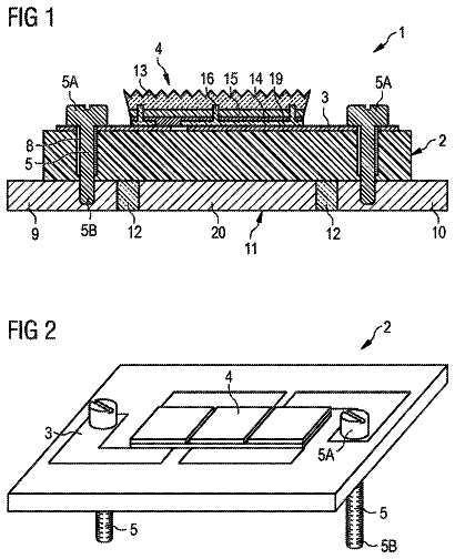
A pole luminaire mounts to a base and illuminates an area adjacent to the base.
US 9,835,337 B2 · Assignee: BAHUTONG ENTERPRISE LIMITED COMPANY · Inventors: Yeh; Yen-Jen et al.
Sheet 1 of 6 from the published document. All sheets in the USPTO PDF
A gas fireplace includes a furnace, a burner, and an air guiding device, wherein the air guiding device divides an inside of the furnace into a first chamber and a second chamber; the burner is provided in the second chamber; an air outlet of the furnace communicates with the first chamber; the air guiding device has a passageway communicating the first chamber and the second chamber, wherein a width of the passageway gradually narrows from the second chamber to the first chamber. Whereby, the hot air generated while the burner is burning gas enters the first chamber from the second chamber through the air guiding device, and then can be smoothly exhausted to outside.
As shown in FIG. 1 , a conventional gas fireplace includes a furnace 1 and a burner 2 . The furnace 1 has an air outlet 1 a , which is located at a top thereof, and an air inlet 1 b , wherein the air outlet 1 a communicates with the furnace 1 at a top thereof, and the air inlet 1 b communicates with the furnace 1 at a bottom thereof through an air channel 1 c located at a rear side of the furnace 1 . The furnace 1 is open at a front side thereof, where a toughened glass 3 is provided. The burner 2 is installed at the bottom of the furnace 1 , and the burner burns gas to produce flames, which can be seen through the toughened glass 3 from outside. While the burner 2 is burning gas, the generated hot air gradually rises to the top of the furnace 1 , and then the hot air is exhausted through the air outlet. However, the air outlet 1 b only allows part of the hot air to pass therethrough; mo
1 of 6 drawing sheets so far from the published document, cropped to the drawing. Every sheet is in the USPTO PDF.
What the patent claimed, word for word. All of it is now free to use.
The current application claims a foreign priority to application number 104122334 filed on Jul. 9, 2015 in Taiwan.
The present invention relates generally to a gas fireplace, and more particularly to a gas fireplace which has an air guiding device in a furnace thereof.
As shown in FIG. 1 , a conventional gas fireplace includes a furnace 1 and a burner 2 . The furnace 1 has an air outlet 1 a , which is located at a top thereof, and an air inlet 1 b , wherein the air outlet 1 a communicates with the furnace 1 at a top thereof, and the air inlet 1 b communicates with the furnace 1 at a bottom thereof through an air channel 1 c located at a rear side of the furnace 1 . The furnace 1 is open at a front side thereof, where a toughened glass 3 is provided. The burner 2 is installed at the bottom of the furnace 1 , and the burner burns gas to produce flames, which can be seen through the toughened glass 3 from outside.
While the burner 2 is burning gas, the generated hot air gradually rises to the top of the furnace 1 , and then the hot air is exhausted through the air outlet. However, the air outlet 1 b only allows part of the hot air to pass therethrough; most of the hot air would bump into an inner wall of the top of the furnace 1 , and then flow downwardly, which generates a turbulent air flow inside the furnace 1 . Such turbulent air flow may further hinder the exhaust of the hot air. As a result, the temperature of an outer surface of the toughened glass 3 may become so high that it may cause scalds.
In view of the above, the primary objective of the present invention is to provide a gas fireplace, which can effectively exhaust hot air generated by burning gas out from the inside of the furnace.
The present invention provides a gas fireplace, which includes a furnace, a burner, and an air guiding device. The furnace has an air outlet communicating with an inside thereof. The burner is provided in the furnace. The air guiding device is provided in the furnace, and between the air outlet and the burner, wherein the air guiding device divides the inside of the furnace into a first chamber and a second chamber; the air outlet communicates with the first chamber; the burner is provided in the second chamber; the air guiding device has a passageway communicating the first chamber and the second chamber, wherein a width the passageway gradually narrows from the second chamber to the first chamber.
In one embodiment, the gas fireplace further includes a dividing member, which is connected to an inner wall of the furnace and in the second chamber, wherein the dividing member has an opening; the burner is located below the dividing member, and corresponds to the opening; the furnace has an air inlet, which communicates with a space below the dividing member.
With the aforementioned design, the hot air generated while the burner is burning gas can be effectively guided and exhausted through the air guiding device, which prevents heat from accumulating in the furnace.
The present invention will be best understood by referring to the following detailed description of some illustrative embodiments in conjunction with the accompanying drawings, in which
FIG. 1 is a sectional view of a conventional gas fireplace;
FIG. 2 is a perspective view of a first preferred embodiment of the present invention;
FIG. 3 is a schematic view, showing the location of the air guiding device relative to the furnace;
FIG. 4 is a perspective view of the air guiding device;
FIG. 5 is a sectional view, showing the flowing of air while burning gas; and
FIG. 6 is a sectional view, showing the flowing of air while burning gas.
As shown in FIG. 2 to FIG. 6 , a gas fireplace 200 of the preferred embodiment of the present invention includes a furnace 10 , a burner 20 , and an air guiding device 30 .
The furnace 10 has a front side 101 , a rear side 102 , a left side 103 , and a right side 104 . An inner width of the furnace 10 gradually narrows from the rear side 102 to the front side 101 . The front side 101 of the furnace 10 is open, which is sealed and covered by a toughened glass 12 . The flames in the furnace 10 can be seen through the toughened glass 12 from outside.
The furnace 10 has an air outlet 105 and an air inlet 106 provided on a top thereof, wherein the air outlet 105 communicates with the inside of the furnace 10 . The air inlet 106 communicates with the furnace 10 at a bottom thereof through an air channel 107 located at the rear side 102 of the furnace 10 . The air outlet 105 and the air inlet 106 communicate with a pipe A, which is composed by an inner tube A 1 and an outer tube A 2 , wherein the inner tube A 1 communicates with the air outlet 105 , and the outer tube A 2 communicates with the air inlet 106 .
The furnace 10 further has a dividing member 14 provided therein, wherein the dividing member 14 includes a dividing plate 141 and two vertical plates 142 . The dividing plate 141 is connected to an inner wall of the furnace 10 . The dividing plate 141 has an opening 143 , wherein the vertical plates 142 are provided at where the opening 143 is. The air channel 107 communicates with a space below the dividing plate 141 .
The burner 20 is provided at the bottom of the furnace 10 below the dividing plate 141 , and corresponds to the opening 143 , wherein the burner 20 is used to burn gas. The burner 20 is a long component, which extends from the left side 103 of the furnace 10 to the right side 104 of the furnace 10 . The flames produced by the burner 20 surpass the dividing plate 141 through a space between the vertical plates 142 .
The air guiding device 30 is connected to the inner wall of the furnace 10 , and is located between the air outlet 105 and the burner 20 . The air guiding device 30 divides the furnace 10 into a first chamber S 1 and a second chamber S 2 , wherein the first chamber S 1 communicates with the air outlet 105 , and the dividing member 14 and the burner 20 are located in the second chamber S 2 . The air guiding device 30 includes a first guide plate 32 , a second guide plate 34 , a plurality of spacers 36 , and a baffle 38 . The first guide plate 32 tilts from a center of the furnace 10 toward the front side 101 ; the second guide plate 34 tilts from the center of the furnace 10 as well, but toward the rear side 102 .
The first guide plate 32 has a first top edge 321 and a first guide surface 322 , while the second guide plate 34 has a second top edge 341 and a second guide surface 342 . The first and the second top edges 321 , 341 are separated by a distance, and are parallel to each other. The first and the second top edges 321 , 341 extends in a direction parallel to the burner 20 , wherein the first top edge 321 is higher than the second top edge 341 . The guide surfaces 322 , 342 face the second chamber S 2 , and a passageway 40 is formed therebetween, which communicates the first chamber S 1 and the second chamber S 2 . A width of the passageway 40 between the front side 101 and the rear side 102 gradually decreases from bottom to top, wherein a gap 42 is formed between the first and the second top edges 321 , 341 to communicate the passageway 40 and the first chamber S 1 . The gap 42 is directly above the burner 20 , and has a long-axis direction parallel to an extending direction of the burner 20 , wherein a width of the gap 42 in the long-axis direction thereof is greater than a length of the burner 20 in the extending direction thereof.
The spacers 36 are separately arranged at the gap 42 , wherein each of spacers 36 is respectively connected to the first guide plate 32 and the second guide plate 34 , and is perpendicular to the guide surfaces 322 , 342 . The baffle 38 is fixed at the second top edge 341 of the second guide plate 34 , and is located between two of the spacers 36 which are closest to the air outlet 105 , wherein the baffle 38 corresponds to the air outlet 105 . The distances between each of these two spacers 36 , which are closet to the air outlet 105 , and the baffle 38 are identical, i.e., said two spacers 36 are symmetrically arranged at opposite sides of the baffle 38 .
As shown in FIG. 5 and FIG. 6 , while the burner 20 is burning gas, the generated hot air current rises from the second chamber S 2 , and flows into the first chamber S 1 along the guide surfaces 322 , 342 and through the gap 42 ; after that, the hot air current is exhausted through the air outlet 105 . Since the widths of the guide surfaces 322 , 342 gradually narrow from bottom to top, the flowing speed of the hot air current could be reduced as a result, and therefore the hot air could enter the first chamber S 1 more smoothly, which reduces the chance of generating a turbulent air flow inside the second chamber S 2 , and also prevents the hot air from staying in the second chamber S 2 . In this way, the temperature inside the second chamber S 2 would not become too high. Furthermore, after the hot air enters the first chamber S 1 , it could be exhausted out through the air outlet 105 more easily due to the slow speed of the hot air current inside the first chamber S 1 .
The combustion air which enters into the furnace 10 through the air inlet 106 is provided below the dividing plate 141 , and therefore it would not affect the air flow above the dividing plate 141 . In addition, the baffle 38 of the air guiding device 30 is located corresponding to the air outlet 105 to prevent the rising hot air from being too concentrated after passing through the passageway 40 . In other words, with the baffle 38 , the hot air current passes through the spaces between the spacers 36 in a distributed way, and this lowers the chance of generating the turbulent air flow. The spacers 36 are symmetrically arranged with the baffle 38 at the center, which makes the air flow enter the first chamber S 1 evenly through both sides of the baffle 38 .
In summary, the air guiding device 30 of the gas fireplace 200 provided in the present invention is capable of guiding the hot air, which helps to smoothly exhaust the hot air in the furnace 10 to outside. As a result, less heat would be accumulated in the second chamber S 2 , and the temperature of the toughened glass 12 could be lowered more effectively than the situation for a conventional gas fireplace.
It must be pointed out that the embodiments described above are only some preferred embodiments of the present invention. All equivalent structures which employ the concepts disclosed in this specification and the appended claims should fall within the scope of the present invention.
About 2,052 words. The USPTO PDF has it with every drawing.
Fees are due 3.5, 7.5 and 11.5 years after grant. This patent expired on December 5, 2025, so the fee marked "not paid" was the one that went unpaid.
GAS FIREPLACE
Filed Dec 2015 · published Jan 2017Gas fireplace
Filed Dec 2015 · granted Dec 2017Earlier publications, parents and continuations. None of them can still be enforced, or this patent would not be listed.
Prior art cited by the examiner or applicant. Useful when you check your own idea for novelty.
Everything on this page comes from the documents linked above.