Patent Yard Sign in
Lapsed, fee not paidSolo inventor

Emergency portable adjustable engine-fan assembly (fan clutch) lock-in device

US 9,835,077 B2 · Inventors: Burt; Gene Doyle

USPTO PDF

Overview

Sheet 1 of 2 from the published document. All sheets in the USPTO PDF

Abstract From the patent

An Emergency Portable Adjustable Engine-fan Assembly (fan clutch) Lock-in device, for emergency use, when engine-fan assembly (fan clutch) fails, and vehicle, large semi-truck trailer(s) combinations are forced to stop because engine oil and coolant immediately stop being properly cooled, and cannot move on own power until repaired; this device when installed allows vehicle to drive with own engine power to nearest safe-haven or repair facility.

Why it's free to use

  • The USPTO Official Gazette of February 3, 2026 lists it as expired on December 5, 2025 for an unpaid maintenance fee.
  • It isn't on any reinstatement notice published since.
  • Its 1 US relative has also lapsed, expired or never issued.
  • We check US rights only. Check foreign counterparts before selling abroad.
FiledOctober 5, 2015
GrantedDecember 5, 2017
Expired (fee)December 5, 2025
Application number14/756726
Classification (CPC)F01P5/14 +2 more
Length4 claims · 5 pages

Background From the patent

1: Field of the Invention The present invention relates to an emergency engine-fan assembly (fan clutch) lock-in device. More specifically, present invention relates to locking-keys that lock in engine-fan assembly (fan clutch) to engine hub, for continuous operation, when engine-fan assembly (fan clutch) fails. 2: Prior Art In the trucking industry many trucks equipped with certain engine-fan assemblies (fan clutch) would welcome the fact that they can be assured that when engine-fan assemblies (fan clutch) fails, present invention can be easily installed, thus acting as a safety, and cost-saving device. This gives responsible persons having the device aboard the vehicle/semi-truck combination(s) in storage for possible use in case of engine-fan assembly (fan clutch) failure confidence, and peace of mind in knowing, device can be installed, and safely driven to safe-haven or nearest rep

Drawings 2

All 2 drawing sheets from the published document, cropped to the drawing.

Claims 4 total, 2 independent

What the patent claimed, word for word. All of it is now free to use.

  1. 1
    Independent claimAn emergency portable adjustable engine-fan assembly lock-in device for use with an engine comprising a fan clutch within an engine-fan assembly, an engine hub having multiple raised humps, compression disc friction ring plate covers that are held to housing by fastener, the lock-in device comprising: a locking key body having a first end portion and a second end portion; said first end portion having recessed portions on both sides of a raised center positioning guide; each recessed portion extending from a top side and terminating in a first shoulder portion adjacent a proximal end of the second end portion; wherein said first end portion is configured to fit under and between loosened compression disc friction ring plate covers; and said second end portion having a slotted semi-circular fork at a distal end thereof configured to be positioned over a raised hump of an engine hub.
  2. 2
    The lock-in device of claim 1, further comprising an arrow on at least one of the recessed portions to indicate insertion direction.
  3. 3
    The lock-in device of claim 1, further comprising a second shoulder portion on a bottom side of the second end portion facing the distal end of the second end portion.
  4. 4
    Independent claimA method of mounting an emergency portable adjustable engine-fan assembly lock-in device in an engine comprising a fan clutch within an engine-fan assembly and an engine hub, the method comprising: mounting a plurality of lock-in devices between the fan clutch and the engine hub, each lock-in device comprising: a locking key body having a first end portion and a second end portion; said first end portion having recessed portions on both sides of a raised center positioning guide; each recessed portion extending from a top side and terminating in a first shoulder portion adjacent the second end portion; and said second end portion having a slotted semi-circular fork at a distal end thereof, turning the engine-fan until fasteners on adjacent compression disc friction ring plate covers correspond with a raised hump of engine hub; loosening said compression disc friction ring plate covers and inserting said first end portion under and between the covers such that the positioning guide extends between said compression disc friction ring plate covers and the slotted semi-circular fork engages corresponding one of the raised humps of an engine hub; applying an adequate amount of thread locker to threads of said fasteners, tightening said fasteners then repeat the same procedure with the remainder of the plurality of lock-in devices on the engine-fan assembly.

Claim map

Independent claims stand on their own. The others add detail to the claim they name.

Claim 12 claims build on it
Claim 4No claims build on it

Description

Background of the invention

1: Field of the Invention

The present invention relates to an emergency engine-fan assembly (fan clutch) lock-in device. More specifically, present invention relates to locking-keys that lock in engine-fan assembly (fan clutch) to engine hub, for continuous operation, when engine-fan assembly (fan clutch) fails.

2: Prior Art

In the trucking industry many trucks equipped with certain engine-fan assemblies (fan clutch) would welcome the fact that they can be assured that when engine-fan assemblies (fan clutch) fails, present invention can be easily installed, thus acting as a safety, and cost-saving device. This gives responsible persons having the device aboard the vehicle/semi-truck combination(s) in storage for possible use in case of engine-fan assembly (fan clutch) failure confidence, and peace of mind in knowing, device can be installed, and safely driven to safe-haven or nearest repair facility. No device is known that accomplishes in design, or objective, what this invention does in its design and objective.

Summary of the invention

1: The principal object of the present invention is to provide an emergency portable, adjustable engine-fan assembly (fan clutch) lock-in device with means to lock-in the engine-fan assembly (fan clutch), with locking-keys installed to engine hub for continuous operation, when engine-fan assembly (fan clutch) fails due to worn out clutch lining, worn out cage housing, etc., thus not maintaining proper/safe engine oil or coolant temperature, forcing vehicle/semi-truck trailer(s) combination(s) not to move on its own power. As saying goes “dead in the water”, or be subject to severe costly engine damage, due to overheating.

2: It is also an object of the present invention to provide an emergency portable adjustable engine-fan assembly (fan clutch) lock-in device that can be easily installed, and move vehicles such as huge semi-truck trailer(s) combination(s) with own power from very dangerous situations such as, side of busy two-lane road, blind spot in road, busy city traffic, mountain highway with severe weather conditions, etc. to safely drive to safe-haven or nearest repair facility, possibly preventing an accident, saving lives, and damages to vehicles due to collision(s).

3: Another object of present invention is to provide means to save thousands of dollars in down-time, and tow truck charges.

4: Another further object is to provide a device which is of simple, inexpensive construction.

5: A final object is to provide confidence and peace of mind, to operator of vehicle, semi-truck and trailer(s) combination(s) that they have the means to be in control, in a period of time, where operator has very little control over equipment.

The foregoing objects can be accomplished by providing an Emergency Portable Adjustable Engine-fan Assembly (fan clutch) Lock-in Device, where locking keys are sturdily installed.

In the preferred embodiment of present invention, the device is formed by fitting the devices three

locking-keys on the engine-fan assembly (fan clutch) in directed places, thus locking in the engine-fan assembly (fan clutch), for continuous operation.

Brief descriptions of the drawings

FIG. 1 -A: Front perspective of the drawings.

FIG. 1 -B: Back perspective of locking-key.

FIG. 1 -C: Left-side perspective of locking-key.

FIG. 1 -D: Left-side section perspective of locking-key.

FIG. 2 : Assembled view.

Detailed description

As shown in drawings, the preferred Emergency Portable Adjustable Engine-fan Assembly (fan clutch) Lock-in Device in accordance with present invention is a accomplished by three

locking keys ( 1 ) that are identical. Each is put into place, with the engine shut off, key removed from ignition key switch for safety, vehicle hood open, position self at back of engine-fan assembly (fan clutch), use hand to turn engine-fan ( 11 ) until two screws, bolts, fasteners, etc. ( 10 ), on compression disc friction ring plate cover ( 8 ) are over raised hump of engine hub ( 9 ), loosen screws, bolts, fasteners, etc. ( 10 ). Do not take completely out, pull compression disc friction ring plate cover ( 8 ) from housing, then take a locking-key ( 1 ) with arrows ( 3 ) directly facing self, pointing upward, slide and fit under and between loosened compression disc friction ring plate cover ( 8 ) screws, bolts, fasteners, etc. ( 10 ), the opposite end of locking-key ( 1 ) having proper alignment of slotted circular fork ( 4 ) over raised hump of engine hub ( 9 ), the apply an adequate amount of thread locker to threads of screws, bolts, fasteners, etc. ( 10 ), then tighten, repeat the same procedure with locking-keys ( 1 ) 2 and 3 on the engine-fan assembly (fan clutch).

Note: Alignment for locking keys ( 1 ) 2 and 3 is made after the first locking-key is installed.

Note: All three

locking-keys must be installed properly for proper operation. By hand turn engine fan ( 11 ) to make sure engine-fan assembly (fan clutch) is locked with engine-hub ( 9 ) after appropriate time for thread locker to cure, start engine, then shut off, check the device for proper fit; once satisfied device is properly installed and secure, re-start engine, drive, monitoring engine oil and coolant temperatures to nearest safe-haven, or repair facility. The device can be removed and stored for next use.

Note: This device is for emergency use only to reach safe-haven or nearest repair facility.

Timeline & family

Timeline From USPTO dates

2016201720182019202020212022202320242025Application filedOct 5, 2015Application publishedApril 6, 2017Patent grantedDec 5, 20173.5-year fee paidJune 5, 20217.5-year fee not paidJune 5, 2025Patent expiredDec 5, 2025

Maintenance fees

Fees are due 3.5, 7.5 and 11.5 years after grant. This patent expired on December 5, 2025, so the fee marked "not paid" was the one that went unpaid.

3.5-year feeDue June 5, 2021Paid
7.5-year feeDue June 5, 2025Not paid
11.5-year feeDue June 5, 2029Never came due

US family 2 documents, by filing date

Published applicationUS 2017/0096928 A1

Emergency portable adjustable engine-fan assembly (fan clutch) lock-in device

Filed Oct 2015 · published Apr 2017
Published application
This documentUS 9,835,077 B2

Emergency portable adjustable engine-fan assembly (fan clutch) lock-in device

Filed Oct 2015 · granted Dec 2017
Lapsed, fee not paid

Earlier publications, parents and continuations. None of them can still be enforced, or this patent would not be listed.

US patents it cites 4

Prior art cited by the examiner or applicant. Useful when you check your own idea for novelty.

Sources & verification

Verification

  • The USPTO Official Gazette of February 3, 2026 lists it as expired on December 5, 2025 for an unpaid maintenance fee.
  • It isn't on any reinstatement notice published since.
  • Its 1 US relative has also lapsed, expired or never issued.
  • Rechecked against USPTO records every day.
  • We check US rights only. Check foreign counterparts before selling abroad.

Confirm it yourself

  1. Open the file history on Patent Center.
  2. The status should read "Patent Expired Due to NonPayment of Maintenance Fees Under 37 CFR 1.362".
  3. Check the documents for any later petition to revive or reinstate.

Everything on this page comes from the documents linked above.

More in Vehicles & Drones

All Vehicles & Drones
Drawing from US 9,835,070 B2Lapsed, fee not paid3 drawings
Vehicles & Drones · US 9,835,070 B2

Breather hose for aqueous urea solution tank

A pressure-releasing breather hose 1 mounted on a urea water tank 2 is dividably constituted by a flexible joint portion 1 a with an end capable of being fitted over a hose joint 3 on the tank 2 , and a vertical portion…

Filed2012
LapsedDec 2025
OwnerHINO MOTORS, LTD.
Drawing from US 9,835,072 B2Lapsed, fee not paid5 drawings
Vehicles & Drones · US 9,835,072 B2

Recovered energy transfer apparatus of waste heat recovery system

A recovered energy transfer apparatus of a waste heat recovery system includes an input unit connected to an expander of the waste heat recovery system and rotatable by recovered energy of the expander, and one or more…

Filed2016
LapsedDec 2025
OwnerHYUNDAI MOTOR COMPANY
Drawing from US 9,835,088 B2Lapsed, fee not paid3 drawings
Vehicles & Drones · US 9,835,088 B2

Cooled wall

The disclosure pertains to a cooled wall for separating a hot gas flow path of a gas turbine from a cooling flow including at least one turbulator rib extending from the wall into the cooling flow, and having a height,…

Filed2013
LapsedDec 2025
OwnerANSALDO ENERGIA SWITZERLAND AG
Drawing from US 9,835,102 B2Lapsed, fee not paid1 drawing
Vehicles & Drones · US 9,835,102 B2

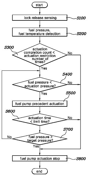
Method for controlling vehicle fuel pump

A method for controlling fuel pump of vehicle includes sensing a vehicle door lock release signal, detecting a fuel pressure in a fuel line, and actuating the fuel pump so that the fuel pressure arrives at a…

Filed2015
LapsedDec 2025
OwnerHYUNDAI MOTOR COMPANY