Cross-reference to related application
This application claims under 35 U.S.C. §119(a) the benefit of Korean Patent Application No. 10-2014-0178658 filed Dec. 11, 2014, the entire contents of which are incorporated herein by reference.
Background
(a) Technical Field
The present invention relates to a method for controlling battery State of Charge (SOC) in a hybrid electric vehicle. More particularly, the present invention relates to a method for controlling battery state of charge in a hybrid electric vehicle, which enables the efficient use of energy, the maximization of energy recovery by a motor, and the improvement of fuel efficiency and operability without the improvement of capacity and performance of electrical equipment (drive motor, Hybrid Starter and Generator (HSG), etc.) or a main battery in a hybrid electric vehicle.
(b) Background Art
Generally, internal combustion engine vehicles that use fossil fuels such as gasoline and diesel have a variety of limitations such as environmental contamination caused by the engine exhaust, global warming caused by carbon dioxide, and respiratory illnesses caused by creation of ozone. Accordingly, vehicles driven by electric power i.e., eco-friendly vehicles such as electric vehicles (EVs) driven by a motor and hybrid electric vehicles (HEVs) driven by an engine and a motor are being developed. In particular, electric vehicles and hybrid electric vehicles are equipped with a motor used as a driving source for vehicle running, an inverter and a motor controller (e.g., Motor Control Unit (MCU)), and a battery (usually referred to as ‘main battery’ or ‘high-voltage battery’) configured to supply a motor with driving power.
Additionally, electric vehicles and hybrid electric vehicles are equipped with a battery controller (e.g., Battery Management System (BMS)) configured to collect battery information. The battery controller is configured to collect battery information regarding the voltage, current, temperature, State of Charge (SOC) (%) of a battery, and is directly involved in charge and discharge control of a battery using the battery information or provides the battery information for other controllers within or extraneous a vehicle to allow the other controllers to use the battery information for the purpose of vehicle control or battery charge/discharge control.
Further, hybrid electric vehicles are equipped with an engine together with a motor (hereinafter, referred to as a ‘drive motor’) as driving sources, and a Hybrid Starter and Generator (HSG) power-transmittably connected to the engine to start the engine or generate electricity using power delivered from the engine. A main battery (e.g., high-voltage battery) used a power source of the drive motor is chargeably/dischargeably connected to the drive motor and the HSG via an inverter. The inverter is configured to convert a direct current of the battery into a three-phase alternating current (AC) for the driving of the drive motor, and apply the three-phase alternating current to the drive motor (e.g., battery discharge).
Such hybrid vehicles either drive in an electric vehicle (EV) mode which is a pure electric vehicle mode using the driving power of the drive motor, or in hybrid electric vehicle (HEV) mode which uses both driving powers of the engine and the drive motor. In addition, the regenerative mode that recovers braking or the inertial energy through the power generation of the motor during the braking of a vehicle or the coasting of a vehicle by inertia and charges power into the battery is performed. The HSG also charges the battery by operating as a generator by its own power of the engine or operating as a generator by the power delivered through the engine under the energy regenerative condition.
Meanwhile, in typical eco-friendly vehicles, the charge and discharge of a battery is adjusted based on the available output of the main battery and the required output necessary for current driving regardless of information of the vehicle speed and the road slope on the driving path. In particular, when a vehicle enters a uphill road or a low-speed section, or when a vehicle enters a downtown or a congested section and when the battery state of charge (hereinafter, referred to as ‘SOC’) (%) is low, an available motor torque is limited upon EV driving reduction and acceleration/deceleration, generating an increase of a transient control section and thus reducing the energy efficiency and operability (e.g., charge amount at idle and inefficiency operating point increases).
Further, when a vehicle enters a downhill road or a middle/high-speed section or when a vehicle enters a highway or an expressway, when the battery SOC (%) is high, an available batter space for charge is deficient upon regenerative braking and coast regeneration, making it difficult to recover extra regenerative energy and thus wasting the regenerative energy. Particularly, when there is frequent regenerative braking for maintaining a vehicle at a constant speed, or when a vehicle travels on a long-distance deceleration or downhill road such as the outlet of an expressway, regenerative energy may not be recovered and may be wasted.
In the related art, since the slope of a driving road is predicted from a signal of an accelerator (e.g., acceleration pedal) position sensor (APS), an output, a vehicle speed, or a signal of a G sensor (e.g., acceleration sensor) to determine a SOC control strategy or since the SOC control strategy is determined based on an APS signal, a brake pedal position sensor (BPS), or vehicle speed, an increase of a transient control section may occur and thus reductions of fuel efficiency and operability may be incurred due to misdetermination or determination delay according to variations (e.g., change of road load, change of acceleration or deceleration situation) of vehicle driving conditions during control section determination.
The above information disclosed in this section is merely for enhancement of understanding of the background of the invention and therefore it may contain information that does not form the prior art that is already known in this country to a person of ordinary skill in the art.
Summary
The present invention provides a method for controlling battery State of Charge (SOC) in a hybrid electric vehicle, which enables the efficient use of energy, the maximization of energy recovery by a motor, and the improvement of fuel efficiency and operability without the improvement of capacity and performance of electrical equipment (e.g., drive motor, Hybrid Starter and Generator (HSG), etc.) or a main battery in a hybrid electric vehicle.
The present invention also provides a method for controlling battery SOC in a hybrid electric vehicle, which may improve the fuel efficiency by maximizing energy recovered by a motor upon braking or coasting of a vehicle on a downhill road, a highway, or middle/high-speed driving sections The present invention further provides a method for controlling battery SOC in a hybrid electric vehicle, which may improve both operability and fuel efficiency by sufficiently securing the motor output while the vehicle is traveling on an uphill road or in a downtown or while traveling in a low-speed and congested section, thereby securing a rapid response performance with respect to a substantial required torque upon steep slope or rapid acceleration and increasing the EV travelling distance.
Additionally, the present invention provides a method for controlling battery state of charge in a hybrid electric vehicle, which may prevent reduction of operability and fuel efficiency by predicting the front slope, road type and traffic situation and thus minimizing the transient state based on the change of vehicle speed, road type, or road slope. The present invention also provides a method for controlling battery SOC in a hybrid electric vehicle, which may improve the durability of a main battery and prevent the driving disabled state of a vehicle, by predicting and restricting excess of predetermined charge and discharge limits during the charge of the main battery.
In one aspect, the present invention provides an apparatus for controlling battery State of Charge (SOC) in a hybrid electric vehicle, that may include: a driving information or road information collecting device configured to collect driving information or road information including information regarding the slope or the type of a road and information regarding the speed of a vehicle on a road; a driving information collecting device configured to collect driving information of a vehicle; and a vehicle controller configured to determine a charge mode and a discharge mode based on the driving information and determine a charging upper limit SOC and a discharging lower limit SOC based on the road slope information or the road type information of a road section on which a vehicle is traveling and the vehicle speed information in the road section, to output a charge command or a discharge command with respect to a drive motor and a hybrid starter and generator (HSG) based on the charging upper limit SOC where battery charging stops in the charge mode and the discharging lower limit SOC where battery charging starts in the discharge mode.
In another aspect, the present invention provides a method for controlling battery State of Charge (SOC) in a hybrid electric vehicle that may include: acquiring, from data received from a driving information or road information collecting device, driving information or road information including information regarding the slope or the type of a road and information regarding the speed of a vehicle on a road; acquiring driving information of a vehicle from the driving information collecting device; determining a charge mode and a discharge mode based on the driving information; determining, in a charge mode, a charging upper limit SOC based on road slope information and road type information of a road section on which a vehicle is currently traveling and vehicle speed information in the road section, or determining, in a discharge mode, a discharging lower limit SOC based on road slope information and road type information of a road section and vehicle speed information in the road section; and outputting a charge command or a discharge command with respect to a drive motor and a hybrid starter and generator (HSG) based on the charging upper limit SOC where battery charging stops in the charge mode or the discharging lower limit SOC where battery charging starts in the discharge mode.
Brief description of the drawings
The above and other features of the present invention will now be described in detail with reference to exemplary embodiments thereof illustrated the accompanying drawings which are given hereinbelow by way of illustration only, and thus are not limitative of the present invention, and wherein:
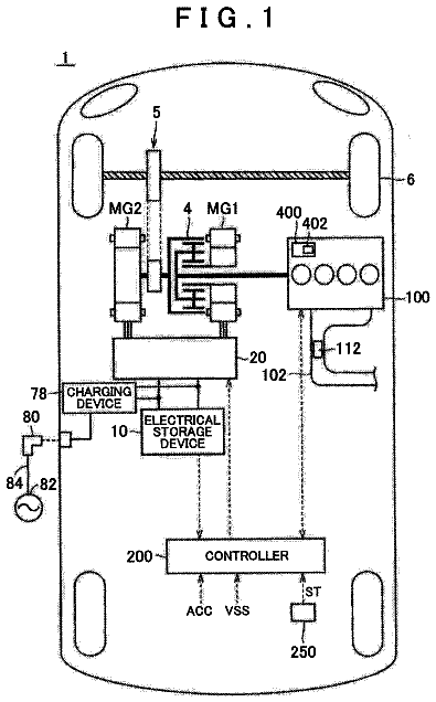
FIG. 1 is a view illustrating a system for controlling batter State of Charge (SOC) according to an exemplary embodiment of the present invention;
FIG. 2 is a flowchart illustrating a process of controlling battery SOC according to an exemplary embodiment of the present invention;
FIG. 3 is a view illustrating a method of controlling battery SOC according to an exemplary embodiment of the present invention;
FIG. 4 is a view illustrating a control state according to a road slope and a vehicle speed that is driving information in a method for controlling batter SOC according to an exemplary embodiment of the present invention;
FIG. 5 is a flowchart illustrating a process of controlling battery SOC according to another exemplary embodiment of the present invention;
FIG. 6 is a view illustrating a method of controlling battery SOC according to another exemplary embodiment of the present invention; and
FIG. 7 is a view illustrating a control state according to a road slope and a vehicle speed that is driving information in a method for controlling batter SOC according to an exemplary embodiment of the present invention.
Reference numerals set forth in the Drawings includes reference to the following elements as further discussed below: 1 : external traffic information providing system 10 : Driving Information or Road Information collecting device 11 : GPS receiver 12 : data storage unit 13 : information receiver 14 : camera sensor 15 : sensor controller 20 : battery controller 21 : battery 30 : driving information collecting device 40 : vehicle controller 50 : motor controller 51 : electrical equipment (drive motor and HSG) 60 : engine controller 61 : engine
It should be understood that the accompanying drawings are not necessarily to scale, presenting a somewhat simplified representation of various exemplary features illustrative of the basic principles of the invention. The specific design features of the present invention as disclosed herein, including, for example, specific dimensions, orientations, locations, and shapes will be determined in part by the particular intended application and use environment. In the figures, reference numbers refer to the same or equivalent parts of the present invention throughout the several figures of the drawing.
Detailed description
Although exemplary embodiment is described as using a plurality of units to perform the exemplary process, it is understood that the exemplary processes may also be performed by one or plurality of modules. Additionally, it is understood that the term controller/control unit refers to a hardware device that includes a memory and a processor. The memory is configured to store the modules and the processor is specifically configured to execute said modules to perform one or more processes which are described further below.
Furthermore, control logic of the present invention may be embodied as non-transitory computer readable media on a computer readable medium containing executable program instructions executed by a processor, controller/control unit or the like. Examples of the computer readable mediums include, but are not limited to, ROM, RAM, compact disc (CD)-ROMs, magnetic tapes, floppy disks, flash drives, smart cards and optical data storage devices. The computer readable recording medium can also be distributed in network coupled computer systems so that the computer readable media is stored and executed in a distributed fashion, e.g., by a telematics server or a Controller Area Network (CAN).
The terminology used herein is for the purpose of describing particular embodiments only and is not intended to be limiting of the invention. As used herein, the singular forms “a”, “an” and “the” are intended to include the plural forms as well, unless the context clearly indicates otherwise. It will be further understood that the terms “comprises” and/or “comprising,” when used in this specification, specify the presence of stated features, integers, steps, operations, elements, and/or components, but do not preclude the presence or addition of one or more other features, integers, steps, operations, elements, components, and/or groups thereof. As used herein, the term “and/or” includes any and all combinations of one or more of the associated listed items.
Hereinafter reference will now be made in detail to various exemplary embodiments of the present invention, examples of which are illustrated in the accompanying drawings and described below. While the invention will be described in conjunction with exemplary embodiments, it will be understood that present description is not intended to limit the invention to those exemplary embodiments. On the contrary, the invention is intended to cover not only the exemplary embodiments, but also various alternatives, modifications, equivalents and other embodiments, which may be included within the spirit and scope of the invention as defined by the appended claims.
It is understood that the term “vehicle” or “vehicular” or other similar term as used herein is inclusive of motor vehicles in general such as passenger automobiles including sports utility vehicles (SUV), buses, trucks, various commercial vehicles, watercraft including a variety of boats and ships, aircraft, and the like, and includes hybrid vehicles, electric vehicles, plug-in hybrid electric vehicles, hydrogen-powered vehicles and other alternative fuel vehicles (e.g. fuels derived from resources other than petroleum). As referred to herein, a hybrid vehicle is a vehicle that has two or more sources of power, for example both gasoline-powered and electric-powered vehicles.
Hereinafter, exemplary embodiments of the present invention will be described in detail with reference to the accompanying drawings so that those skilled in the art can easily carry out the present invention.
The present invention provides a method for controlling battery state of charge (hereinafter, referred to as ‘SOC’) in a hybrid electric vehicle, which enables the efficient use of energy, the maximization of energy recovery, and the improvement of fuel efficiency and operability without the improvement of capacity and performance of electrical equipment or a main battery in a hybrid electric vehicle. In particular, the electrical equipment relates to battery charge/discharge in a hybrid electric vehicle, and may include a hybrid starter and generator (HSG) and a drive motor that may be configured to convert braking and inertial energy of a vehicle into electric energy to charge a battery during regenerative braking or coasting.
FIG. 1 is a view illustrating a system for controlling batter SOC according to an exemplary embodiment of the present invention. Referring to FIG. 1 , the system may include a driving information or road information collecting device 10 (e.g., a sensor) configured to collect driving information or road information including information regarding a driving road, a battery controller 20 configured to collect battery information such as battery voltage (e.g., cell voltage), current, temperature and SOC (%), a driving information collecting device 30 (e.g., a sensor) configured to collect vehicle driving information, and a vehicle controller 40 configured to determine and output battery charge/discharge commands based on the driving information or road information, the battery information, and the driving information.
In particular, the driving information or road information may be collected based on the current location of a vehicle, and may include the slope information and the traffic speed (or limited speed) of the current road, the slope information of the front road and the residual distance to the front road. The slope information of the current road may be slope information of a current road section on which a vehicle is traveling, and the traffic speed information may be an average vehicle running speed determined based on the real-time traffic volume in a current road section on which a vehicle is traveling.
The driving information or road information collecting device 10 configured to collect the driving information or road information may include a global positioning system (GPS) receiver 11 configured to receive a GPS signal, a data storage unit 12 configured to store map information, and an information receiver 13 configured to receive traffic information from a traffic information providing system 1 extraneous to a vehicle. In particular, the map information may provide three-dimensional (3D) geographic information, i.e., three-dimensional road information including altitude on the two-dimensional plane, and particularly, may be 3D map data that may provide in real-time the slope information of a road while a vehicle is being driven.
In particular, the three-dimensional map data may be a map database of an advanced driver assistance system (ADAS) mounted within a vehicle. The GPS receiver 11 and the data storage unit 12 may be a navigation device installed within a vehicle. When the vehicle controller 40 detects the location of a vehicle from a GPS signal received from GPS receiver 11 , the road slope information of the road section may be obtained from the map information stored in the data storage unit 12 based on the location of a vehicle.
Additionally, when a driver sets a destination on a navigation device and then a driving path to a destination is generated, road slope information on the driving path may be acquired from 3D map data. The road on the driving path may be divided into different sections, and road slope information for each section may be acquired. In this exemplary embodiment, slope information of a road section (e.g., road section that corresponds to the detected location of a vehicle) on which a vehicle is currently traveling, and slope information of the front road section adjacent or proximate to the current road section may be acquired and used.
In this exemplary embodiment, the vehicle controller 40 may be configured to acquire and use a mean slope value of each road section as the slope information of the current road section on which a vehicle is traveling and the slope information of the front road section. Hereinafter, the mean slope value of the current road section will be referred to as ‘current mean effective road slope’, and the mean slope value of the front road section will be referred to as ‘next mean effective road slope’.
When the driving information or road information collecting device 10 collects the traffic speed information of a road on which a vehicle is traveling and the information receiver 13 receives traffic information from the external traffic information providing system (TPEG, ITS, etc.) 1 , the vehicle controller 40 may be configured to acquire, from the traffic information received from the information receiver 13 , traffic speed information of a road on which a vehicle is traveling, based on the vehicle location detected from the GPS signal.
When traffic information may not be provided by the external traffic information providing system based on area restrictions, limited speed regulated on a road on which a vehicle is currently traveling may be used. In other words, the traffic speed, i.e., the mean vehicle running speed according to the traffic of a road may be primarily used, and the limited speed regulated on the road on which a vehicle is traveling may be secondarily used. When the traffic speed information on a road is provided, the traffic speed may be used, and when the traffic speed information is not provided, the limited speed may be used.
Further, even though the running formation collecting device 10 provides the traffic information and the limited speed on the road, the actual current running speed may be different from the limited speed by a certain degree or more, or there may be multiple roads and all of the traffic information and the limited speed of which may not be provided. Accordingly, in this case, the mean vehicle speed for a particular time may be used from the vehicle speed detector that detects the current speed of a vehicle. The limited speed may be acquired from the vehicle location and the map information by the vehicle controller 40 , and information regarding the limited speed regulated on a road that corresponds to the vehicle location may be extracted from the map information.
When an imaging device (e.g., camera, video camera, or the like) sensor 14 captures a traffic sign marked with the limited speed while the vehicle is being driven, a sensor controller 15 may be configured to extract information regarding the limited speed from a captured (e.g., photographed) image using character recognition, and the limited speed information extracted by the sensor controller 15 may be delivered to the vehicle controller 40 to be analyzed.
As described above, one of the traffic speed that is a mean vehicle running speed of a driving road provided by the external traffic information providing system 1 , the limited speed regulated on the driving road, and the mean vehicle speed for a particular time from the vehicle speed detector of a vehicle may be used. Hereinafter, the traffic speed, the limited speed, and the actual mean vehicle speed will be referred to as a ‘mean effective vehicle speed’ in this disclosure.
In addition, the driving information or road information collecting device 10 may be configured to provide the vehicle controller 40 with information regarding the residual distance from the current location of a vehicle to the location of the front road section, and the residual distance information may be acquired from the location information of a vehicle and the map information. The driving information collecting device 30 configured to collect the vehicle driving information may include an accelerator pedal position sensor (APS) configured to sense an operation of an accelerator pedal (e.g., an engagement degree, an amount of pressure exerted onto the pedal, etc.), a brake pedal position sensor (BPS) configured to sense an operation of a brake pedal (e.g., an engagement degree, an amount of pressure exerted onto the pedal, etc.), and a vehicle speed detector configured to detect the current speed of a vehicle.
A motor controller 50 may be configured to receive charge/discharge commands output from the vehicle controller 40 , and may be configured to operate the electrical equipment 51 (i.e., the drive motor and the HSG that are an in-vehicle motor and an generator into driving (battery discharge)) and generative (e.g., power generation and battery charge) modes through voltage/current adjustment based on the commands. In addition, the motor controller 50 may be configured to adjust the driving output and power generation output of the drive motor and the HSG. An engine controller 60 may be configured to adjust the amount of fuel and air based on whether the engine is on or off and output commands output from the vehicle controller 40 , and thus may be configured to adjust the output of an engine 61 .
FIG. 2 is a flowchart illustrating a process of controlling battery SOC according to an exemplary embodiment of the present invention, and FIG. 3 is a view illustrating a method of controlling battery SOC according to an exemplary embodiment of the present invention. FIG. 4 is a view illustrating a control state based on a road slope and a vehicle speed that is driving information in a method for controlling batter SOC according to an exemplary embodiment of the present invention.
Referring to FIG. 2 , to describe the whole process of controlling battery SOC according to an exemplary embodiment of the present invention, the vehicle controller 40 may be configured to detect whether valid data is input from the driving information or road information collecting device 10 (S 11 ), and may be configured to acquire the road slope information and the traffic information (i.e., the driving information or road information of the current road section) from the data input from the driving information or road information collecting device 10 (S 12 ). In particular, the current mean effective road slope that is a mean slope value of the current road section on which a vehicle is traveling and the mean effective vehicle speed that is the traffic speed or the limited speed of a road on which a vehicle is traveling may be determined as the current average driving information or road information (S 13 and S 14 ).
Additionally, the vehicle controller 40 may be configured to receive an APS signal, a BPS signal, and a vehicle speed signal from the driving information collecting device 30 to acquire the driving information, and may be configured to receive battery information such as battery SOC from the battery controller 20 (S 15 ). The controller may further be configured to use the driving information and the battery information to determine whether the vehicle driving area corresponds to an active charging area (S 16 ).
In the active charging area, which is a normal charge/discharge area, charging control in which the battery is charged by the electrical equipment 51 using engine power, or discharging control in which a battery is discharged by the electrical equipment 51 to drive at an operating point of high-efficiency to maintain an engine operating point of high-efficiency while the engine is driven at an operating point of high-efficiency to maintain an engine operating point of high-efficiency may be performed while the active charge area is a regenerative braking torque and a coast regenerative torque active areas.
In response to determining that the vehicle driving area is not an active charging area but is a passive charging area (S 17 ), the passive charging control in which the recovery of electric energy is enhanced through the drive motor may be performed through the regenerative braking torque and coasting torque control. In the passive charging area, electric energy may be recovered (secured) using the discharge-oriented control and the enhanced regenerative braking and coasting torques (variable control) while the forcible charging is limited (e.g., normal charging stop). Alternatively, in response to determining that the driving area of a vehicle is a forced charging area which is a forcible charging enhancing area to secure SOC for securing EV driving and maximum output, not the active charging area (S 18 ), forced charging control may be performed based on a predetermined control logic.
While the vehicle is being driven, the vehicle controller 40 may be configured to determine from the driving information acquired using the driving information collecting device 30 whether the driving mode is a charge mode or a discharge mode (S 19 and S 20 ). When the driving mode is a charge mode, an active charging upper limit SOC at which discharge-oriented control starts may be calculated from the current driving information or road information (S 21 ). When the driving mode is a discharge mode, an active charging lower limit SOC at which discharge-oriented control starts, may be calculated from the current mean effective road slope and mean effective vehicle speed (S 22 ).
Further, the controller may be configured to determine whether a driving path to a destination set by a driver using the navigation device of a vehicle is generated (S 23 ). When the driving path is generated, the front driving information or road information may be acquired from data input from the driving information or road information collecting device 10 (S 24 ).
In particular, the next mean effective road slope that is a mean slope value of the front road section may be determined (S 25 ), and a correction factor for correcting the active charging upper limit (e.g., normal charging stop) SOC or the active charging lower limit (e.g., normal charging start) SOC may be calculated from the next mean effective road slope and the residual distance to the front road section. When the correction factor is determined, the final charging upper limit SOC and charging lower limit SOC that are corrected may be determined by multiplying the charging upper limit SOC or the charging lower limit SOC by the correction factor (S 26 ).
When no driving path is generated, since the front road information may not be determined, the charging upper limit SOC or the charging lower limit SOC of a current road calculated in operations S 21 and S 22 may be intactly applied to the final charging upper limit SOC or the final charging lower limit SOC without a correction. Thus, when the final charging upper limit SOC and charging lower limit SOC are determined, the charging start and the charging stop may be determined based on the upper limit SOC and the lower limit SOC according to the road slope and the vehicle speed while the vehicle is being driven, and the battery SOC may be adjusted by outputting charging/discharging commands such as charging allowance command, charging allowance SOC, charging coefficient, discharging allowance command, discharging allowance SOC, and discharging coefficient (S 27 ).
Referring to FIG. 3 , a process of determining the charging upper limit SOC and the charging lower limit SOC from the driving information such as the APS value, the BPS value and the vehicle speed, the current driving information or road information such as the road slope and the traffic speed (or limited speed) of the current road section, and the front driving information or road information such as the road slope of the front road section and the residual distance to the front road section is shown in more detail.
As shown in FIG. 3 , when the current and front mean effective road slopes are determined from the road slope information, and when the mean effective vehicle speed (traffic speed and limited speed) are determined from the traffic information (or map information and imaging device sensor information), a charging upper limit SOC at which charging stops from the charge mode and a charging lower limit SOC at which charging starts from the discharge mode in the active charging area may be calculated from the current mean effective road slope and the current mean effective vehicle speed using the map.
Particularly, the charging upper limit SOC may be a SOC threshold at which predetermined normal charging control stops or the (forcible) discharge-oriented control is performed to maintain the operating point of high engine efficiency or to secure the operability in the charge mode, and the charging lower limit SOC may be a SOC threshold at which normal discharging control stops and (forcible) charge-oriented control is performed in the discharge mode.
In the map, the charging upper limit SOC and the discharging lower limit SOC on an uphill road may be set higher than those on a flat road, and the charging upper limit SOC and the charging lower limit SOC on a downhill road may be set lower than those on a flat road. Additionally, as the mean effective road slope (+ %) that is a positive value on an uphill road increases, the charging lower limit SOC may be set higher. As the mean effective road slope (− %) that is a negative value on a downhill road decreases, the charging upper limit SOC may be set lower. Additionally, as the mean effective vehicle speed on a flat road decreases, the charging upper limit SOC and the charging lower limit SOC may be set higher.
As shown in FIG. 3 , the correction factor may be calculated using the map from the next mean effective road slope and the residual distance. When the correction factor is calculated, the final charging upper limit SOC may be calculated by multiplying the charging upper limit SOC determined from the current mean effective road slope and mean effective vehicle speed by the correction factor determined from the next mean effective road slope and the residual distance. Alternatively, the final charging lower limit SOC may be calculated by multiplying the charging lower limit SOC determined from the current mean effective road slope and mean effective vehicle speed by the correction factor determined from the next mean effective road slope and the residual distance.
FIG. 4 shows that the charging upper limit (e.g., normal charging stop) SOC and the charging lower limit (e.g., normal charging start) SOC change in accordance with the road slope and the vehicle speed (e.g., traffic speed or limited speed) which are driving information or road information. In this exemplary embodiment, the operability and the fuel efficiency of a hybrid electric vehicle may be improved using optimized SOC control based on the road slope and the vehicle speed.
In other words, the energy recovery rate may be improved by analyzing and determining the vehicle speed and the driving information for each road slope and thus adjusting the charging upper limit SOC into a low level in a section where the required torque is low and the regenerative braking efficiency is high. The operability and the energy efficiency may be improved by adjusting the charging lower limit SOC into a high level in a section where the required torque significantly changes and the regenerative braking efficiency is low.
In FIG. 4 , actual road slopes such as downhill road sections, flat road sections, and uphill road sections are shown. Since the mean effective road slopes applied to an actual logic are mean slope values in each road section, the mean effective road slopes may be shown as constant values. The mean effective road slope in the downhill road section may be determined as a negative value (− %), and the mean effective road slope in the flat road section may be determined as zero. The mean effective road slope in the uphill road section may be determined as a positive value (+ %).
Additionally, the charging upper limit SOC and the charging lower limit SOC which are battery SOC thresholds for charge control may be adjusted between a charging limit and a discharging limit based on the road slope and the vehicle speed. In particular, a SOC band that is defined as a section between the charging upper limit SOC and the charging lower limit SOC may be adjusted between the charging limit and the discharging limit based on the road slopes (e.g., mean effective road slope) for each road section.
First, in the downhill road section, the SOC band defined as a section between the charging upper limit SOC and the charging lower limit SOC may be set low compared to the flat road section, and in the uphill road section, the SOC band may be set high compared to the flat road section. In other words, in the downhill road section, the charging upper limit SOC (e.g., a maximum value of SOC band) and the charging lower limit SOC (e.g., a minimum value of SOC band) may be set low compared to the flat road section, maximizing energy recovery upon coasting and regenerative braking by the drive motor while the vehicle is driven on a downhill road and improving the energy recovery rate and the fuel efficiency.
Further, in the uphill road section, the charging upper limit SOC and the charging lower limit SOC may be set high compared to the flat road, securing a necessary discharge amount and, when insufficient, additionally securing discharge amount through forcible charging by the HSG while the vehicle is traveling on an uphill road. Thus, the fuel efficiency and the operability may be improved.
Moreover, the optimization of the charge/discharge area may be enabled by determining the charging upper limit SOC and the charging lower limit SOC based on the mean effective road slope and the mean effective vehicle speed in all sections of uphill, downhill, and flat roads, and the fuel efficiency and the operability may be improved. In particular, in the uphill road section, as the mean effective road slope that is a positive value decreases, the charging upper limit SOC and the charging lower limit SOC may be set lower. As the mean effective road slope increases, the charging upper limit SOC and the charging lower limit SOC may be set higher.
In the flat road section, as the mean effective vehicle speed decreases, the charging upper limit SOC and the charging lower limit SOC may be set higher. As the mean effective vehicle speed increases, the charging upper limit SOC and the charging lower limit SOC may be set lower. Thus, the optimization of charge/discharge area may be achieved by correcting the SOC band based on the change of the mean effective vehicle speed.
In the downhill road section, as the mean effective road slope that is a negative value decreases, the charging upper limit SOC and the charging lower limit SOC may be set lower. As the mean effective road slope increases, the charging upper limit SOC and the charging lower limit SOC may be set higher.
The description continues in the full USPTO document.
 Lapsed, fee not paid6 drawings