Lapsed, fee not paid8 drawings
Lapsed, fee not paid
Non-contact electric power transmission system
US 9,834,103 B2 · Assignee: TOYOTA JIDOSHA KABUSHIKI KAISHA · Inventors: Ichikawa; Shinji et al.
Overview
Sheet 1 of 5 from the published document. All sheets in the USPTO PDF
Abstract From the patent
A vehicle emits a first signal when the vehicle moves after reception of electric power from an electric power transmission device by an electric power reception device is completed and when a preparatory condition for the vehicle to move is satisfied after reception of electric power from the electric power transmission device by the electric power reception device is completed. When a charging station receives the first signal, the charging station emits a second signal notifying that a state allows charging.
Why it's free to use
- The USPTO Official Gazette of February 3, 2026 lists it as expired on December 5, 2025 for an unpaid maintenance fee.
- It isn't on any reinstatement notice published since.
- Its 1 US relative has also lapsed, expired or never issued.
- We check US rights only. Check foreign counterparts before selling abroad.
FiledJanuary 9, 2015
GrantedDecember 5, 2017
Expired (fee)December 5, 2025
Application number14/593256
Classification (CPC)B60L53/39 +7 more
Length5 claims · 11 pages
Background From the patent
Field of the Invention The present invention relates to a non-contact electric power transmission system. Description of the Background Art Japanese Patent Laying-Open No. 2013-135572 discloses a system in which electric power is transmitted in a non-contact manner, between an electric power reception device mounted on a vehicle and an electric power transmission device provided in a charging station. In this system, positioning between a coil included in an electric power transmission device and a coil included in an electric power reception device and transmission of real electric power are carried out by transmitting various types of information between a charging station and a vehicle in transmission of electric power.
Drawings 5
1 of 5 drawing sheets so far from the published document, cropped to the drawing. Every sheet is in the USPTO PDF.
Figures as described
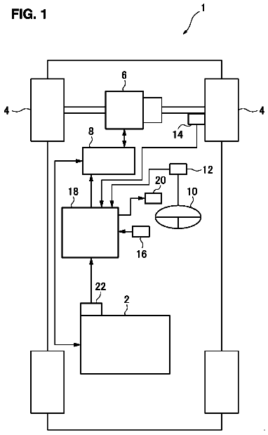
- FIG. 1 is an overall configuration diagram of a non-contact electric power transmission system representing one example of an embodiment of the present invention
- FIG. 2 is a diagram for illustrating parking of a vehicle at a parking frame within a charging station
- FIG. 3 is a flowchart for illustrating overview of processing performed by a vehicle and a charging station in non-contact electric power transmission
- FIG. 4 is a timing chart representing variation in transmission electric power and a received voltage which are varied during the course of the processing in FIG. 3
- FIG. 5 is a flowchart representing details of processing for full-scale electric power reception in step S 90 in FIG
Claims 5 total, 1 independent
What the patent claimed, word for word. All of it is now free to use.
- 1Independent claimA non-contact electric power transmission system in which electric power is transmitted between a vehicle and a charging station in a non-contact manner, comprising: the charging station, including an electric power transmission device that transmits electric power in a non-contact manner; and the vehicle, including an electric power reception device that receives electric power in a non-contact manner and a power storage device, the vehicle emitting a first signal when the vehicle moves and a preparatory condition for the vehicle to move is satisfied, after charging of the power storage device using electric power from the electric power transmission device is completed, wherein the charging station emits a second signal notifying that a state allows charging when the charging station receives the first signal.
- 2The non-contact electric power transmission system according to claim 1, wherein the vehicle emits the first signal when a speed of the vehicle exceeds a prescribed speed.
- 3The non-contact electric power transmission system according to claim 1, wherein the vehicle emits the first signal when a value obtained by summing speeds of the vehicle exceeds a prescribed value.
- 4The non-contact electric power transmission system according to claim 1, wherein the vehicle emits the first signal when a current position of the vehicle obtained from a GPS system is distant from a position of a parking frame of the charging station by a prescribed distance or more.
- 5The non-contact electric power transmission system according to claim 1, wherein the vehicle emits the first signal when a shift position of the vehicle is changed from a parking position to a drive position.
Description
This nonprovisional application is based on Japanese Patent Application No. 2014-017140 filed with the Japan Patent Office on Jan. 31, 2014, the entire contents of which are hereby incorporated by reference.
Background of the invention
Field of the Invention
The present invention relates to a non-contact electric power transmission system.
Description of the Background Art
Japanese Patent Laying-Open No. 2013-135572 discloses a system in which electric power is transmitted in a non-contact manner, between an electric power reception device mounted on a vehicle and an electric power transmission device provided in a charging station. In this system, positioning between a coil included in an electric power transmission device and a coil included in an electric power reception device and transmission of real electric power are carried out by transmitting various types of information between a charging station and a vehicle in transmission of electric power.
Summary of the invention
In the system described in Japanese Patent Laying-Open No. 2013-135572, however, when a vehicle which has completed charging moves away from an electric power transmission device, a charging station has not been able to sense movement of the vehicle away from the electric power transmission device. Consequently, another vehicle has been unable to be guided to a parking frame of the charging station. In order to sense movement of the vehicle away from the electric power transmission device, it may also be possible to provide a sensor for sensing whether or not a vehicle is present at an electric power transmission device or a parking frame, however, cost increases and installation work for attachment of the sensor requires efforts.
Therefore, an object of the present invention is to provide a non-contact electric power transmission system which can sense movement of a vehicle after charging and can guide another vehicle to a parking frame of a charging station with simplified means.
In order to solve the problem above, the present invention is directed to a non-contact electric power transmission system in which electric power is transmitted between a vehicle and a charging station in a non-contact manner, the charging station including an electric power transmission device transmitting electric power in a non-contact manner. The vehicle includes an electric power reception device receiving electric power in a non-contact manner. The vehicle emits a first signal when the vehicle moves after reception of electric power from the electric power transmission device by the electric power reception device is completed and when a preparatory condition for the vehicle to move is satisfied after reception of electric power from the electric power transmission device by the electric power reception device is completed. The charging station emits a second signal notifying that a state allows charging when the charging station receives the first signal.
According to the present invention, with simplified means, movement of a vehicle away from an electric power transmission device after charging can be sensed and another vehicle can be guided to a charging station.
The foregoing and other objects, features, aspects and advantages of the present invention will become more apparent from the following detailed description of the present invention when taken in conjunction with the accompanying drawings.
Brief description of the drawings
FIG. 1 is an overall configuration diagram of a non-contact electric power transmission system representing one example of an embodiment of the present invention.
FIG. 2 is a diagram for illustrating parking of a vehicle at a parking frame within a charging station.
FIG. 3 is a flowchart for illustrating overview of processing performed by a vehicle and a charging station in non-contact electric power transmission.
FIG. 4 is a timing chart representing variation in transmission electric power and a received voltage which are varied during the course of the processing in FIG. 3 .
FIG. 5 is a flowchart representing details of processing for full-scale electric power reception in step S 90 in FIG. 4 and processing for full-scale electric power transmission in S 590 .
Description of the preferred embodiments
An embodiment of the present invention will be described hereinafter with reference to the drawings.
(Configuration of Non-Contact Electric Power Transmission System)
FIG. 1 is an overall configuration diagram of a non-contact electric power transmission system representing one example of an embodiment of the present invention.
Referring to FIG. 1 , a non-contact electric power transmission system in the present embodiment is constituted of a vehicle 10 on which an electric power reception device 120 configured to be able to receive electric power in a non-contact manner is mounted and a charging station 90 including electric power transmission devices 20 A, 20 B, and 20 C transmitting electric power from the outside of the vehicle to an electric power reception portion 100 .
Details of a specific configuration of vehicle 10 and charging station 90 will further be described below.
Vehicle 10 includes electric power reception device 120 , a power storage device 300 , a motive power generation apparatus 400 , a communication device 510 , a vehicle ECU 500 , and a notification device 520 . Electric power reception device 120 includes electric power reception portion 100 , a filter circuit 150 , and a rectification portion 200 .
Charging station 90 includes an external power supply 900 , electric power transmission devices 20 A, 20 B, and 20 C, a communication device 810 , and a power supply ECU 800 . Electric power transmission devices 20 A, 20 B, and 20 C include power supply portions 600 A, 600 B, and 600 C, filter circuits 610 A, 610 B, and 610 C, and electric power transmission portions 700 A, 700 B, and 700 C, respectively.
For example, as shown in FIG. 2 , electric power transmission devices 20 A, 20 B, and 20 C are provided on or in the ground at parking frames A, B, and C, respectively, and electric power reception device 120 is arranged in a lower portion of a vehicle body. A location of arrangement of electric power reception device 120 is not limited as such. For example, when electric power transmission devices 20 A, 20 B, and 20 C are provided above vehicle 10 , electric power reception device 120 may be provided in an upper portion of the vehicle body.
Electric power reception portion 100 includes a secondary coil for receiving in a non-contact manner, (AC) electric power output from any of electric power transmission portions 700 A, 700 B, and 700 C of electric power transmission devices 20 A, 20 B, and 20 C. Electric power reception portion 100 outputs received electric power to rectification portion 200 . Rectification portion 200 rectifies AC power received by electric power reception portion 100 and outputs the AC power to power storage device 300 . Filter circuit 150 is provided between electric power reception portion 100 and rectification portion 200 and suppresses harmonic noise generated during electric power reception from any of electric power transmission portions 700 A, 700 B, and 700 C. Filter circuit 150 is formed, for example, from an LC filter including an inductor and a capacitor.
Power storage device 300 is a rechargeable DC power supply and it is implemented, for example, by such a secondary battery as a lithium ion battery or a nickel metal hydride battery. A voltage of power storage device 300 is, for example, around 200 V. Power storage device 300 stores not only electric power output form rectification portion 200 but also electric power generated by motive power generation apparatus 400 . Then, power storage device 300 supplies the stored electric power to motive power generation apparatus 400 . A large-capacity capacitor can also be adopted as power storage device 300 . Though not particularly illustrated, a DC-DC converter regulating an output voltage from rectification portion 200 may be provided between rectification portion 200 and power storage device 300 .
Motive power generation apparatus 400 generates driving force for running of vehicle 10 by using electric power stored in power storage device 300 . Though not particularly illustrated, motive power generation apparatus 400 includes, for example, an inverter receiving electric power from power storage device 300 , a motor driven by the inverter, and drive wheels driven by the motor. Motive power generation apparatus 400 may include a generator for charging power storage device 300 and an engine which can drive the generator.
Vehicle ECU 500 includes a central processing unit (CPU), a storage device, and an input/output buffer (none of which is shown), receives input of signals from various sensors and outputs control signals to each device, and controls each device in vehicle 10 . By way of example, vehicle ECU 500 controls running of vehicle 10 and charging of power storage device 300 . Such control is not limited to processing by software and processing with dedicated hardware (electronic circuitry) can also be performed.
A relay 210 is provided between rectification portion 200 and power storage device 300 . Relay 210 is turned on by vehicle ECU 500 during charging of power storage device 300 by electric power transmission devices 20 A, 20 B, and 20 C, A system main relay (SMR) 310 is provided between power storage device 300 and motive power generation apparatus 400 . SMR 310 is turned on by vehicle ECU 500 when start-up of motive power generation apparatus 400 is requested.
A relay 202 is provided between rectification portion 200 and relay 210 . A voltage VR across opposing ends of a resistor 201 connected in series with relay 202 is detected by a voltage sensor 203 , and sent to vehicle ECU 500 .
Vehicle ECU 500 communicates with communication device 810 of charging station 90 through communication device 510 during charging of power storage device 300 by electric power transmission devices 20 A, 20 B, and 20 C and exchanges with power supply ECU 800 , information on start/stop of charging or an electric power reception condition of vehicle 10 .
FIG. 2 is a diagram for illustrating positioning between electric power reception device 120 and electric power transmission device 20 A with movement of vehicle 10 . Referring to FIG. 2 , vehicle 10 or charging station 90 determines whether or not the secondary coil within electric power reception device 120 is positioned with respect to a primary coil within electric power transmission device 20 A based on a not-shown car-mounted camera or on intensity of received electric power during test electric power transmission (transmission of weak electric power) by electric power transmission portion 700 A, and a user is notified of a result through notification device 520 . The user moves vehicle 10 such that positional relation between electric power reception device 120 and electric power transmission device 20 A is good for electric power transmission and reception based on information obtained from notification device 520 . The user does not necessarily have to operate a steering wheel or an accelerator, and vehicle 10 may automatically move for positioning while the user monitors such an operation on notification device 520 .
Referring again to FIG. 1 , power supply portions 600 A, 600 B, and 600 C receive electric power from external power supply 900 such as a commercial system power supply and generate AC power having a prescribed transmission frequency.
Electric power transmission portions 700 A, 700 B, and 700 C each include a primary coil for non-contact electric power transmission to electric power reception portion 100 . Electric power transmission portions 700 A, 700 B, and 700 C each receive AC power having a transmission frequency from power supply portions 600 A, 600 B, and 600 C and transmit electric power to electric power reception portion 100 of vehicle 10 in a non-contact manner through electromagnetic field generated around electric power transmission portions 700 A, 700 B, and 700 C.
Filter circuits 610 A, 610 B, and 610 C are provided between power supply portions 600 A, 600 B, and 600 C and electric power transmission portions 700 A, 700 B, and 700 C, respectively, and suppress harmonic noise generated from power supply portions 600 A, 600 B, and 600 C. Filter circuits 610 A, 610 B, and 610 C are each formed from an LC filter including an inductor and a capacitor.
Power supply ECU 800 includes a CPU, a storage device, and an input/output buffer (none of which is shown), receives input of signals from various sensors and outputs control signals to each device, and controls each device in charging station 90 . By way of example, power supply ECU 800 controls switching of power supply portions 600 A, 600 B, and 600 C such that power supply portions 600 A, 600 B, and 600 C generate AC power having a transmission frequency. Such control is not limited to processing by software and processing with dedicated hardware (electronic circuitry) can also be performed.
Power supply ECU 800 communicates with communication device 510 of vehicle 10 through communication device 810 during electric power transmission to vehicle 10 , and exchanges with vehicle 10 , information on start/stop of charging or an electric power reception condition of vehicle 10 .
AC power having a prescribed transmission frequency is supplied from power supply portions 600 A, 600 B, and 600 C to electric power transmission portions 700 A, 700 B, and 700 C through filter circuits 610 A, 610 B, and 610 C. Each of electric power transmission portions 700 A, 700 B, and 700 C and electric power reception portion 100 of vehicle 10 includes a coil and a capacitor, and is designed to resonate at the transmission frequency. A Q value representing resonance intensity of electric power transmission portions 700 A, 700 B, and 700 C and electric power reception portion 100 is preferably 100 or higher.
When AC power is supplied from power supply portions 600 A, 600 B, and 600 C to electric power transmission portions 700 A, 700 B, and 700 C through filter circuits 610 A, 610 B, and 610 C, energy (electric power) is transferred from any of electric power transmission portions 700 A, 700 B, and 700 C to electric power reception portion 100 through electromagnetic field formed between the primary coil included in any of electric power transmission portions 700 A, 700 B, and 700 C and the secondary coil of electric power reception portion 100 . Then, energy (electric power) transferred to electric power reception portion 100 is supplied to power storage device 300 through filter circuit 150 and rectification portion 200 .
Though not particularly illustrated, in electric power transmission devices 20 A, 20 B, and 20 C, an insulating transformer may be provided between electric power transmission portions 700 A, 700 B, and 700 C and power supply portions 600 A, 600 B, and 600 C (for example, between electric power transmission portions 700 A, 700 B, and 700 C and filter circuits 610 A, 610 B, and 610 C). In vehicle 10 as well, an insulating transformer may be provided between electric power reception portion 100 and rectification portion 200 (for example, between electric power reception portion 100 and filter circuit 150 ).
(Procedure of Non-Contact Electric Power Transmission)
FIG. 3 is a flowchart for illustrating overview of processing performed by vehicle 10 and charging station 90 in non-contact electric power transmission. FIG. 4 is a timing chart representing variation in transmission electric power and a received voltage which are varied during the course of the processing in FIG. 3 .
Referring to FIGS. 1, 3, and 4 , when there is an empty parking frame, in step S 510 , power supply ECU 800 of charging station 90 broadcasts a message (emits a second signal) notifying that a situation allows charging through communication device 810 , in order to guide vehicle 10 to the parking frame of charging station 90 .
Timing for charging station 90 to broadcast (emit the second signal) is, for example, at the time when it determines that no vehicle is stopped above at least one of electric power transmission devices 20 A, 20 B, and 20 C of the plurality of electric power transmission devices 20 A, 20 B, and 20 C and when a broadcast signal (the first signal) from a vehicle which will be described later is received.
When vehicle ECU 500 receives the message notifying that the situation allows charging through communication device 510 in step S 40 , vehicle ECU 500 transmits a request for transmission of weak electric power for positioning through communication device 510 .
In charging station 90 , electric power transmission devices 20 A, 20 B, and 20 C transmit in step S 550 , weak electric power for positioning with electric power reception device 120 .
In step S 50 , vehicle 10 carries out positioning through automatic or manual movement of vehicle 10 (see a time point t1 in FIG. 4 ). During positioning, vehicle ECU 500 renders relay 202 conductive and obtains magnitude of a received voltage VR which is produced across the opposing ends of resistor 201 and detected by voltage sensor 203 . Since this voltage is lower than a voltage in full-scale electric power transmission, vehicle ECU 500 sets relay 210 to off so as not to be affected by power storage device 300 during detection.
When magnitude of received voltage VR has exceeded a threshold value TH, vehicle ECU 500 notifies the user in step S 60 of the fact that positioning has been successful through notification device 520 . Thereafter, when the user gives a notification that the parking position is OK by pressing a parking switch within vehicle 10 , the process proceeds to step S 70 (see a time point t2 in FIG. 4 ).
In step S 70 , vehicle ECU 500 transmits a request for stopping transmission of weak electric power for positioning. In step S 560 , power supply ECU 800 of charging station 90 receives the request for stopping transmission of weak electric power, and transmission of weak electric power for positioning by electric power transmission devices 20 A, 20 B, and 20 C ends (see a time point t3 in FIG. 4 ).
In contrast to a constant voltage on a primary side (an output voltage from electric power transmission devices 20 A, 20 B, and 20 C), a voltage on a secondary side (received voltage VR) varies in accordance with a distance between the primary coils of electric power transmission devices 20 A, 20 B, and 20 C and the secondary coil of electric power reception device 120 . Then, relation of a difference in position in a horizontal direction between center of gravity O1 of the core of the primary coil and center of gravity O2 of the core of the secondary coil with received voltage VR is determined in advance, and received voltage VR corresponding to an allowable value for the difference in position in the horizontal direction between center of gravity O1 of the core of the primary coil and center of gravity O2 of the core of the secondary coil is set as threshold value TH.
In step S 80 and step S 580 , vehicle ECU 500 and power supply ECU 800 perform pairing processing for determining with which of electric power transmission devices 20 A, 20 B, and 20 C positioning has been achieved.
Power supply ECU 800 differentiates a duration of on of transmission electric power for each electric power transmission device. Namely, electric power transmission device 20 A turns on transmission electric power for a time period of TA, electric power transmission device 20 B turns on transmission electric power for a time period of TB, and electric power transmission device 20 C turns on transmission electric power for a time period of TC (see a time point t4 in FIG. 4 ).
Vehicle ECU 500 notifies power supply ECU 800 of the duration of on of received electric power, through communication device 510 . In the example in FIG. 4 , electric power reception device 120 receives transmission electric power from electric power transmission device 20 A. Vehicle ECU 500 notifies power supply ECU 800 of the fact that the duration of on of received electric power is TA. Thus, power supply ECU 800 can know that positioning with respect to electric power transmission device 20 A has been carried out.
In step S 590 , charging station 90 performs processing for full-scale electric power transmission from the electric power transmission device which has completed positioning (see a time point t6 in FIG. 4 ). In the example in FIG. 4 , electric power transmission device 20 A performs processing for electric power transmission. In step S 90 , vehicle 10 performs processing for full-scale electric power reception by electric power reception device 120 and power storage device 300 is charged with received electric power.
FIG. 5 is a flowchart representing details of processing for full-scale electric power reception in step S 90 in FIG. 4 and processing for full-scale electric power transmission in S 590 .
Referring to FIG. 5 , in step ST 1 , vehicle ECU 500 transmits an electric power transmission start command through communication device 510 . In step ST 2 , power supply ECU 800 receives the electric power transmission start command through communication device 810 .
In step ST 3 , power supply ECU 800 has electric power transmission started. In step ST 4 , vehicle ECU 500 has charging started.
In step ST 5 , when power storage device 300 is fully charged or charged to a prescribed amount, the process proceeds to step ST 6 .
In step ST 6 and step ST 7 , vehicle ECU 500 transmits an electric power transmission stop command through communication device 510 and vehicle ECU 500 has charging stopped. In steps ST 8 and ST 9 , power supply ECU 800 receives the electric power transmission stop command through communication device 810 and power supply ECU 800 has electric power transmission stopped.
In step ST 10 , when movement of vehicle 10 is sensed, the process proceeds to step ST 11 . Here, for example, when a vehicle speed exceeds a prescribed speed, when a value obtained by summing vehicle speeds exceeds a prescribed value, when a current position of vehicle 10 obtained from a global positioning system (GPS) is distant from a position of parking frame A, B, or C by a prescribed distance or more (when vehicle 10 moves from electric power transmission device 20 A, 20 B, or 20 C), or when a shift position is changed from a parking position to a drive position (when a preparatory condition for vehicle 10 to move is satisfied), vehicle ECU 500 detects movement of vehicle 10 .
In step ST 11 , vehicle ECU 500 transmits a vehicle movement notice message (emits the first signal) through communication device 510 . In step ST 12 , power supply ECU 800 receives the vehicle movement notice message through communication device 810 . Thereafter, the process returns to step S 510 , and when there is an empty parking frame as a result of movement of vehicle 10 after a parking full state, power supply ECU 800 broadcasts a message (emits the second signal) notifying that a situation allows charging, in order to guide another vehicle to the parking frame of charging station 90 .
Thus, in the non-contact electric power transmission system according to the present embodiment, vehicle 10 broadcasts (emits the second signal) in at least one case of when vehicle 10 moves from electric power transmission device 20 A, 20 B, or 20 C after reception of electric power from any of electric power transmission devices 20 A, 20 B, and 20 C is completed and when a preparatory condition for movement from electric power transmission device 20 A, 20 B, or 20 C is satisfied after reception of electric power from electric power transmission device 20 A, 20 B, or 20 C is completed as described above. Thus, the second signal is a signal for notifying that vehicle 10 can be charged, and when the charging station determines that vehicles 10 are stopped over all electric power transmission devices, it does not broadcast to the surroundings. Thus, when a parking lot is full, guide of vehicle 10 to the charging station is prevented, and when there is free electric power transmission device 20 A, 20 B, or 20 C, new vehicle 10 is guided to the charging station.
As above, according to the present embodiment, the vehicle transmits a vehicle movement notice message to the charging station when the vehicle moves after end of charging, so that the charging station can sense movement of the vehicle away from the electric power transmission device and guide another vehicle to the charging station.
The pairing processing in step S 80 and step S 580 in FIG. 3 is not limited to the processing described above. For example, power supply ECU 800 differs a cycle of switching between on and off of transmission electric power for each electric power transmission device. Namely, electric power transmission device 20 A switches between on and off of transmission electric power every cycle ΔTA, electric power transmission device 20 B switches between on and off of transmission electric power every cycle ΔTB, and electric power transmission device 20 C switches between on and off of transmission electric power every cycle ΔTC. Vehicle ECU 500 notifies power supply ECU 800 of a cycle of switching between on and off of received electric power. For example, when electric power reception device 120 receives transmission electric power from electric power transmission device 20 A, vehicle ECU 500 notifies power supply ECU 800 of the fact that the cycle of switching between on and off of received electric power is set to ΔTA. Power supply ECU 800 thus knows that positioning with electric power transmission device 20 A has been completed.
Although the present invention has been described and illustrated in detail, it is clearly understood that the same is by way of illustration and example only and is not to be taken by way of limitation, the scope of the present invention being interpreted by the terms of the appended claims.
In this description
About 4,391 words. The USPTO PDF has it with every drawing.
Timeline & family
Timeline From USPTO dates
Maintenance fees
Fees are due 3.5, 7.5 and 11.5 years after grant. This patent expired on December 5, 2025, so the fee marked "not paid" was the one that went unpaid.
3.5-year feeDue June 5, 2021Paid
7.5-year feeDue June 5, 2025Not paid
11.5-year feeDue June 5, 2029Never came due
US family 2 documents, by filing date
Published applicationUS 2015/0217650 A1
NON-CONTACT ELECTRIC POWER TRANSMISSION SYSTEM
Filed Jan 2015 · published Aug 2015Published application
This documentUS 9,834,103 B2
Non-contact electric power transmission system
Filed Jan 2015 · granted Dec 2017Lapsed, fee not paid
Earlier publications, parents and continuations. None of them can still be enforced, or this patent would not be listed.
US patents it cites 40
US 7,193,394US 7,741,734US 2007/0222542US 2008/0278264US 2009/0195332US 2009/0195333US 2009/0224856US 2009/0267709US 2009/0267710US 2010/0096934US 2010/0102639US 2010/0102640US 2010/0102641US 2010/0117455US 2010/0117456US 2010/0123353US 2010/0123354US 2010/0123355US 2010/0127573US 2010/0127574US 2010/0127575US 2010/0133918US 2010/0133919US 2010/0133920US 2010/0171370US 2010/0181844US 2010/0187911US 2010/0201205US 2010/0207458US 2010/0225175US 2010/0231053US 2010/0237706US 2010/0237707US 2010/0237708US 2010/0253152US 2010/0264745US 2011/0187317US 2012/0323423US 2013/0127409US 2013/0193749
Prior art cited by the examiner or applicant. Useful when you check your own idea for novelty.
Sources & verification
Verification
- The USPTO Official Gazette of February 3, 2026 lists it as expired on December 5, 2025 for an unpaid maintenance fee.
- It isn't on any reinstatement notice published since.
- Its 1 US relative has also lapsed, expired or never issued.
- Rechecked against USPTO records every day.
- We check US rights only. Check foreign counterparts before selling abroad.
Confirm it yourself
- Open the file history on Patent Center.
- The status should read "Patent Expired Due to NonPayment of Maintenance Fees Under 37 CFR 1.362".
- Check the documents for any later petition to revive or reinstate.
Official USPTO records
USPTO Official GazetteNotice of Expiration of Patents Due to Failure to Pay Maintenance Fee, issue of February 3, 2026.Where this listing came fromMaintenance fee recordEnter the patent number to see its fee history.USPTO FeesFull published documentText and every drawing sheet as a PDF.USPTOFile historyStatus, office actions, notices, fee records and petitions.USPTO Patent CenterPatent Public Search recordSearchable full text and bibliographic data.USPTO
Everything on this page comes from the documents linked above.