Field
The present description relates generally to methods and systems for determining the composition of a wiper fluid injected into an engine for knock control.
Background/summary
A variety of knock control fluids have been developed to mitigate abnormal combustion events, including various combinations of gasoline, ethanol, methanol, other alcohols, water, and other inert fluids. Water injection, for example, reduces knock, provides charge cooling, and reduces the octane requirement. In addition, since water injection can also be used for engine dilution control, the need for a dedicated knock control fluid is reduced.
Another example of a knock control fluid is shown by Surnilla in U.S. Pat. No. 7,533,651. Therein, direct injection of a washer fluid, which includes water and alcohol (e.g., engine coolant or methanol) leverages the charge cooling properties of the both the fluid and the direct injection to reduce knock. In addition to protecting the water from freezing, the inclusion of engine coolant in the composition of the injected knock control fluid offers an added advantage of having light hydrocarbons (such as methanol), which help in the combustion process. The overall approach increases engine efficiency while reducing the octane requirement of injected fuel, thereby increasing the power output of the engine. Herein, the wiper fluid can be repurposed for knock control in addition to being used for cleaning a vehicle windshield.
However, the inventors herein have recognized an issue with the approach. There may be variations in windshield wiper fluid composition. For example, there may be a wide variation in the ethanol or methanol content of the fluid, as such. In addition, when a windshield wiper fluid tank is refilled, based on an amount and composition of wiper fluid that was left over in the tank, the composition of the available wiper fluid following the refilling may vary. While this does not affect the fluid's ability to clean a windshield wiper, it may affect the knock controlling ability of the fluid. For example, the octane value of the fluid may change. As such, various engine parameters are adjusted based on the injected knock control fluid. For example, based on the alcohol content of the injected fluid, cylinder fueling may be adjusted. In addition, engine parameters may need to be adjusted based on the type of alcohol in the fluid (e.g., whether the alcohol is ethanol or methanol). As a result, errors in the estimation of a wiper fluid composition can result in significant air-fuel errors, degrading engine performance. Further, if the composition of a wiper fluid is not accurately known, use of wiper fluid as a knock control fluid may be limited. On the other hand, the addition of a sensor dedicated to estimating the alcohol content and composition of a knock control fluid may add significant cost and complexity. While an intake oxygen sensor may be used to estimate the alcohol content of the knock control fluid during selected conditions, the inventors have recognized that the presence of diluents such as humidity, positive crankcase ventilation (PCV) hydrocarbons, and purge gases can cause errors in the output of the intake oxygen sensor, corrupting the estimation.
In one example, the issues described above may be addressed by a method for an engine comprising: injecting a water-alcohol blend into an engine intake initially at a first flow rate and then at a second, different flow rate; applying a reference voltage to an oxygen sensor and monitoring a change in pumping current of the sensor following each injecting; learning a first portion of the change in pumping current due to a water content of the blend; learning a second portion of the change in pumping current due to an alcohol content of the blend; and learning a third portion of the change in pumping current due to diluents in intake air. In this way, the composition of a knock control fluid injected into an engine can be accurately determined using an existing oxygen sensor, such as an intake or an exhaust oxygen sensor, with noise factors being mitigated.
As an example, following refilling of a wiper fluid tank, a wiper fluid composition may be estimated using an intake oxygen sensor. The wiper fluid may then be used as a knock control fluid. As such, the wiper fluid may include a mixture of water and alcohol but no gasoline. Further, an alcohol type in the fluid may be known a priori. For example, it may be known that the wiper fluid is a water-ethanol mixture, or a water-methanol mixture. However, a ratio of water to the specified alcohol in the fluid may not be accurately known. A controller may first inject the knock control fluid at a first gaseous volume percent into the intake manifold, downstream of an intake throttle and upstream of an intake oxygen sensor. The fluid may be injected while EGR is disabled to reduce interference on the results from EGR. A lower reference voltage (e.g., 450 mV) may then be applied to the intake oxygen sensor and an output of the sensor may be noted. For example, a first pumping current may be output. The controller may then inject the knock control fluid at a second, different gaseous volume percent into the intake manifold. The different volume percentages may be provided by injecting different amounts of the fluid at a given air mass flow rate, or by injecting a given amount of the fluid at different air as flow rates. The lower reference voltage (e.g., 450 mV) is then reapplied to the intake oxygen sensor and a second output of the sensor may be noted. For example, a second pumping current may be output. As such, the pumping currents may be affected by a reduction in the oxygen concentration at the oxygen sensor due to the water content of the knock control fluid as well as due to the alcohol content of the knock control fluid, and further due to the presence of diluents, such as PCV gas hydrocarbons, in the intake air. Specifically, the water in the knock control fluid may have a dilution effect on the oxygen sensor while the alcohol in the knock control fluid and the diluent hydrocarbons in the intake air may combust with oxygen at the sensor, reducing the oxygen concentration estimated at the sensor. An engine controller may normalize the first and second pumping currents based on the corresponding injection mass flow rates and then learn a common offset in the first and second pumping currents due to the presence of diluents in the intake air. After adjusting for the diluents, the controller may calculate the alcohol content of the knock control fluid based on the first and second normalized pumping currents, as well as the injection mass. For example, the engine controller may reference a 3D calibration map to estimate the alcohol content of the fluid, and update the composition of the fluid. By learning the composition of the fluid, the flexibility of usage of the wiper fluid as a knock control fluid may be enhanced.
It will be appreciated that while the above example discusses washer fluid composition estimation using an intake oxygen sensor, in alternate examples, the estimation may be performed using an exhaust gas oxygen sensor (such as a UEGO). Therein, the fluid may be injected at the first and second gaseous volume percent during deceleration fuel shut-off (DFSO) conditions and the composition may be determined based on a change in the pumping current of the UEGO.
In this way, an existing intake or exhaust oxygen sensor can be used to estimate the composition (including the hydrocarbon type and alcohol content) of a knock control fluid while compensating for corruption of results by intake air diluents. The technical effect of monitoring the output of an intake oxygen sensor after injecting fluid at different volume percentages is that a change in the pumping current of the sensor that is attributed to the water component of the knock control fluid can be better distinguished from the change attributed to the alcohol component of the knock control fluid without requiring adjustments to EGR, purge or PCV flow to reduce noise. This is due to the fact that the dilution effect on the oxygen sensor has a remarkably different contribution than the combustion effect of the alcohol. In addition, a common diluent based offset may be learned because the diluents cause a similar relative change in the pumping current at the different volume percentage rates. By better estimating the composition of an injected knock control fluid, the use of the knock control fluid may be expanded to engines of different fuel types, improving the robustness of the system. In addition, the accuracy of fuel octane estimates may be increased, which allows spark control to be improved. For example, spark retard usage for knock control may be reduced providing fuel economy benefits. By learning the noise in the pumping currents cause by the presence of intake air diluents, the knock control fluid can be estimated accurately even when purge or EGR is present. By using an existing intake oxygen sensor to determine the composition of the knock control fluid, the need for a dedicated sensor is reduced without compromising on the accuracy of the estimation.
It should be understood that the summary above is provided to introduce in simplified form a selection of concepts that are further described in the detailed description. It is not meant to identify key or essential features of the claimed subject matter, the scope of which is defined uniquely by the claims that follow the detailed description. Furthermore, the claimed subject matter is not limited to implementations that solve any disadvantages noted above or in any part of this disclosure.
Brief description of the drawings
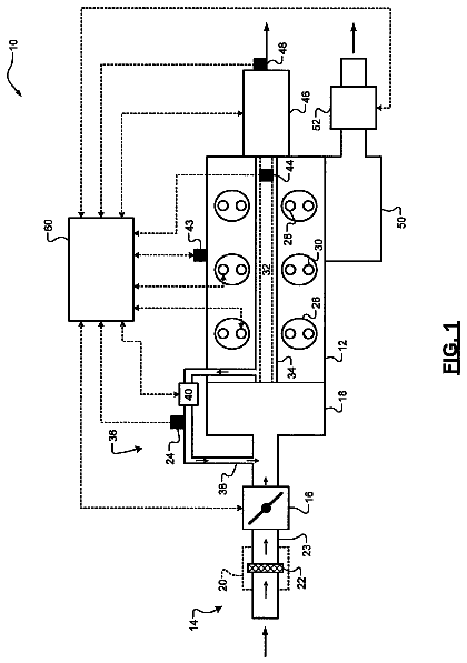
FIG. 1 shows a schematic diagram of an engine system.
FIG. 2 shows a detailed diagram of an engine combustion chamber.
FIG. 3 shows a schematic diagram of an example intake oxygen sensor.
FIG. 4 shows a flow chart illustrating a routine for using an intake oxygen sensor for knock control fluid alcohol estimation while compensating for interference from intake air diluents.
FIG. 5 shows a map demonstrating an example relationship between an alcohol content of a knock control fluid relative and each of a change in the pumping current of an oxygen sensor, and a mass of the knock control fluid injected into an engine, before compensating for the effect of diluents.
FIG. 6 shows a map demonstrating an example relationship between an air mass flow rate at which a knock control fluid is injected and an estimated alcohol concentration of the knock control fluid based on an intake oxygen sensor output, the map used for determining an offset for compensating for the effect of diluents on the output of the intake oxygen sensor.
FIG. 7 shows a flow chart illustrating a routine for using an exhaust oxygen sensor for knock control fluid alcohol estimation while compensating for interference from intake air diluents.
FIG. 8 shows a map demonstrating the relationship between the molar oxygen percentage estimated by an exhaust oxygen sensor and the molar percentage of washer fluid in an intake air stream.
Detailed description
The following description relates to systems and methods for determining the composition of a knock control fluid injected into an engine, such as the engine of FIGS. 1-2 , based on outputs from an intake or exhaust oxygen sensor, such as the sensor of FIG. 3 . As such, the oxygen sensor may be used during different engine operating conditions to estimate the alcohol content of a fuel delivered to the engine during engine combustion, or the alcohol composition of the knock control fluid delivered to the engine responsive to an indication of knock ( FIG. 3 ). An engine controller may be configured to perform a control routine, such as the example routine of FIGS. 4 and 7 , to estimate the composition of the knock control fluid, including the alcohol content and the hydrocarbon content of the fluid, based on a relative change in the pumping current of the oxygen sensor following injection of the fluid at different injection rates. The controller may reference a map, such as the example map of FIGS. 5-6 and 8 , to correlate the change in pumping current and the injection mass with the alcohol content of the injected fluid. One or more engine operating parameters such as spark timing and/or fuel injection amount may be adjusted based on the determined composition of the knock control fluid. In this manner, engine knock control fluid usage may be expanded.
FIG. 1 shows a schematic depiction of an example turbocharged engine system 100 including a multi-cylinder internal combustion engine 10 and twin turbochargers 120 and 130 . As one non-limiting example, engine system 100 can be included as part of a propulsion system for a passenger vehicle. Engine system 100 can receive intake air via intake passage 140 . Intake passage 140 can include an air filter 156 and an EGR throttle valve 131 . Engine system 100 may be a split-engine system wherein intake passage 140 is branched downstream of EGR throttle valve 131 into first and second parallel intake passages, each including a turbocharger compressor. Specifically, at least a portion of intake air is directed to compressor 122 of turbocharger 120 via a first parallel intake passage 142 and at least another portion of the intake air is directed to compressor 132 of turbocharger 130 via a second parallel intake passage 144 of the intake passage 140 .
The first portion of the total intake air that is compressed by compressor 122 may be supplied to intake manifold 160 via first parallel branched intake passage 146 . In this way, intake passages 142 and 146 form a first parallel branch of the engine's air intake system. Similarly, a second portion of the total intake air can be compressed via compressor 132 where it may be supplied to intake manifold 160 via second parallel branched intake passage 148 . Thus, intake passages 144 and 148 form a second parallel branch of the engine's air intake system. As shown in FIG. 1 , intake air from intake passages 146 and 148 can be recombined via a common intake passage 149 before reaching intake manifold 160 , where the intake air may be provided to the engine.
A first EGR throttle valve 131 may be positioned in the engine intake upstream of the first and second parallel intake passages 142 and 144 , while a second air intake throttle valve 158 may be positioned in the engine intake downstream of the first and second parallel intake passages 142 and 144 , and downstream of the first and second parallel branched intake passages 146 and 148 , for example, in common intake passage 149 .
In some examples, intake manifold 160 may include an intake manifold pressure sensor 182 for estimating a manifold pressure (MAP) and/or an intake manifold temperature sensor 183 for estimating a manifold air temperature (MCT), each communicating with controller 12 . Intake passage 149 can include a charge air cooler (CAC) 154 and/or a throttle (such as second throttle valve 158 ). The position of throttle valve 158 can be adjusted by the control system via a throttle actuator (not shown) communicatively coupled to controller 12 . An anti-surge valve 152 may be provided to selectively bypass the compressor stages of turbochargers 120 and 130 via bypass passage 150 . As one example, anti-surge valve 152 can open to enable flow through bypass passage 150 when the intake air pressure upstream of the compressors attains a threshold value.
Intake manifold 160 may further include an intake gas oxygen sensor 172 . In one example, the oxygen sensor is a UEGO sensor, such as the example UEGO sensor of FIG. 3 . As elaborated herein, the intake gas oxygen sensor may be configured to provide an estimate regarding the oxygen content of fresh air received in the intake manifold. In addition, when EGR is flowing, a change in oxygen concentration at the sensor may be used to infer an EGR amount and used for accurate EGR flow control. Further still, during selected fueling conditions, the reference voltage of the sensor may be modulated and the corresponding change in current may be used to infer the alcohol content of an injected fuel. As also elaborated herein, during selected engine fueling conditions, a knock control fluid is injected at different injection flow rates (or volume percentages), following which the reference voltage is applied to the sensor. Based on the corresponding change in current, a controller may infer and distinguish the water content of the injected fluid from the alcohol content of the injected fluid. In the depicted example, oxygen sensor 162 is positioned upstream of throttle 158 and downstream of charge air cooler 154 . However, in alternate embodiments, the oxygen sensor may be positioned upstream of the CAC.
A pressure sensor 174 may be positioned alongside the oxygen sensor for estimating an intake pressure at which an output of the oxygen sensor is received. Since the output of the oxygen sensor is influenced by the intake pressure, a reference oxygen sensor output may be learned at a reference intake pressure. In one example, the reference intake pressure is a throttle inlet pressure (TIP) where pressure sensor 174 is a TIP sensor. In alternate examples, the reference intake pressure is a manifold pressure (MAP) as sensed by MAP sensor 182 .
Engine 10 may include a plurality of cylinders 14 . In the depicted example, engine 10 includes six cylinders arrange in a V-configuration. Specifically, the six cylinders are arranged on two banks 13 and 15 , with each bank including three cylinders. In alternate examples, engine 10 can include two or more cylinders such as 3, 4, 5, 8, 10 or more cylinders. These various cylinders can be equally divided and arranged in alternate configurations, such as V, in-line, boxed, etc. Each cylinder 14 may be configured with a fuel injector 166 . In the depicted example, fuel injector 166 is a direct in-cylinder injector. However, in other examples, fuel injector 166 can be configured as a port based fuel injector.
Intake air supplied to each cylinder 14 (herein, also referred to as combustion chamber 14 ) via common intake passage 149 may be used for fuel combustion and products of combustion may then be exhausted from via bank-specific parallel exhaust passages. In the depicted example, a first bank 13 of cylinders of engine 10 can exhaust products of combustion via a first parallel exhaust passage 17 and a second bank 15 of cylinders can exhaust products of combustion via a second parallel exhaust passage 19 . Each of the first and second parallel exhaust passages 17 and 19 may further include a turbocharger turbine. Specifically, products of combustion that are exhausted via exhaust passage 17 can be directed through exhaust turbine 124 of turbocharger 120 , which in turn can provide mechanical work to compressor 122 via shaft 126 in order to provide compression to the intake air. Alternatively, some or all of the exhaust gases flowing through exhaust passage 17 can bypass turbine 124 via turbine bypass passage 123 as controlled by wastegate 128 . Similarly, products of combustion that are exhausted via exhaust passage 19 can be directed through exhaust turbine 134 of turbocharger 130 , which in turn can provide mechanical work to compressor 132 via shaft 136 in order to provide compression to intake air flowing through the second branch of the engine's intake system. Alternatively, some or all of the exhaust gas flowing through exhaust passage 19 can bypass turbine 134 via turbine bypass passage 133 as controlled by wastegate 138 .
In some examples, exhaust turbines 124 and 134 may be configured as variable geometry turbines, wherein controller 12 may adjust the position of the turbine impeller blades (or vanes) to vary the level of energy that is obtained from the exhaust gas flow and imparted to their respective compressor. Alternatively, exhaust turbines 124 and 134 may be configured as variable nozzle turbines, wherein controller 12 may adjust the position of the turbine nozzle to vary the level of energy that is obtained from the exhaust gas flow and imparted to their respective compressor. For example, the control system can be configured to independently vary the vane or nozzle position of the exhaust gas turbines 124 and 134 via respective actuators.
Exhaust gases in first parallel exhaust passage 17 may be directed to the atmosphere via branched parallel exhaust passage 170 while exhaust gases in second parallel exhaust passage 19 may be directed to the atmosphere via branched parallel exhaust passage 180 . Exhaust passages 170 and 180 may include one or more exhaust after-treatment devices, such as a catalyst, and one or more exhaust gas sensors 228 .
In one example, exhaust gas sensor 228 is an oxygen sensor such as a UEGO sensor. An example embodiment of the UEGO sensor is provided at FIG. 3 . As elaborated herein, the exhaust gas oxygen sensor may be used to estimate the oxygen content of exhaust in the intake manifold and infer an air-fuel ratio (AFR) amount for accurate AFR control. Further still, during selected engine non-fueling conditions, the reference voltage of the sensor may be modulated and the corresponding change in current may be used to infer the alcohol content of a combusted fuel. As also elaborated herein, during selected non-fueling conditions, a knock control fluid may be injected at different injection flow rates (or volume percentages), and the reference voltage of the sensor may be applied. Based on the resulting change in current, a controller may infer and distinguish the water content of the injected fluid from the alcohol content of the injected fluid.
Engine 10 may further include one or more exhaust gas recirculation (EGR) passages, or loops, for recirculating at least a portion of exhaust gas from the exhaust manifold to the intake manifold. These may include high-pressure EGR loops for proving high-pressure EGR (HP-EGR) and low-pressure EGR-loops for providing low-pressure EGR (LP-EGR). In one example, HP-EGR may be provided in the absence of boost provided by turbochargers 120 , 130 , while LP-EGR may be provided in the presence of turbocharger boost and/or when exhaust gas temperature is above a threshold. In still other examples, both HP-EGR and LP-EGR may be provided simultaneously.
In the depicted example, engine 10 may include a low-pressure EGR loop 202 for recirculating at least some exhaust gas from the first branched parallel exhaust passage 170 , downstream of the turbine 124 , to the first parallel intake passage 142 , upstream of the compressor 122 . In some embodiments, a second low-pressure EGR loop (not shown) may be likewise provided for recirculating at least some exhaust gas from the second branched parallel exhaust passage 180 , downstream of the turbine 134 , to the second parallel intake passage 144 , upstream of the compressor 132 . LP-EGR loop 202 may include LP-EGR valve 204 for controlling an EGR flow (i.e., an amount of exhaust gas recirculated) through the loops, as well as an EGR cooler 206 for lowering a temperature of exhaust gas flowing through the EGR loop before recirculation into the engine intake. Under certain conditions, the EGR cooler 206 may also be used to heat the exhaust gas flowing through LP-EGR loop 202 before the exhaust gas enters the compressor to avoid water droplets impinging on the compressors.
Engine 10 may further include a first high-pressure EGR loop 208 for recirculating at least some exhaust gas from the first parallel exhaust passage 17 , upstream of the turbine 124 , to intake manifold 160 , downstream of intake throttle 158 . Likewise, the engine may include a second high-pressure EGR loop (not shown) for recirculating at least some exhaust gas from the second parallel exhaust passage 18 , upstream of the turbine 134 , to the second branched parallel intake passage 148 , downstream of the compressor 132 . EGR flow through HP-EGR loops 208 may be controlled via HP-EGR valve 210 .
A PCV port 102 may be configured to deliver crankcase ventilation gases (blow-by gases) to the engine intake manifold along second parallel intake passage 144 . In some embodiments, flow of PCV air through PCV port 102 may be controlled by a dedicated PCV port valve. Thus, when the PCV valve is closed, crankcase ventilation to the engine intake is disabled. Likewise, a purge port 104 may be configured to deliver purge gases from a fuel system canister to the engine intake manifold along passage 144 . In some embodiments, flow of purge air through purge port 104 may be controlled by a dedicated purge port valve. Thus, when the purge valve is closed, fuel vapor purging to the engine intake is disabled
Humidity sensor 112 and pressure sensor 114 may be included in only one of the parallel intake passages (herein, depicted in the first parallel intake air passage 142 but not in the second parallel intake passage 144 ), downstream of EGR throttle valve 131 . Specifically, the humidity sensor and the pressure sensor may be included in the intake passage not receiving the PCV or purge air. Humidity sensor 112 may be configured to estimate a relative humidity of the intake air. In one embodiment, humidity sensor 112 is an oxygen sensor configured to estimate the relative humidity of the intake air based on the output of the sensor at one or more voltages. Since purge air and PCV air can confound the results of the humidity sensor, the purge port and PCV port are positioned in a distinct intake passage from the humidity sensor. Pressure sensor 114 may be configured to estimate a pressure of the intake air. In some embodiments, a temperature sensor may also be included in the same parallel intake passage, downstream of the EGR throttle valve 131 .
Intake oxygen sensor 172 may be used, during selected conditions, for estimating an intake oxygen concentration and inferring an amount of EGR dilution at the engine based on a change in the intake oxygen concentration upon opening of the EGR valve 204 . For example, upon applying a reference voltage (Vs) to the sensor, a pumping current (Ip) is output by the sensor. The change in oxygen concentration may be proportional to the change in pumping current (delta Ip) output by the sensor. Likewise, during other selected conditions, intake oxygen sensor 172 may be used for estimating the water content of intake charge (that is, ambient humidity) or the water content of an injected fuel (and inferring the alcohol content of the injected fuel). Further still, as elaborated herein, during other conditions, the intake oxygen sensor may be used for estimating the water content and alcohol content of a knock control fluid and estimating a composition of the knock control fluid accordingly. In one example, the knock control fluid is a wiper fluid and is injected into the intake manifold at two or more different injection flow rates to provide distinct volume percentages. The reference voltage (Vs) may be applied to the sensor and a change in pumping current (Ip) output by the sensor may be learned following each injection at the different injection flow rates. A first portion of the change in pumping current (delta Ip) output by the sensor that is due to the water content of the injected knock control fluid may be learned, and distinguished from a second portion of the change in pumping current that is due to the alcohol content of the injected knock control fluid. In addition, by learning the change in pumping currents at two distinct injection flow rates, a common offset in the pumping currents resulting from the presence of diluents and other hydrocarbons interfering with the reaction at the oxygen sensor's sensing element may be learned, and used to correct the pumping currents, without requiring any change in EGR, purge or PCV flow during the estimation.
The position of intake and exhaust valves of each cylinder 14 may be regulated via hydraulically actuated lifters coupled to valve pushrods, or via a direct acting mechanical bucket system in which cam lobes are used. In this example, at least the intake valves of each cylinder 14 may be controlled by cam actuation using a cam actuation system. Specifically, the intake valve cam actuation system 25 may include one or more cams and may utilize variable cam timing or lift for intake and/or exhaust valves. In alternative embodiments, the intake valves may be controlled by electric valve actuation. Similarly, the exhaust valves may be controlled by cam actuation systems or electric valve actuation.
Engine system 100 may be controlled at least partially by a control system 15 including controller 12 and by input from a vehicle operator via an input device (not shown). Control system 15 is shown receiving information from a plurality of sensors 16 (various examples of which are described herein at FIG. 1 and FIG. 2 ) and sending control signals to a plurality of actuators 81 . As one example, sensors 16 may include humidity sensor 112 , intake air pressure sensor 114 , MAP sensor 182 , MCT sensor 183 , TIP sensor 174 , UEGO 228 , and intake air oxygen sensor 172 . In some examples, common intake passage 149 may further include a throttle inlet temperature sensor for estimating a throttle air temperature (TCT). In other examples, one or more of the EGR passages may include pressure, temperature, and air-to-fuel ratio sensors, for determining EGR flow characteristics. As another example, actuators 81 may include fuel injector 166 , HP-EGR valves 210 and 220 , LP-EGR valves 204 and 214 , throttle valves 158 and 131 , and wastegates 128 , 138 . Other actuators, such as a variety of additional valves and throttles, may be coupled to various locations in engine system 100 , such as those described with reference to FIG. 2 . The controller 12 receives signals from the various sensors of FIG. 1 (and FIG. 2 ) and employs the various actuators of FIG. 1 (and FIG. 2 ) to adjust engine operation based on the received signals and instructions stored on a memory of the controller. For example, controller 12 may receive input data from the various sensors, process the input data, and trigger the actuators in response to the processed input data based on instruction or code programmed therein corresponding to one or more routines. Example control routines are described herein with regard to FIGS. 4 and 7 .
FIG. 2 depicts a detailed embodiment of a combustion chamber, such as a combustion chamber of engine 10 of FIG. 1 . Components previously introduced in FIG. 1 are numbered similarly and not reintroduced.
Engine 10 may receive control parameters from a control system including controller 12 and input from a vehicle operator 230 via an input device 232 . In this example, input device 232 includes an accelerator pedal and a pedal position sensor 234 for generating a proportional pedal position signal PP. Cylinder (herein also “combustion chamber’) 14 of engine 10 may include combustion chamber walls 236 with piston 238 positioned therein. Piston 238 may be coupled to crankshaft 240 so that reciprocating motion of the piston is translated into rotational motion of the crankshaft. Crankshaft 240 may be coupled to at least one drive wheel of the passenger vehicle via a transmission system. Further, a starter motor may be coupled to crankshaft 240 via a flywheel to enable a starting operation of engine 10 .
Engine 10 is coupled in a vehicle system 100 that includes a windshield wiper system that enables cleaning of a vehicle windshield 68 . Windshield 68 may be a front or rear windshield of a vehicle. The windshield wiper system includes at least one windshield wiper 70 operated by wiper motor 72 . In response to an operator demand, and based on input from controller 12 , wiper motor 72 may be energized causing wiper 70 to make multiple sweeping cycles known as wipes or sweeps over windshield 68 . The wipes or sweeps enable wiper blade 71 to remove moisture, debris, and foreign particles from the surface of windshield 68 . While operating wiper motor 72 and while wiper blade 71 is sweeping, based on request from a vehicle operator, controller 12 may intermittently inject or squirt a wiper fluid onto the windshield via wiper injector 74 . Wiper fluid may be stored in a reservoir 76 from where it is delivered to the windshield. As elaborated herein, reservoir 76 may be further coupled to the intake passage as well as the engine cylinder. This allows the wiper fluid to be injected to provide knock control in addition to being used for windshield wiping purposes. Specifically, the wiper fluid may be injected into the intake manifold, specifically into intake passage 246 , downstream of the intake throttle, during knock conditions, thereby enabling the windshield wiper fluid to be used as a knock control fluid. Additionally, or alternatively, windshield wiper fluid may be directly injected into an engine cylinder via direct injector, such as via the direct fuel injector or a dedicated direct fuel injector, to provide knock control. The wiper fluid stored in reservoir 76 may include a combination of water and alcohol, such as methanol or isopropanol. However, the wiper fluid does not contain any gasoline.
As such, there may be significant variation in the water: alcohol content of the wiper fluid. To enable the wiper fluid to be reliably used as a knock control fluid, a composition of the wiper fluid may need to be known. As elaborated with reference to FIG. 1 , during selected conditions, such as immediately after the wiper fluid reservoir has been refilled, an intake oxygen sensor, such as sensor 172 , may be used to estimate the water to alcohol content of the wiper fluid. Alternatively, an exhaust gas oxygen sensor, such as sensor 228 , may be used to estimate the water to alcohol content of the wiper fluid. Example methods for estimating a wiper fluid composition using an intake or exhaust oxygen sensor is shown with reference to FIGS. 4 and 7 .
Cylinder 14 can receive intake air via a series of intake air passages 242 , 244 , and 246 . Intake air passage 246 may communicate with other cylinders of engine 10 in addition to cylinder 14 . In some embodiments, one or more of the intake passages may include a boosting device such as a turbocharger or a supercharger. For example, FIG. 2 shows engine 10 configured with a turbocharger including a compressor 274 arranged between intake passages 242 and 244 , and an exhaust turbine 276 arranged along exhaust passage 248 . Compressor 274 may be at least partially powered by exhaust turbine 276 via a shaft 280 where the boosting device is configured as a turbocharger. However, in other examples, such as where engine 10 is provided with a supercharger, exhaust turbine 276 may be optionally omitted, where compressor 274 may be powered by mechanical input from a motor or the engine. A throttle 262 including a throttle plate 264 may be provided along an intake passage of the engine for varying the flow rate and/or pressure of intake air provided to the engine cylinders. For example, throttle 262 may be disposed downstream of compressor 274 as shown in FIG. 2 , or alternatively may be provided upstream of compressor 274 .
Exhaust passage 248 may receive exhaust gases from other cylinders of engine 10 in addition to cylinder 14 . Exhaust gas sensor 228 is shown coupled to exhaust passage 248 upstream of emission control device 278 . Sensor 228 may be selected from among various suitable sensors for providing an indication of exhaust gas air/fuel ratio such as a linear oxygen sensor or UEGO (universal or wide-range exhaust gas oxygen), a two-state oxygen sensor or EGO (as depicted), a HEGO (heated EGO), a NOx, HC, or CO sensor, for example. Emission control device 278 may be a three way catalyst (TWC), NOx trap, various other emission control devices, or combinations thereof.
Exhaust temperature may be measured by one or more temperature sensors (not shown) located in exhaust passage 248 . Alternatively, exhaust temperature may be inferred based on engine operating conditions such as speed, load, air-fuel ratio (AFR), spark retard, etc. Further, exhaust temperature may be computed by one or more exhaust gas sensors 228 . It may be appreciated that the exhaust gas temperature may alternatively be estimated by any combination of temperature estimation methods listed herein.
Each cylinder of engine 10 may include one or more intake valves and one or more exhaust valves. For example, cylinder 14 is shown including at least one intake poppet valve 250 and at least one exhaust poppet valve 256 located at an upper region of cylinder 14 . In some embodiments, each cylinder of engine 10 , including cylinder 14 , may include at least two intake poppet valves and at least two exhaust poppet valves located at an upper region of the cylinder.
Intake valve 250 may be controlled by controller 12 by cam actuation via cam actuation system 251 . Similarly, exhaust valve 256 may be controlled by controller 12 via cam actuation system 253 . Cam actuation systems 251 and 253 may each include one or more cams and may utilize one or more of cam profile switching (CPS), variable cam timing (VCT), variable valve timing (VVT) and/or variable valve lift (VVL) systems that may be operated by controller 12 to vary valve operation. The operation of intake valve 250 and exhaust valve 256 may be determined by valve position sensors (not shown) and/or camshaft position sensors 255 and 257 , respectively. In alternative embodiments, the intake and/or exhaust valve may be controlled by electric valve actuation. For example, cylinder 14 may alternatively include an intake valve controlled via electric valve actuation and an exhaust valve controlled via cam actuation including CPS and/or VCT systems. In still other embodiments, the intake and exhaust valves may be controlled by a common valve actuator or actuation system, or a variable valve timing actuator or actuation system.
Cylinder 14 can have a compression ratio, which is the ratio of volumes when piston 238 is at bottom center to top center. Conventionally, the compression ratio is in the range of 9:1 to 10:1. However, in some examples where different fuels are used, the compression ratio may be increased. This may happen, for example, when higher octane fuels or fuels with higher latent enthalpy of vaporization are used. The compression ratio may also be increased if direct injection is used due to its effect on engine knock.
In some embodiments, each cylinder of engine 10 may include a spark plug 292 for initiating combustion. Ignition system 290 can provide an ignition spark to combustion chamber 14 via spark plug 292 in response to spark advance signal SA from controller 12 , under select operating modes. However, in some embodiments, spark plug 292 may be omitted, such as where engine 10 may initiate combustion by auto-ignition or by injection of fuel as may be the case with some diesel engines.
The description continues in the full USPTO document.
 Lapsed, fee not paid1 drawing