Lapsed, fee not paid5 drawings
Industrial Equipment · US 9,828,211 B2
Actively damping vertical oscillations of an elevator car
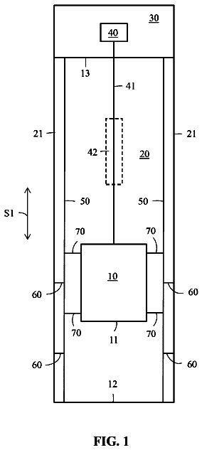
A system is provided for damping vertical oscillations of an elevator car stopped at an elevator landing.
US 9,828,215 B2 · Assignee: KONE CORPORATION · Inventors: Pelto-Huikko; Raimo
Sheet 1 of 5 from the published document. All sheets in the USPTO PDF
A rope for a hoisting device, which rope is belt-shaped and includes several load bearing members spaced apart in the width direction of the belt-shaped rope and embedded in a common coating, each of the load bearing members including several load bearing strings twisted together. The load bearing strings are made of composite material including reinforcing fibers embedded in polymer matrix.
An elevator typically comprises a hoisting roping suspending a vertically movable elevator car. The elevator further comprises a drive machine which drives the elevator car under control of an elevator control system. The driving force is typically transmitted from the drive machine to the car via said hoisting roping. The drive machine typically comprises a motor and a drive wheel engaging the individual ropes of the hoisting roping each of the ropes passing around the drive wheel and being connected to the car. The material and overall structure of the rope affects several properties of the rope, which are important for the elevator. In particular, the minimal bending radius of the rope, the weight of the rope, the force transmission ability of the rope as such, as well as the force transmission ability via the engagement between the rope and the drive wheel are all affected by the mat
1 of 5 drawing sheets so far from the published document, cropped to the drawing. Every sheet is in the USPTO PDF.
What the patent claimed, word for word. All of it is now free to use.
The invention relates to a rope of a hoisting device, in particular to a rope of an elevator meant for transporting passengers and/or goods.
An elevator typically comprises a hoisting roping suspending a vertically movable elevator car. The elevator further comprises a drive machine which drives the elevator car under control of an elevator control system. The driving force is typically transmitted from the drive machine to the car via said hoisting roping. The drive machine typically comprises a motor and a drive wheel engaging the individual ropes of the hoisting roping each of the ropes passing around the drive wheel and being connected to the car. The material and overall structure of the rope affects several properties of the rope, which are important for the elevator. In particular, the minimal bending radius of the rope, the weight of the rope, the force transmission ability of the rope as such, as well as the force transmission ability via the engagement between the rope and the drive wheel are all affected by the material and overall structure of the rope. These properties affect the properties of the complete elevator. In particular, the minimal bending radius of the rope is important as it sets a lower limit for the radius of the wheels around which the rope passes in the elevator.
A large bending radius may reduce the space efficiency of the elevator as well as make the layout of the elevator more complicated. The drive wheel may also be necessary to be designed with a radius larger than optimal in terms of torque production and rotational speed. Heavy weight of each rope and the overall weight of the roping reduces energy efficiency of the elevator. The force transmission ability of each rope should therefore be as great as possible relative to the weight of the rope. These properties have been optimized in the rope as disclosed in international patent application WO2009090299 A1 for instance. In this particular case, a wide surface is provided for the rope which facilitates firm engagement with a drive wheel. The surface material is elastomeric, which provides protection for the rope inner parts and/or high friction thereby facilitating firm engagement with a drive wheel.
A problem with the solutions according to prior art is that it is difficult to form a rope which has a high load bearing ability (in particular tensile strength) relative to weight of the rope while at the same time making the rope bendable with a reasonably small bending radius and yet having a surface enabling good protection for the inner parts and/or good force transmitting abilities via the surface.
The object of the invention is, inter alia, to solve previously described drawbacks of known solutions and problems discussed later in the description of the invention. The object of the invention is to introduce a new rope as well as an elevator having a new rope, which rope is such that it has a high load bearing ability relative to weight of the rope while at the same time bendable with a reasonably small bending radius and yet having a surface enabling protection for the inner parts and/or good force transmitting abilities via the surface. Embodiments are presented, inter alia, where a high load bearing ability relative to weight is facilitated such that the rope has a large total cross-sectional area of the load bearing members relative to the total cross-sectional area of the parts of the rope not bearing load thereby minimizing the additional weight caused to the rope by the non-bearing parts of the rope.
It is brought forward a new rope for a hoisting device, in particular for an elevator, which rope is belt-shaped and comprises several parallel load bearing members spaced apart in the width direction of the belt-shaped rope and embedded in a common coating. Each of the load bearing members comprises several load bearing strings twisted together, which load bearing strings are each made of composite material comprising reinforcing fibers embedded in polymer matrix. Thus, one or more of the objects of the invention are achieved. In particular, thus a rope can be obtained which has a high load bearing ability (in particular tensile strength provided largely by the reinforcing fibers) relative to weight of the rope while at the same time making the rope bendable with a reasonably small bending radius and yet having a surface enabling good protection for the inner parts and/or good force transmitting abilities via the surface. The coating also enables combining the load-bearing strings to form a cross-section which can facilitate using only small amounts of coating material.
In a preferred embodiment one or more, preferably each, of said load bearing members has at least one at least substantially flat outer side face covered by said coating with at least substantially constant material thickness. The portion of the coating positioned against the flat outer side face of the load bearing members thereby has a flat outer side face extending parallelly with the flat outer side face of the load bearing member, which flat outer side face forms a portion of the outer surface of the rope in question. By coating a flat face, the thickness of the coating can be kept small in amount simply for the whole area of the coated face. The amount of material of the coating can in this way be easily be minimized, which is advantageous both for the sake of reducing unnecessary material use but importantly for reducing the total weight of the rope. In fact, it is preferable that at least some of the load bearing members of the rope comprises at several at least substantially flat outer side faces covered by said coating with at least substantially constant material thickness. Thereby, the thickness of the coating is minimized on more than one side of said at least some load bearing members, whereby said advantage is increased.
In a preferred embodiment, one or more, preferably each, of said load bearing members of the rope has at least one at least substantially flat outer side face extending in width direction of the belt-shaped rope. Thus, the cross-sectional area of the rope can be efficiently utilized for load bearing function while keeping the thickness of the rope small. Also, the thickness of the coating positioned against the flat outer side face can thus be small in amount and thereby the amount of material of the coating can in this way be easily be minimized, which is advantageous both for the sake of reducing unnecessary material use but importantly for reducing the total weight of the rope.
In a preferred embodiment, one or more, preferably each, of said load bearing members has plurality of at least substantially flat outer side faces. This is advantageous for the purpose of more efficient usage of the cross section of the rope. In particular, the material thickness of the common coating can in this way be formed thin in several points. Thereby, the weight addition caused on the rope by the coating can be minimized. This can be obtained with an embodiment where each of said load bearing members has rectangular or triangular or pentagonal or hexagonal cross-sectional shape.
In a preferred embodiment, one or more, preferably each, of said load bearing members has four at least substantially flat outer side faces. This is advantageous for the purpose of more efficient usage of the cross section of the rope. In particular, the material thickness of the common coating can in this way be formed thin in several points. Thereby, the weight addition caused on the rope by the coating can be minimized.
In a preferred embodiment, one or more, preferably each, of said load bearing members is at least substantially rectangular in cross section. The load bearing parts of this shape are easy to place close to each other and/or the surface of the rope (i.e. coated with small material thickness), when compared with load bearing parts of round cross section for instance. This structure is advantageous as the cross-sectional area of the rope can be efficiently utilized for load bearing function. Also, the amount of material of the coating can in this way be minimized, which is advantageous both for the sake of reducing unnecessary material use but importantly for reducing the total weight of the rope. In a further refined embodiment each of said load bearing members is at least substantially quadratic in cross section. In this way the load bearing strings can easily be shaped to have closely same size and shape in cross section with each other.
In a preferred embodiment, one or more, preferably each, of said load bearing members has rounded corners. Thus, the outer corners of the load bearing members as well as the inner corners of the coating can be protected from wear and fractures.
In a preferred embodiment the rope has a contoured side surface provided with grooves oriented in the longitudinal direction of the rope, including grooves positioned in width direction of the rope centrally between adjacent load bearing members. Thus, the coating is at its thickest at the point of the load bearing member, and thinnest at the point of the gap between adjacent load bearing members. This is advantageous inter alia, because the load bearing members can be protected with minimal thickness of coating, which is important for facilitating a light total weight of the rope.
In a preferred embodiment the rope has a contoured side surface provided with grooves oriented in the longitudinal direction of the rope, including grooves of a first depth positioned in width direction of the rope centrally between adjacent load bearing members and grooves of a second depth positioned in width direction of the rope at the point of a load bearing member, the second depth being smaller than the first depth. Thus, a dense groove pattern can be provided with only thin amount of coating, yet the coating is not excessively thin at the point of the load bearing members thereby still being capable of providing sufficient means for protection and/or force transmission. These functions can be then provided with minimal thickness of coating which is important for facilitating a light total weight of the rope. In use in an elevator arrangement said contoured side is preferably fitted to pass against a contoured circumference of a drive wheel forming a counterpart for said contoured side of the rope, which circumference is provided with ribs, a rib extending into each of said grooves of the rope.
In a preferred embodiment said load bearing strings are twisted around a center string. The center string is preferably also a load bearing composite string. The center string is preferably parallel with the longitudinal direction of the load bearing member as well as with the longitudinal direction of the rope. It has preferably a round cross section.
In a preferred embodiment at least one layer of said load bearing strings surrounds the center string the innermost layer leaning against the center string. The strings of the layer are in helical formation around the center string.
In a preferred embodiment each load bearing string of said layer has a wedge shaped cross section (tapering towards the center of the load bearing member).
In a preferred embodiment each of the load bearing members of the innermost layer has a side face via which it leans against the center string, the face having a concave shape forming a counterpart for a convex shape of the center string.
In a preferred embodiment individual load bearing strings comprise a thin polymer coating around it isolating the string in question from the load bearing strings next to it.
In a preferred embodiment said load bearing members are parallel with the longitudinal direction of the rope. Thereby, the load bearing members are oriented in the direction of the force when the rope is pulled, which gives the rope a high tensile stiffness and strength.
In a preferred embodiment said reinforcing fibers are parallel with the longitudinal direction of the load bearing string. In particular, the reinforcing fibers of the same load bearing string are preferably essentially untwisted in relation to each other. Thereby, the reinforcing fibers are oriented in the direction of the force when the string in question is pulled, which gives the strings a high tensile stiffness and strength.
In a preferred embodiment said reinforcing fibers are carbon fibers. Carbon fibers are both lightweighted and own good tensile properties, in particular tensile strength and stiffness. Thus, they suit well for use to provide the load bearing ability for a rope of a hoisting device.
Preferably, individual reinforcing fibers are homogeneously distributed in said polymer matrix. Preferably, over 50% of the cross-sectional area of the load bearing string consists of said reinforcing fiber.
In a preferred embodiment said common coating is made of elastomeric material, such as silicon or substantially silicon-based material or polyurethane or substantially polyurethane-based material. Elastomeric material, in particular the aforementioned materials, provide protection for the load bearing members. Also, the coating made of such material can efficiently be utilized as a media for transmitting external forces to the load bearing members.
In a preferred embodiment the load bearing members of the rope cover together majority, preferably 70% or over, more preferably 75% or over, most preferably 80% or over, most preferably 85% or over, of the width of the cross-section of the rope. In this way at least majority of the width of the rope will be effectively utilized and the rope can be formed to be light and thin in the bending direction for reducing the bending resistance.
In a preferred embodiment the module of elasticity (E) of the polymer matrix is over 2 GPa, most preferably over 2.5 GPa, yet more preferably in the range 2.5-10 GPa, most preferably of all in the range 2.5-3.5 GPa. In this way a structure is achieved wherein the matrix essentially supports the reinforcing fibers, in particular from buckling. One advantage, among others, is a longer service life. The turning radius in this case is, formed so large that the above defined measures for coping with large turning diameter are especially advantageous.
It is also brought forward a new elevator comprising a vertically movable elevator car and a roping suspending the car, the roping comprising at least one rope. The roping comprises at least one rope, preferably several of them, which are as described above or elsewhere in the application. Thus, an elevator is achieved, which has, thanks to the tensile properties provided by the fibers of the rope a potential for good energy efficiency, as well as high lifting capacity. Thanks to its good bending properties the rope is drivable with a small radius drive wheel. This makes it possible to design the drive wheel to have a high rotational speed if needed and/or provides freedom to choose the drive wheel structure more freely. The roping layout can also more freely be formed simple in terms of its route involving one or more turns around diverting and/or drive wheel(s) of the elevator.
Preferably, the elevator further comprises a drive machine which drives the elevator car under control of an elevator control system, in particular as a response to calls from passengers. Preferably, the drive machine comprises a a drive wheel, which engages the rope(s) of said roping. The rope(s) of the roping pass around the drive wheel in such particular way that the wide side of each rope rests against the circumference of the drive wheel. Thus, driving force can be effectively transmitted from the motor to the car and preferably also to said counterweight via the drive wheel and the roping so as to move the car, and preferably also counterweight if the elevator comprises one. Preferably, the elevator comprises a vertically movable counterweight interconnected with the car and suspended by said roping. Then, the rope(s) of the roping pass around the drive wheel and suspend the elevator car and preferably also a counterweight on opposite sides of the drive wheel.
The elevator as describe anywhere above is preferably, but not necessarily, installed inside a building. The car is preferably arranged to serve two or more landings. The car preferably responds to calls from landing(s) and/or destination commands from inside the car so as to serve persons on the landing(s) and/or inside the elevator car. Preferably, the car has an interior space suitable for receiving a passenger or passengers.
In the following, the present invention will be described in more detail by way of example and with reference to the attached drawings, in which
FIGS. 1 a to 1 l illustrate alternative preferred cross sections of the rope.
FIG. 2 illustrates a preferred internal structure for the load bearing member.
FIG. 3 a illustrates the rope of FIG. 1 a three-dimensionally.
FIG. 3 b illustrates partly an enlarged view of the cross section illustrated in FIGS. 1 a and 3 a.
FIG. 4 illustrates preferred embodiment of an elevator.
FIGS. 1 a to 1 g illustrate each a cross-section of an embodiment of a rope 11 , 12 , 13 , 14 , 15 , 16 , 17 , 18 , 19 , 20 , 21 , 22 which rope is belt-shaped and thereby has width larger than thickness as measured in transverse direction of the rope 11 , 12 , 13 , 14 , 15 , 16 , 17 , 18 , 19 , 20 , 21 , 22 . The rope 11 , 12 , 13 , 14 , 15 , 16 , 17 , 18 , 19 , 20 , 21 , 22 comprises several elongated load bearing members 10 , 10 ′, 10 ″, 10 ′″, 10 ″″, 10 ′″″, 10 ″″″ spaced apart in the width direction of the belt-shaped rope 11 - 22 positioned adjacently on a same plane and extending parallel with the longitudinal direction of the rope 11 - 22 . The load bearing members 10 , 10 ′, 10 ″, 10 ′″, 10 ″″, 10 ′″″, 10 ″″″ are embedded in a coating 30 common for them all, which coating 30 forms the surface of the rope 11 - 22 . The coating 30 binds the load bearing members 10 , 10 ′, 10 ″, 10 ′″, 10 ″″, 10 ′″″, 10 ″″″ together separating them from each other, which provides the advantage of protection against chafing of individual load bearing members 10 , 10 ′, 10 ″, 10 ′″, 10 ″″, 10 ′″″, 10 ″″″ against each other, as well as the advantage of accurate positioning of the load bearing members 10 , 10 ′, 10 ″, 10 ′″, 10 ″″, 10 ′″″, 10 ″″″ relative to each other. Each of the load bearing members 10 , 10 ′, 10 ″, 10 ′″, 10 ″″, 10 ′″″, 10 ″″″ comprises several load bearing strings 1 , 1 ′, 1 ″, 1 ′″, 1 ″″, 1 ′″″, 1 ″″″. Each of said load bearing strings 1 , 1 ′, 1 ″, 1 ′″, 1 ″″, 1 ′″″, 1 ″″″, 1 ′″, 1 ″″, 1 ′″″, 1 ″″″ is made of composite material comprising reinforcing fibers f embedded in polymer matrix m as illustrated in FIG. 2 . The individual fibers f of each of said load bearing string 1 , 1 ′, 1 ″, 1 ′″, 1 ″″, 1 ′″″, 1 ″″″, 1 ′″, 1 ″″, 1 ′″″, 1 ″″″ are thereby bound to each other with the polymer matrix m so that these together form a uniform load bearing composite string 1 , 1 ′, 1 ″, 1 ′″, 1 ″″, 1 ′″″, 1 ″″″, 1 ′″, 1 ″″, 1 ′″″, 1 ″″″. Thus, each composite string 1 , 1 ′, 1 ″, 1 ′″, 1 ″″, 1 ′″″, 1 ″″″ is one solid elongated rodlike piece. The load bearing composite strings 1 , 1 ′, 1 ″, 1 ′″, 1 ″″, 1 ′″″, 1 ″″″, 1 ′″, 1 ″″, 1 ′″″, 1 ″″″ of each load bearing member 10 , 10 ′, 10 ″, 10 ′″, 10 ″″, 10 ′″″, 10 ″″″ are twisted together in the manner as illustrated three-dimensionally in FIG. 3 a . Said strings 1 , 1 ′, 1 ″, 1 ′″, 1 ″″, 1 ′″″, 1 ″″″ are thus in helical formation. For the sake of conciseness, only the rope 11 of FIG. 1 a is illustrated in this three-dimensional way. The composite strings 1 of each load bearing member 10 , 10 ′, 10 ″, 10 ′″, 10 ″″, 10 ′″″, 10 ″″″ are each load bearing elements of the load bearing member 10 , 10 ′, 10 ″, 10 ′″, 10 ″″, 10 ′″″, 10 ″″″.
The belt-shaped form gives the rope 11 - 22 a wide surface via which traction can be transmitted to the rope 11 - 22 , as well as a thin cross-section which makes the rope 11 - 22 easily bendable. The bending direction of each rope 11 - 22 is around an axis that is in the width direction of the rope 11 - 22 (up or down in the FIGS. 1 a to 1 l ). The fiber-reinforced composite material of the strings 1 , 1 ′, 1 ″, 1 ′″, 1 ″″, 1 ′″″, 1 ″″″ is light-weighted and has good tension bearing properties. A fiber-reinforced composite material is, however, relatively brittle and thereby difficult to bend sharply without risks of fractures in the composite material. The disadvantages of this material characteristic are minimized by the particular layout of internal structural parts of the rope as illustrated in FIGS. 1 a to 1 l . The twisted structure facilitates bending properties of the rope 11 - 22 , because the strings 1 , 1 ′, 1 ″, 1 ′″, 1 ″″, 1 ′″″, 1 ″″″ can straighten and slightly reorganize during bending. Thereby, the rope 11 - 22 can be provided with a small bending radius without reducing the thickness of the individual load-bearing parts 10 , 10 ′, 10 ″, 10 ′″, 10 ″″, 10 ′″″, 10 ″″″ (as measured in thickness direction of the rope) to a great extent. Forming the load bearing members 10 , 10 ′, 10 ″, 10 ′″, 10 ″″, 10 ′″″, 10 ″″″ of twisted composite strings can thereby provide the rope 11 - 22 a great bearing cross-sectional area. Thereby, the cross-section of the rope 11 - 22 can be utilized for load bearing function effectively. The proportion that the coating 30 forms of the total weight of the rope can thus be reduced. Thereby, the total weight of the rope 11 - 22 can be utilized for load bearing function effectively.
Said reinforcing fibers f are most preferably carbon fibers, as they are both lightweighted and own good tensile properties, in particular tensile strength and stiffness. Thus, they suit well for use to provide the load bearing ability for a rope of a hoisting device. However, alternatively other reinforcing fibers can be used instead of carbon fibers. Especially, glass fibers are found to be suitable for elevator use, their advantage being that they are cheap and have good availability although a mediocre tensile stiffness. The reinforcing fibers f are most preferably as far as possible parallel with the longitudinal direction of the string 1 , 1 ′, 1 ″, 1 ′″, 1 ″″, 1 ′″″, 1 ″″″ and therefore at least essentially untwisted in relation to each other. Thereby, the reinforcing fibers f are oriented in the direction of the force when the string in question is pulled. Thereby, the strings 1 , 1 ′, 1 ″, 1 ′″, 1 ″″, 1 ′″″, 1 ″″″ have good tensile stiffness and strength.
The twisted structure of the load bearing members 10 , 10 ′, 10 ″, 10 ′″, 10 ″″, 10 ′″″, 10 ″″″ is in the preferred embodiments such that several load bearing composite strings 1 , 1 ′, 1 ″, 1 ′″, 1 ″″, 1 ′″″, 1 ″″″ are twisted around a center string, which is parallel with the longitudinal direction of the rope 11 - 22 . The center string is preferably also a load bearing composite strings 1 , 1 ′, 1 ″, 1 ′″, 1 ″″, 1 ′″″, 1 ″″″ made of composite material comprising reinforcing fibers f in polymer matrix m, and has thereby corresponding structure and properties as the composite strings 1 , 1 ′, 1 ″, 1 ′″, 1 ″″, 1 ′″″, 1 ″″″ twisted around it. In the preferred embodiment at least one layer of said load bearing composite strings 1 , 1 ′, 1 ″, 1 ′″, 1 ″″, 1 ′″″, 1 ″″″ surrounds the center string the innermost layer leaning against the center string. The strings 1 , 1 ′, 1 ″, 1 ′″, 1 ″″, 1 ′″″, 1 ″″″ of this layer are in helical formation around the center string. In the embodiment as presented in FIGS. 1 a and 1 b , there is one such layer around the center string and in the embodiment as presented in each of FIGS. 1 c to 1 g , there are two of such layers around the center string, and innermost layer surrounding the center string and an outermost layer surrounding the innermost layer. Each string 1 , 1 ′, 1 ″, 1 ′″, 1 ″″, 1 ′″″, 1 ″″″ of said layer(s) has a wedge shaped cross section, which makes it possible that the strings are densely positioned within the cross-section of the load bearing member 10 , 10 ′, 10 ″, 10 ′″, 10 ″″, 10 ′″″, 10 ″″″. The term wedge-shaped means that the wires are on average tapered in terms of the dimensions of their cross-section, in particular towards the centerline of the rope. In these preferred embodiments, the strings of the innermost layer has a side face via which it leans against the center string, the face having a concave shape forming a counterpart for a convex shape of the center string. It is preferable, but not necessary, that individual strings 1 , 1 ′, 1 ″, 1 ′″, 1 ″″, 1 ′″″, 1 ″″″ comprise a thin polymer coating (not shown) around it isolating the string 1 , 1 ′, 1 ″, 1 ′″, 1 ″″, 1 ′″″, 1 ″″″ in question from the strings 1 , 1 ′, 1 ″, 1 ′″, 1 ″″, 1 ′″″, 1 ″″″ next to it. This allows better movement of the strings 1 , 1 ′, 1 ″, 1 ′″, 1 ″″, 1 ′″″, 1 ″″″ in relation to each other, because polymer can be selected to have such advantageously small friction properties that the films surrounding adjacent strings 1 , 1 ′, 1 ″, 1 ′″, 1 ″″, 1 ′″″, 1 ″″″ move against each other as the load bearing member 10 , 10 ′, 10 ″, 10 ′″, 10 ″″, 10 ′″″, 10 ″″″ bends. No essential wear caused by abrasion occurs between the composite strings 1 , 1 ′, 1 ″, 1 ′″, 1 ″″, 1 ′″″, 1 ″″″. This lengthens the service life of the rope 11 - 22 . The center string has preferably a round cross section thereby allowing slight and unobstructed movement of the strings 1 , 1 ′, 1 ″, 1 ′″, 1 ″″, 1 ′″″, 1 ″″″ leaning against it.
The aforementioned common coating 30 is preferably made of elastomeric material, such as polyurethane or substantially polyurethane-based material. Alternatively, it may be made of some other elastomeric material, such as silicon or substantially silicon based-material. Elastomeric material, in particular the aforementioned materials, provide protection for the load bearing members 10 , 10 ′, 10 ″, 10 ′″, 10 ″″, 10 ′″″, 10 ″″″. Also, the coating 30 made of such material can efficiently be utilized as a media for transmitting external forces to the load bearing members 10 , 10 ′, 10 ″, 10 ′″, 10 ″″, 10 ′″″, 10 ″″″.
Each of the load bearing members of the rope 11 - 22 has preferably a rectangular or a round or triangular or pentagonal or hexagonal cross-sectional shape. Embodiments with load bearing members 10 , 10 ′ of the round cross-sectional shape are illustrated in FIGS. 1 a to 1 d . Embodiments with load bearing members 10 ″ of the rectangular cross-sectional shapes in FIGS. 1 e to 1 g and 1 j . Embodiments with load bearing members 10 ′″, 10 ″″ of the hexagonal cross-sectional shapes in FIGS. 1 h and 1 i . Embodiment with load bearing members 10 ′″″ of the triangular cross-sectional shapes is illustrated in FIG. 1 k . Embodiment with load bearing members 10 ″″″ of the pentagonal cross-sectional shape is illustrated in FIG. 1 l.
In the preferred embodiments as illustrated in FIGS. 1 a to 1 d and 1 h to 1 l each of said load bearing members 10 , 10 ′, 10 ″, 10 ′″, 10 ″″, 10 ′″″, 10 ″″″ comprises at least one flat side face covered by said coating 30 with constant material thickness. The portion of the coating 30 positioned against the flat outer side face of the load bearing members 10 , 10 ′, 10 ″, 10 ′″, 10 ″″, 10 ′″″, 10 ″″″ thereby has a flat outer side face extending parallelly with the flat outer face of the load bearing member load bearing members 10 , 10 ′, 10 ″, 10 ′″, 10 ″″, 10 ′″″, 10 ″″″, which outer side face forms a portion of the outer surface of the rope in question. In this way, the thickness of the coating 30 positioned against the flat outer side face can thus be small in amount and thereby the amount of material of the coating 30 can in this way be easily be minimized, which is advantageous both for the sake of reducing unnecessary material use but importantly for reducing the total weight of the rope. In fact, it is preferable that at least some of the load bearing members 10 , 10 ′, 10 ″, 10 ′″, 10 ″″, 10 ′″″, 10 ″″″ of the rope comprises several flat outer side faces covered by said coating 30 with constant material thickness. Thereby, the thickness of the coating 30 is minimized on more than one side of said at least some load bearing members 10 , 10 ′, 10 ″, 10 ′″, 10 ″″, 10 ′″″, 10 ″″″, whereby said advantage is increased. The flat outer side faces of the load bearing member(s) as well as of the rope(s) is/are visible in the drawings 1 a to 1 l , 3 a and 3 b where they are drawn as straight edge-lines of the cross-section of the load bearing member/rope.
In the preferred embodiments as illustrated in FIGS. 1 a to 1 d , 1 h , 1 i , 1 k and 1 l each of the load bearing members 10 , 10 ′, 10 ″, 10 ′″, 10 ″″, 10 ′″″, 10 ″″″ of the rope 11 - 14 , 18 , 19 , 21 , 22 has at least one flat outer side face extending in width direction of the belt-shaped rope 11 - 14 , 18 , 19 , 21 , 22 . Thus, the cross-sectional area of the rope 11 - 14 , 18 , 19 , 21 , 22 can be efficiently utilized for load bearing function while keeping the thickness of the rope small. In particular, the thickness of the coating 30 positioned against the flat outer side face can thus be small in amount and thereby the amount of material of the coating 30 can in this way be easily be minimized, which is advantageous both for the sake of reducing unnecessary material use but importantly for reducing the total weight of the rope.
Advantageously, for the purpose of more efficient usage of the cross section of the rope 11 , 12 , 13 , 14 for load bearing function, it is preferable that each of said load bearing members 10 , 10 ′ has four flat outer side faces. For this purpose, in the preferred embodiments as illustrated in FIGS. 1 a to 1 d each of said load bearing members 10 , 10 ′ the rope 11 , 12 , 13 , 14 is further rectangular in cross section. Each of the load bearing members 10 , 10 ′ thus comprises flat outer side faces extending in thickness direction of the belt-shaped rope 11 - 14 . In particular, the outer side faces of adjacent load bearing members 10 , 10 ′ facing against each other are flat and parallel. The gaps between the adjacent load bearing members 10 , 10 ′ can in this way be formed narrow for the whole length of the gap as measured in thickness direction of the rope. Thus, the load bearing parts can be positioned close to each other with gap between them, which gap is narrow for the whole length of the gap as measured in thickness direction of the rope, but also the thickness of the coating 30 located between the surface of the rope 11 , 12 , 13 , 14 and the load bearing member 10 , 10 ′ can be easily made thin for the whole width of the load bearing member 10 , 10 ′. The corners of the load bearing members 10 , 10 ′ are preferably rounded as illustrated, as sharp edges placed against the coating 30 could damage the coating 30 . It is preferable that each of said load bearing members 10 , 10 ′ is at least substantially quadratic in cross section as in this way the strings 1 , 1 ′ can easily be shaped at least substantially similar cross section with each other. Thus, they need not be shaped to have a very sharp wedge shape, which would be harmful for endurance of the sharp edge of the string in question.
In the preferred embodiments as illustrated in FIGS. 1 b ,1 d ,1 e to 1 l , the rope 12 , 14 , 15 - 22 comprises a contoured side surface provided with grooves 32 , 34 , 36 , 37 , 38 , 41 , 42 , 44 , 46 , 48 oriented in the longitudinal direction of the rope 12 , 14 , 15 - 22 . The coating 30 forms the outer surface of the grooves 32 , 34 , 36 , 37 , 38 , 41 , 42 , 44 , 46 , 48 as well as the outer surface of the rest of the rope 12 , 14 , 15 - 22 . The grooves 32 , 34 , 36 , 37 , 38 , 41 , 42 , 44 , 46 , 48 of the surface of the rope 12 , 14 , 15 - 22 can be used to provide one or more of several technical advantages. The grooves can be used for making the engagement of the rope with a drive wheel firmer. In addition or alternatively they can be utilized for making the rope easier to flex away from flat form to a slightly curved form, especially when the grooves are positioned in width direction of the rope centrally between adjacent load bearing members. In addition or alternatively they can be utilized for, reducing the total weight of the coating 30 .
The ropes 12 , 14 , 16 , 17 , 20 - 22 as illustrated in FIGS. 1 b ,1 d ,1 f ,1 g ,1 j ,1 k or 1 l have deep grooves and are thereby particularly suitable to be used in an elevator arrangement, such that the contoured side of the rope is fitted to pass against a contoured circumference of a drive wheel 51 forming a counterpart for said contoured side of the rope 12 , 14 , 16 , 17 , 20 , 22 , said circumference being provided with ribs, a rib extending into each of said grooves 32 , 34 , 36 , 37 , 38 , 44 , 46 , 48 of the rope 12 , 14 , 16 , 17 , 20 - 22 . This kind of matching contoured shapes are advantageous especially for making the engagement firm and less likely to slip neither in longitudinal direction nor in transverse direction of the rope.
The ropes 15 , 16 17 - 20 as illustrated in FIGS. 1 e , 1 f and 1 g -1 j comprises two contoured side surfaces provided with grooves 36 , 38 , 38 , 40 , 41 , 42 , 43 , 44 positioned in width direction of the rope 15 , 16 , 17 - 20 centrally between adjacent load bearing members 10 ″, 10 ″, 10 ′″, 10 ″″, 10 ′″″. Thus, the total weight of the coating 30 is reduced. Also, the rope 15 , 16 , 17 - 20 is hereby made easier to flex away from flat form to a slightly curved form. Thus it can be made to adjust easily against a cambered roller of the elevator system, which may then be used for guiding the rope 15 , 16 , 17 - 20 .
It is not necessary, however that the rope has a grooved surface. The wide sides of the belt-like rope can be for instance smooth as illustrated in FIGS. 1 a and 1 c . When the rope 11 , 13 as illustrated in FIGS. 1 a and 1 c is used in an elevator arrangement, then also the surface of the drive wheel 51 is preferably smooth. In that case, each of said rope 11 , 13 has a wide and smooth side without guide ribs or guide grooves or teeth, which may be in use fitted to pass against a smooth circumference of the drive wheel, which circumference is possibly but not necessarily slightly cambered.
The preferred details of the preferred embodiments of the rope are explained more specifically in the following. In the preferred embodiments illustrated in FIG. 1 b , 1 d ,1 f ,1 g ,1 j ,1 k ,1 l , the rope 12 , 14 , 16 , 17 , 20 , 21 , 22 comprises bars 31 , 33 , 35 , 39 , 45 , 47 , 49 oriented in the longitudinal direction of the rope 12 , 14 , 16 , 17 , 20 , 21 , 22 and grooves 32 , 34 , 36 , 37 , 38 , 44 , 46 , 48 oriented in the longitudinal direction of the rope formed between the bars 31 , 33 , 35 , 39 , 45 , 47 , 49 . In embodiments of FIGS. 1 b and 1 e to 1 l the grooves 32 , 34 , 36 , 37 , 38 , 41 , 42 , 44 , 46 , 48 include grooves 32 , 36 , 37 , 38 , 41 , 42 , 44 , 46 , 48 positioned in width direction of the rope 12 , 16 , 17 , 20 , 21 , 22 centrally between adjacent load bearing members 10 , 10 ″, 10 ′″, 10 ″″, 10 ′″″, 10 ″″″ and the bars 31 , 33 , 35 , 39 , 45 , 47 , 49 include bars 31 , 35 , 45 , 47 , 49 positioned in width direction of the rope 12 , 16 , 17 , 20 , 21 , 22 centrally at the point of a load bearing member 10 , 10 ′″, 10 ″″, 10 ′″″, 10 ″″″. Thus, the coating is at its thickest at the point of the load bearing member 10 , 10 ′″, 10 ″″, 10 ′″″, 10 ″″″, and thinnest at the point of the gap between adjacent load bearing members 10 , 10 ′″, 10 ″″, 10 ′″″, 10 ″″″. Thereby, the load bearing members 10 , 10 ′″, 10 ″″, 10 ′″″, 10 ″″″ can be well protected with minimal thickness of coating 30 . In the preferred embodiment illustrated in FIG. 1 g the rope 17 comprises a contoured side surface provided with grooves 37 , 38 oriented in the longitudinal direction of the rope 17 , including grooves 37 of a first depth positioned in width direction of the rope 17 centrally between adjacent load bearing members 10 ″ and grooves 38 of a second depth positioned in width direction of the rope 17 centrally at the point of a load bearing member 10 ″, the second depth being smaller than the first depth. Between each pair of successively adjacent (in width direction of the rope) grooves 37 and 38 there is a bar 39 . Said bars 39 extend mutually same distance from the width directional central plane of the rope 17 .
In the embodiments as illustrated in FIGS. 1 k and 1 l the load bearing members have a cross-sectional shape with an acute angle between adjacent flat outer side faces. In this case, it is especially beneficial that the rope 21 , 22 comprises a contoured side surface provided with grooves 46 , 48 oriented in the longitudinal direction of the rope, which grooves are positioned in width direction of the rope centrally between adjacent load bearing members 10 ′″″, 10 ″″″. Particularly preferably, the rope 21 , 22 comprises such grooves 46 , 48 which extend between the adjacent load bearing members 10 ′″″, 10 ″″″ With this structure a grooved rope surface is obtained with minimal use of coating material.
FIG. 4 illustrates an elevator according to a preferred embodiment. The elevator comprises a hoistway S, an elevator car C and a counterweight CW vertically movable in the hoistway S, the car C and counterweight CW being interconnected with rope(s) 11 - 22 of a roping R, which ropes 11 - 22 are described and illustrated elsewhere in the application. The elevator further comprises a drive machine M which drives the elevator car C under control of an elevator control system 10 . The drive machine M comprises a motor 50 and a drive wheel 51 . The drive wheel 51 engages an elevator roping R, which passes around the drive wheel 51 and suspends the elevator car C and the counterweight CW. Thus, driving force can be transmitted from the motor 30 to the car C and counterweight CW via the drive wheel 51 and the roping R so as to move the car C and counterweight CW.
As mentioned, the rope 11 - 22 is belt-shaped, particularly having two wide sides opposite each other. The width/thickness ratio of each rope 11 - 22 is preferably at least 2, more preferably at least 4. In this way a large cross-sectional area for the rope is achieved, the bending capacity around the width-directional axis being good also with rigid materials of the load bearing members. In the preferred embodiments, the load bearing members 10 , 10 ′, 10 ″, 10 ′″, 10 ″″, 10 ′″″, 10 ″″″ comprised in the rope together cover majority, preferably 70% or over, more preferably 75% or over, most preferably 80% or over, most preferably 85% or over, of the width of the cross-section of the rope 11 - 22 . The width of the rope 11 - 22 is thus efficiently utilized. Thus the supporting capacity of the rope with respect to its total lateral dimensions is good, and the rope does not need to be formed to be thick.
The description continues in the full USPTO document.
About 7,301 words. The USPTO PDF has it with every drawing.
Fees are due 3.5, 7.5 and 11.5 years after grant. This patent expired on November 28, 2025, so the fee marked "not paid" was the one that went unpaid.
ROPE FOR A HOISTING DEVICE AND ELEVATOR
Filed Sep 2014 · published Apr 2015Rope for a hoisting device and elevator
Filed Sep 2014 · granted Nov 2017Earlier publications, parents and continuations. None of them can still be enforced, or this patent would not be listed.
Prior art cited by the examiner or applicant. Useful when you check your own idea for novelty.
Everything on this page comes from the documents linked above.