Background
1. Technical field
The present invention relates to a three-dimensional formation apparatus.
2. Related art
In recent years, a three-dimensional formation apparatus using a printing technology has been paid attention. For example, an ink jet technology generally used in a printing technology is used in three-dimensional formation apparatuses disclosed in JP-A-06-218712, JP-A-2005-67138, and JP-A-2010-58519. In the three-dimensional formation apparatuses using an ink jet technology, a three-dimensional object is formed by performing a step of discharging liquid having curing properties and forming a cross section object for a layer along a horizontal direction (XY direction), over a plurality of layers in a height direction (Z direction).
In a predetermined formation resolution, the ink jet-type three-dimensional formation apparatus discharges liquid to predetermined coordinates and forms dots to form a cross section object. Accordingly, an outline parallel to an X or Y direction can be smoothly formed, but a deviation of coordinates between adjacent dots is generated regarding an outline inclined in the above directions, and jaggy is generated. Particularly, jaggy is easily noticed in a case where an angle inclined in the X or Y direction is an acute angle.
In a printing technology of a two-dimensional image, it is possible to prevent generation of jaggy by forming small dots, for example, in a portion where the deviation of coordinates is generated. However, when small dots are formed in a portion where the deviation of coordinates is generated in a case of forming a three-dimensional object, a height of the portion is decreased, and it is difficult to form an appropriate three-dimensional shape. Accordingly, it is difficult to simply apply the printing technology of a two-dimensional image to the formation process of a three-dimensional object. Thus, in the three-dimensional formation apparatus which discharges liquid and forms a three-dimensional object, it is necessary to obtain a technology which can effectively prevent generation of jaggy in an object to be formed.
Summary
The invention is realized in the following forms.
According to an aspect of the invention, there is provided a three-dimensional formation apparatus which forms a three-dimensional object, the apparatus including: a head unit which discharges liquid which is one material of the object in a first direction, among the first direction, a second direction, and a third direction orthogonal to each other; and a control unit which forms the object by laminating the plurality of cross section objects by executing a cross section object formation process of forming a cross section object for one layer of the object several times by discharging the liquid containing a first quantity to a designated coordinate among coordinates representing a position in the second direction and a position in the third direction, by controlling the head unit, in which the control unit forms the cross section object by discharging the liquid containing a second quantity which is smaller than the first quantity to a changed portion where an outline of the cross section object is simultaneously changed in the second direction and the third direction, in the first cross section object formation process among the cross section object formation processes executed several times, and executes a filling process of discharging the liquid containing a third quantity which exceeds the first quantity when the third quantity is added to the second quantity to a portion to which the liquid containing the second quantity is discharged, after the first cross section object formation process is executed and before the second cross section object formation process is executed. In this case, since the liquid containing the second quantity which is smaller than the normal quantity (first quantity) is discharged to the changed portion where the outline of the cross section object is simultaneously changed in the second direction and the third direction, a thickness thereof is decreased with respect to the other portions. Then, the liquid containing the quantity (third quantity) exceeding the first quantity when the third quantity is added to the second quantity is discharged to the thinner portion. Accordingly, the liquid containing the quantity exceeding the first quantity overflows to the outside of the cross section object from the thinner portion and fills a difference in level on the portion where the outline of the cross section object is simultaneously changed in the second direction and the third direction. Therefore, it is possible to effectively prevent generation of jaggy on the outline inclined in the second direction and the third direction.
The three-dimensional formation apparatus according to the aspect of the invention may further include a curing energy application unit which applies curing energy for curing the liquid, and the curing energy application unit may apply the curing energy to the discharged liquid, after the liquid is discharged in the first cross section object formation process and before the filling process is executed at an interval of a first time period, and may apply the curing energy to the discharged liquid, after the liquid is discharged in the filling process and before the second cross section object formation process is executed at an interval of a second time period which is longer than the first time period. In this case, since the curing energy is applied at the interval of the first time period after the liquid is discharged, in the cross section object formation processes, it is possible to suppress stain of the shape of the portion formed thinner than the other portions by discharging the liquid containing the second quantity among the cross section objects. Accordingly, it is possible to accurately discharge the liquid to the thinner portion, in the subsequent filling process. In addition, since the curing energy is applied at the interval of the second time period which is longer than the first time period, after discharging the liquid to the thinner portion, it is possible to sufficiently apply the time only for filling the difference in level with the curable liquid. Therefore, it is possible to more effectively prevent the generation of jaggy on the outline.
In the three-dimensional formation apparatus according to the aspect of the invention, the coordinate to which the liquid is discharged in the cross section object formation process may have the element corresponding to each coordinate and may be designated by two-dimensional raster data in which a gradation value corresponds to each element, and the changed portion may be a portion where a second element adjacent to the inside of the first element on the second direction side or the third direction side in which the gradation value is less than 100%, when a portion corresponding to the outline of the cross section object of the raster data is subjected to a smoothing process. In this case, since the liquid overflows to the outline portion corresponding to the portion in which the gradation value is less than 100% when the smoothing process of the raster data representing the cross section object is performed, it is possible to effectively prevent the generation of jaggy.
In the three-dimensional formation apparatus according to the aspect of the invention, the second quantity may be a quantity corresponding to the gradation value of the first element. In this case, it is possible to reliably decrease the thickness of the changed portion.
In the three-dimensional formation apparatus according to the aspect of the invention, the third quantity may be a quantity corresponding to the gradation value of the second element. In this case, it is possible to set the quantity of the liquid which overflows to the difference-in-level portion as an accurate quantity.
In the three-dimensional formation apparatus according to the aspect of the invention, the shape of the object may be represented with polygon data which is an assembly of a plurality of polygons, and the first element may be an element corresponding to a position where the polygon crosses. In this case, since the first element in which the gradation value is less than 100% in the smoothing process is determined based on whether or not the polygon representing the three-dimensional object crosses the element, it is possible to accurately specify the first element.
In the three-dimensional formation apparatus according to the aspect of the invention, the gradation value of the first element may be a value corresponding to a ratio of a volume remaining when a volume is cut by the polygon, to the volume of the first element occupying a three-dimensional space. In this case, it is possible to accurately calculate the gradation value of the first element in which the gradation value is less than 100% in the smoothing process.
In the three-dimensional formation apparatus according to the aspect of the invention, the second element may be an element adjacent to a direction of a large component among a component in the second direction and a component in the third direction of an inward normal line of the polygon which crosses the first element, among an element in the second direction adjacent to the first element and an element in the third direction adjacent to the first element. In this case, it is possible to accurately specify the portion to which the liquid containing the second quantity is discharged to decrease the thickness.
The invention can be realized in various forms, in addition to the aspects of the three-dimensional formation apparatus. For example, invention can be realized in forms of a three-dimensional formation method of forming a three-dimensional object by a three-dimensional formation apparatus, a computer program causing a computer to control a three-dimensional formation apparatus and form a three-dimensional object, and a non-primary recording medium in which the computer program is recorded.
Brief description of the drawings
The invention will be described with reference to the accompanying drawings, wherein like numbers reference like elements.
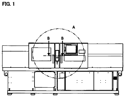
FIG. 1 is an explanatory diagram showing a schematic configuration of a three-dimensional formation apparatus.
FIG. 2 is a flowchart of a three-dimensional formation process.
FIG. 3 is a flowchart showing details of a smoothing process.
FIG. 4 is an explanatory diagram showing a positional relationship between a target element and a polygon.
FIGS. 5A to 5D are explanatory diagrams showing a method of forming main data and auxiliary data.
FIG. 6 is a diagram showing a concept of a second element.
FIGS. 7A to 7C are explanatory diagrams showing a state where a cross section object is formed by a head unit.
FIG. 8 is an explanatory diagram showing a specific controlling method of curing energy application units.
FIGS. 9A and 9B are explanatory diagrams showing a state where an outline portion of the cross section object is formed by curable liquid and a support material.
FIG. 10 is a flowchart showing a smoothing process of a third embodiment.
FIG. 11 is a flowchart showing a smoothing process of a fourth embodiment.
FIG. 12 is an explanatory diagram showing a schematic configuration of a three-dimensional formation apparatus of a fifth embodiment. DESCRIPTION OF EXEMPLARY EMBODIMENTS A. First Embodiment
FIG. 1 is an explanatory diagram showing a schematic configuration of a three-dimensional formation apparatus as a first embodiment. A three-dimensional formation apparatus 100 includes a formation unit 10 , a powder supply unit 20 , a flattening mechanism 30 , a powder collection unit 40 , a head unit 50 , curing energy application units 60 , and a control unit 70 . A computer 200 is connected to the control unit 70 . The three-dimensional formation apparatus 100 and the computer 200 can be collectively treated as a three-dimensional formation apparatus in a broad sense. FIG. 1 shows an X direction, a Y direction, and a Z direction orthogonal to each other. The Z direction is a direction along a vertical direction and the X direction is a direction along a horizontal direction. The Y direction is a direction vertical to the Z direction and the X direction. The Z direction corresponds to a first direction, the X direction corresponds to a second direction, and the Y direction corresponds to a third direction.
The formation unit 10 is a tank-shaped structure in which a three-dimensional object is formed. The formation unit 10 includes a formation stage 11 which is flat in the XY direction, a frame body 12 which surrounds around the formation stage 11 and stands in the Z direction, and an actuator 13 which moves the formation stage 11 along the Z direction. The formation stage 11 moves in the Z direction in the frame body 12 by the control unit 70 controlling an operation of the actuator 13 .
The powder supply unit 20 is an apparatus which supplies powder into the formation unit 10 . The powder supply unit 20 is, for example, configured with a hopper or a dispenser.
The flattening mechanism 30 is a mechanism for flattening powder supplied into the formation unit 10 or onto the frame body 12 by moving an upper surface of the formation unit 10 in the horizontal direction (XY direction), and forming a powder layer on the formation stage 11 . The flattening mechanism 30 is, for example, configured with a squeegee or a roller. The powder extruded from the formation unit 10 by the flattening mechanism 30 is discharged into the powder collection unit 40 provided adjacent to the formation unit 10 .
The three-dimensional formation apparatus 100 of the first embodiment uses liquid having curing properties (hereinafter, referred to as “curable liquid”) and the powder as the materials of the three-dimensional object. As the curable liquid, a mixture of a resin material of liquid having a monomer and an oligomer bound with the monomer as main components, and a polymerization initiator which turns into an excitation state and starts polymerization by promoting the monomer and the oligomer, when an ultraviolet light beam is emitted, is used. For the monomer in the curable liquid, a monomer having comparatively low molecular weight is selected so that a viscosity of the curable liquid is set as a low viscosity to be discharged dropwise from the head unit 50 , and the number of monomers contained in one oligomer is also approximately adjusted to several molecules. The curable liquid has properties to be rapidly cured to be solid by polymerizing the monomers with each other to grow the monomers to the oligomer or polymerizing some oligomers with each other, when the curable liquid is irradiated with the ultraviolet light beam and the polymerization initiator turns into an excitation state. In the embodiment, powder in which a polymerization initiator which is different from the polymerization initiator contained in the curable liquid is attached to the surface thereof is used as the powder. The polymerization initiator attached to the surface of the powder has properties of starting polymerization of the monomers or the oligomer by promoting it, when the polymerization initiator comes in contact with the curable liquid. Accordingly, when the curable liquid is supplied to the powder in the formation unit 10 , the curable liquid permeates the inside of the powder and comes in contact with the polymerization initiator on the surface of the powder to be cured. As a result, in a portion to which the curable liquid is discharged, the powders are bound by the cured curable liquid. When the powder having the polymerization initiator attached to the surface thereof is used as the powder, it is also possible to use curable liquid not containing the polymerization initiator.
The head unit 50 is an apparatus which receives the supply of the curable liquid from a tank 51 connected to the head unit 50 and discharges the curable liquid to a powder layer in the formation unit 10 along the Z direction. The head unit 50 can be moved in the X direction and the Y direction with respect to the three-dimensional object formed in the formation unit 10 . The head unit 50 can be moved in the Z direction relatively to the three-dimensional object by the formation stage 11 in the formation unit 10 which moves in the Z direction. The head unit 50 of the embodiment is a so-called piezoelectric driving type liquid droplet discharge head. By filling a pressure chamber provided with fine nozzle holes with the curable liquid and bending a side wall of the pressure chamber using a piezoelectric element, the piezoelectric driving type liquid droplet discharge head can discharge a volume of the curable liquid corresponding to a decreased amount of a volume of the pressure chamber as liquid droplets. Since the control unit 70 which will be described later controls a voltage waveform applied to the piezoelectric element, it is possible to adjust quantity of the curable liquid per droplet discharged from the head unit 50 in a stepwise manner. Nozzle holes through which the curable liquid is discharged, are arranged on the head unit 50 along the Y direction.
The curing energy application units 60 are apparatuses which apply energy for curing the curable liquid discharged from the head unit 50 . In the embodiment, the curing energy application units 60 are configured with a final curing light emitting apparatus 61 and a temporary curing light emitting apparatus 62 which are disposed so as to interpose the head unit 50 in the X direction. When the head unit 50 is moved, the curing energy application units 60 are also moved according to the movement thereof. The ultraviolet light beam is emitted from the final curing light emitting apparatus 61 and the temporary curing light emitting apparatus 62 as curing energy for curing the curing liquid. The temporary curing light emitting apparatus 62 is used in performing temporary curing for fixing the discharged curable liquid to a landed position thereof. The final curing light emitting apparatus 61 is used for completely curing the curable liquid after the temporary curing. The energy of the ultraviolet light beam emitted from the temporary curing light emitting apparatus 62 is energy of 20% to 30% of the ultraviolet light beam emitted from the final curing light emitting apparatus 61 , for example. The temporary curing is also referred to as “pinning” and the final curing is also referred to as “curing”.
The control unit 70 is an apparatus which controls the actuator 13 , the powder supply unit 20 , the flattening mechanism 30 , the head unit 50 , and the curing energy application units 60 and forms the three-dimensional object. The control unit 70 includes a CPU and a memory. The CPU realizes a cross section object formation function and a filling function by loading computer programs stored in a memory or a recording medium in the memory and executing the programs. The cross section object formation function is a function of controlling the head unit 50 and forming a cross section object for one layer of the three-dimensional object by discharging each of the curable liquid containing a first quantity to a designated coordinate among the coordinates in the X direction and the Y direction. In the cross section object formation function, the curable liquid containing a second quantity which is smaller than the first quantity is discharged to a changed portion where the outline of the cross section object is simultaneously changed in the X direction and the Y direction and the cross section object is formed. The filling function is a function of discharging the liquid containing a third quantity which exceeds the first quantity when it is added to the second quantity, to a portion to which the curable liquid containing the second quantity is discharged in the cross section object formation function. The specific process content for realizing these functions will be described later. These functions of the control unit 70 may also be applied to the computer 200 side.
A procedure of forming the three-dimensional object by the three-dimensional formation apparatus 100 will be simply described. First, the computer 200 slices three-dimensional data representing a shape of a three-dimensional object according to a formation in the Z direction (for example, 600 dpi) and generates a plurality of cross section data items along the XY direction. The cross section data items has a predetermined formation resolution (for example, 600 dpi×600 dpi) are represented as two-dimensional raster data in which a gradation value is stored with respect to each element. The gradation value stored with respect to each element represents the quantity of the curable liquid discharged to the XY coordinate corresponding to the element. That is, in the embodiment, the coordinate to which the curable liquid and the quantity of the curable liquid to be discharged are designated for the control unit 70 of the three-dimensional formation apparatus 100 by the raster data. For example, when the gradation value is designated as 100% with respect to a certain coordinate, a quantity of the curable liquid which can fill 100% of a volume of an element (voxel) in a three-dimensional space corresponding to the coordinate, is discharged from the head unit 50 . Herein, the quantity of the curable liquid per droplet discharged from the head unit 50 is limited to the finite kinds of quantity. Accordingly, when the gradation value is designated by the raster data, the control unit 70 makes the quantity of the curable liquid corresponding to the designated gradation value to the closest quantity among the predetermined kinds of quantity. For example, when the quantities of the curable liquid which can be discharged from the head unit 50 are five types of 0%, 25%, 50%, 75%, and 100%, the control unit 70 selects the quantity closest to the designated gradation value among the five types of quantity of the curable liquid. When the gradation value is designated, the control unit 70 may multiply a predetermined coefficient by the designated gradation value according to a curing shrinkage ratio of the curable liquid, for example.
When the cross section data is acquired from the computer 200 , the control unit 70 of the three-dimensional formation apparatus 100 controls the powder supply unit 20 and the flattening mechanism 30 and forms the powder layer in the formation unit 10 . The control unit drives the head unit 50 and discharges the curable liquid to the powder layer according to the cross section data, and then controls the curing energy application units 60 and emits the ultraviolet light beam towards the discharged curable liquid. By doing so, the curable liquid is cured and powders are bound with each other by the ultraviolet light beam, and the cross section object corresponding to the cross section data for one layer is formed in the formation unit 10 . When the cross section object for one layer is formed as described above, the control unit 70 drives the actuator 13 and moves the formation stage 11 downwards in the Z direction by an amount of a lamination pitch corresponding to the formation resolution in the Z direction. When the formation stage 11 is moved downwards, the control unit 70 forms a new powder layer on the cross section object which is previously formed on the formation stage 11 . When the new powder layer is formed, the control unit 70 receives a next cross section data item from the computer 200 , discharges the curable liquid to a new powder layer, and irradiates the new powder layer with the ultraviolet light beam, to form a new cross section object. As described above, when the cross section data of each layer is received from the computer 200 , the control unit 70 forms the cross section object for each layer and forms the three-dimensional object by laminating the layer, by controlling the actuator 13 or the powder supply unit 20 , the flattening mechanism 30 , the head unit 50 , and the curing energy application units 60 .
Next, the more specific process content of the three-dimensional formation process of the embodiment will be described.
FIG. 2 is a flowchart of the three-dimensional formation process executed by the computer 200 and the three-dimensional formation apparatus 100 . In the embodiment, first, the computer 200 acquires the three-dimensional data representing the shape of the three-dimensional object from a recording medium or a network, or an application program executed in the computer 200 (Step S 100 ). The three-dimensional data, for example, is represented as three-dimensional polygon data, two-dimensional raster data for each cross section, and two-dimensional vector data for each cross section. In the embodiment, the three-dimensional data is represented as the polygon data. When the three-dimensional data is acquired, the computer 200 performs the smoothing process (Step S 200 ).
FIG. 3 is a flowchart showing details of the smoothing process. In the smoothing process, the raster data for each cross section is generated from the three-dimensional data. First, the computer 200 cuts out one cross section having a thickness according to the formation resolution in the Z direction from the three-dimensional polygon data (Step S 202 ). When one cross section is cut out, the computer 200 specifies the element (coordinate) on the raster data for determining the gradation value in the following process (Step S 204 ). Hereinafter, this element is referred to as a “target element”.
When the target element is specified, the computer 200 determines whether or not there is a target element on the outside of the polygon (Step S 206 ). When it is determined that there is a target element on the outside of the polygon (Step S 206 : YES), the computer 200 determines the gradation value of the target element as 0% (Step S 208 ). When it is determined that there is not a target element on the outside of the polygon (Step S 206 : NO), the computer 200 further determines whether or not the polygon crosses the target element (Step S 210 ).
FIG. 4 is an explanatory diagram showing a positional relationship between the target element and the polygon. FIG. 4 shows a state where a polygon PL crosses a cubic lattice VX corresponding to the target element. In Step S 210 described above, when it is determined that the polygon crosses the target element as shown in FIG. 4 (Step S 210 : YES), the computer 200 calculates the gradation value of the target element based on the following equation
(Step S 212 ). Gradation value=maximum gradation value(100%)×polygon volume ratio
Herein, the polygon volume ratio is a ratio of a remaining volume VL in a case where a volume of the cubic lattice VX corresponding to the target element is cut out by the polygon, with respect to the volume thereof.
In Step S 210 described above, when it is determined that the polygon crosses the target element (Step S 210 : NO), the surface represented as the polygon and the surface on the outside of the cubic lattice represented as the target element coincide with each other, and accordingly, the computer 200 determines the gradation value of the target element as 100% (Step S 214 ).
When the gradation value of the target element is determined by the processes described above, the computer 200 determines whether or not the determination of the gradation value is completed regarding the entire element in the current cross section (Step S 216 ). When it is determined that the gradation value regarding the entire element in the current cross section is not determined (Step S 216 : NO), the process returns to Step S 204 and the computer 200 determines the gradation value regarding the other element.
When it is determined that the gradation value regarding the entire element in the current cross section is determined (Step S 216 : YES), the computer 200 determines whether or not the determination of the gradation value regarding the entire cross section is completed (Step S 218 ). When it is determined that the gradation value regarding the entire cross section is not completed (Step S 218 : NO), the process returns to Step S 202 and the computer 200 cuts out the next cross section and determines the gradation value regarding the entire element in the cross section. When it is determined that the gradation value regarding the entire element is completed (Step S 218 : YES), the computer 200 accommodates raster data in which the gradation value regarding the determined entire element is accommodated, in a memory or a recording medium, regarding the entire cross section as the cross section data (Step S 220 ), and the smoothing process is completed.
The description returns to FIG. 2 . When the smoothing process described above is completed, the computer 200 generates the main data and the auxiliary data based on the raster data accommodated in a memory by the smoothing process (Step S 300 ). The main data is data which is mainly used when the three-dimensional formation apparatus 100 forms the cross section object. The auxiliary data is data for refilling the curable liquid to a part of the cross section object formed using the main data.
FIGS. 5A to 5D are explanatory diagrams showing a method of generating the main data and the auxiliary data regarding one cross section by the computer 200 . FIG. 5A is a reference diagram showing an outline portion of the raster data when the smoothing process described above is performed. When the smoothing process described above is not performed, the gradation value of the raster data is represented as any one of 0% or 100%, and accordingly jaggy having a shape of a difference in level as shown in FIG. 5A is generated on the outline portion represented as the raster data. Particularly, jaggy is easily noticed in a case where an angle inclined in each of the X and Y directions is an acute angle. Meanwhile, when the smoothing process described above is not performed, the gradation value of the difference-in-level portion is represented as a half tone and the outline is smoothly represented, as shown in FIG. 5B . FIGS. 5A to 5D show an example where the gradation values are represented as five types of 0%, 25%, 50%, 75%, and 100%.
As shown in FIG. 5C , the computer 200 specifies first elements EL 1 in which the gradation value is less than 100%, and second elements EL 2 which are adjacent to the first elements EL 1 on the X direction side and the inside of the Y direction side, from the smoothed raster data represented as shown in FIG. 5B , replaces the gradation value of the second element EL 2 with the gradation value of the first element EL 1 , removes the gradation value of the first element EL 1 (sets as 0), and accordingly, generates the main data. As shown in FIG. 5D , the auxiliary data is generated from the original gradation value of the second element. In the example shown in FIGS. 5A to 5D , all of the gradation values of the second elements are 100% and are always greater than the gradation values of the first elements. The computer 200 determines whether or not the elements adjacent to the first elements EL 1 on both of the X direction side and the Y direction side are the second elements EL 2 , as described below.
FIG. 6 is a diagram showing a concept of a specifying method of the second element EL 2 . First, the computer 200 acquires an inward normal line AL of the polygon PL which crosses the first element EL 1 . An X component ALX and a Y component ALY of the normal line thereof are acquired, and the element adjacent to the direction of the component having a large value among the components (Y component ALY in a case of FIG. 6 ) is specified as the second element EL 2 . When the position of the second element EL 2 is specified as described above, it is possible to appropriately determine the position of the element for performing the replacement of the gradation value, with respect to the inclined outline.
The computer 200 generates the main data and the auxiliary data regarding each cross section by executing the process shown in FIGS. 5A to 5D regarding the entire cross sections. When the main data and the auxiliary data are generated, the computer 200 accommodates the data items in a memory or a recording medium regarding the entire cross sections as the cross section data items.
After the main data and the auxiliary data are generated regarding the entire cross sections by the computer 200 , the control unit 70 of the three-dimensional formation apparatus 100 acquires the cross section data items (the main data and the auxiliary data) representing the cross section of the lowest layer from the computer 200 (Step S 400 of FIG. 2 ). When the cross section data is acquired, the control unit 70 executes a cross section object formation process using the main data among the cross section data items thereof (Step S 500 ). The cross section object formation process is a process of discharging the curable liquid containing the first quantity to each coordinate in the X direction and the Y direction while moving the head unit 50 in the X direction and the Y direction, to form the cross section object which is a part of the three-dimensional object. The first quantity in the embodiment is a quantity corresponding to the 100% of the gradation value and is a quantity of the curable liquid necessary for filling the volume of the element (voxel) corresponding to one coordinate. In the embodiment, all of the dots to be formed by the main data are formed with the curable liquid containing the first quantity, but the dots may be formed by distinguishing the curable liquid containing the first quantity and the curable liquid having less than the first quantity. In the embodiment, the head unit 50 is moved in the Y direction for each time when the discharge of the curable liquid in the X direction is completed, and the cross section object is formed over the entire XY plane.
FIGS. 7A to 7C are explanatory diagrams showing a state where the cross section object is formed by the head unit 50 . According to the cross section object formation process performed in Step S 500 , the cross section object is formed based on the main data shown in FIG. 5C . Accordingly, as shown in FIG. 7A , the dot containing the second quantity corresponding to the original gradation value of the first element EL 1 (gradation value less than 100%) is output to a changed portion where the outline of the cross section object is simultaneously changed in the X direction and the Y direction, and a thickness (that is, a height) thereof is formed to be smaller than that of the other portion. FIGS. 7 A to 7 C show the thinner portion with hatching. In the embodiment, as shown in FIG. 7A , the thinner portion is formed on the corner of the inside of the difference-in-level portion of the outline. In FIGS. 7A to 7C , for easy understanding, each dot is shown as the lattice, but all of the dots adjacent to each other are continuously connected to each other, in practice.
When the cross section object is formed based on the main data, the control unit 70 controls the curing energy application units 60 and performs the temporary curing of the discharged curable liquid (Step S 600 of FIG. 2 ). By performing the temporary curing, it is possible to fix the shape of the thinner portion. Herein, a time period from the timing when the curable liquid is discharged from the head unit 50 to the timing when the curing energy for the temporary curing is applied to the curable liquid, is referred to as a “first time period t 1 ”.
After performing the temporary curing in Step S 600 described above, the control unit 70 continuously performs a filing process using the auxiliary data (Step S 700 ). As shown in FIG. 7B , the filling process is a process of discharging the curable liquid containing the third quantity represented as the auxiliary data to the portion formed to be thin. The third quantity is a quantity exceeding the first quantity (100%) when that is added to the second quantity. Specifically, in the embodiment, the third quantity is the same quantity as the quantity corresponding to the original gradation value (100% of the gradation value) of the second element EL 2 . The third quantity may be appropriately adjusted according to a shrinkage ratio of the curable liquid. As described above, when the curable liquid containing the third quantity is discharged to the portion formed to be thin, the quantity of the curable liquid discharged to this portion exceeds the first quantity in total with the quantity of the curable liquid which is discharged in advance. Accordingly, as shown in FIG. 7C , the curable liquid overflows from the portion formed to be thin towards the outside of the cross section object and the difference-in-level portion of the outline of the cross section object is filled. In the embodiment, since the cross section object around the portion formed to be thin, is formed to have a great thickness, the curable liquid reliably overflows to the outside of the cross section object, not to the side of the cross section object. For convenience of illustration, FIG. 7B shows the curable liquid containing the second quantity to be ejected to the cross section object in the positive Y direction, but the curable liquid is ejected in the positive Z direction in practice.
As described above, when the filling process using the auxiliary data is performed, the control unit 70 does not perform the temporary curing, but controls curing energy application units 60 and performs the final curing for the cross section object, at an interval of a second time period t 2 which is longer than the first time period t 1 (Step S 800 of FIG. 2 ). By performing the processes from Step S 400 to Step S 800 described above, the cross section object is formed for one layer.
In Step S 800 described above, the temporary curing is not performed for the curable liquid discharged by the filling process. Accordingly, the curable liquid discharged to the thinner portion is not immediately cured, approaches the difference-in-level portion by surface tension and a capillary phenomenon, and smoothly fills the difference in level generated on the outline of the cross section object. By performing the final curing after the second time period t 2 longer than the first period time t 1 described above is elapsed, the cross section object formed by the main data and the curable liquid formed by the auxiliary data are completely cured, and one cross section object is completed.
As described above, when the cross section object for one layer is formed, the control unit 70 determines whether or not the entire cross section object is formed (Step S 900 of FIG. 2 ). When it is determined that the entire cross section object is not formed (Step S 900 : NO), the process returns to Step S 400 and the control unit 70 reads the next cross section data and forms the cross section object for the next layer. Before forming the cross section object for the next layer, the control unit 70 moves the formation stage 11 downwards and forms the powder layer. In Step S 900 described above, when it is determined that the entire cross section object is formed (Step S 900 : YES), the control unit 70 finishes the three-dimensional formation process. The three-dimensional object is formed in the formation unit 10 by performing a series of the three-dimensional formation process described above.
The description continues in the full USPTO document.
 Lapsed, fee not paid6 drawings