Patent Yard Sign in
Lapsed, fee not paid

Clutch pack release spring engaged with inner race

US 9,822,824 B2 · Assignee: Schaeffler Technologies AG & Co. KG · Inventors: George; Philip et al.

USPTO PDF

Overview

Sheet 1 of 2 from the published document. All sheets in the USPTO PDF

Abstract From the patent

A clutch assembly for a motor vehicle drive train is provided. The clutch assembly includes a clutch pack; a piston for engaging the clutch pack; a housing including a surface for slidably supporting the piston; a release spring for disengaging the piston from the clutch; and a bearing supporting the clutch pack. The bearing limiting axial movement of the release spring away from the piston. A method of assembling a clutch assembly is also provided.

Why it's free to use

  • The USPTO Official Gazette of January 20, 2026 lists it as expired on November 21, 2025 for an unpaid maintenance fee.
  • It isn't on any reinstatement notice published since.
  • Its 1 US relative has also lapsed, expired or never issued.
  • We check US rights only. Check foreign counterparts before selling abroad.
FiledOctober 28, 2014
GrantedNovember 21, 2017
Expired (fee)November 21, 2025
Application number14/526202
Classification (CPC)F16D25/0638 +2 more
Length18 claims · 6 pages

Background From the patent

U.S. Pat. No. 6,095,941 discloses a clutch assembly including a release spring retained by a snap ring.

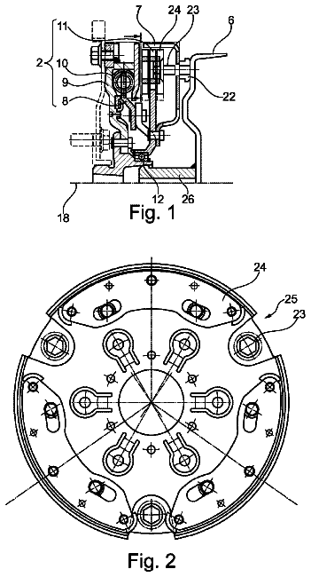
Drawings 2

1 of 2 drawing sheets so far from the published document, cropped to the drawing. Every sheet is in the USPTO PDF.

Figures as described

  • FIG. 1 shows a clutch assembly for a transmission in a motor vehicle drive train in accordance with a first embodiment of the present invention
  • FIG. 2 shows a clutch assembly for a transmission in a motor vehicle drive train in accordance with a second embodiment of the present invention

Claims 18 total, 3 independent

What the patent claimed, word for word. All of it is now free to use.

  1. 1
    Independent claimA clutch assembly for a motor vehicle drive train comprising: a clutch pack; a piston for engaging the clutch pack; a housing including a surface for slidably supporting the piston; a release spring for disengaging the piston from the clutch pack; and a bearing supporting the clutch pack, the bearing including an inner race, a roller element and an outer race, the inner race including a radially extending surface defining an axial stop, the axial stop limiting axial movement of the release spring away from the piston, the release spring including a radially outer portion for forcing the piston away from the clutch pack, the release spring including a radially inner portion extending radially inward from the radially outer portion, the radially inner portion including a radially inner end, the axial stop contacting the radially inner end directly or via a ring to limit the axial movement of the release spring away from the piston, the inner race including an axial protrusion radially inside of the axial stop protruding with respect to the axial stop and configured for axially contacting the housing to align the bearing on the housing.
  2. 2
    The clutch assembly as recited in claim 1 wherein the axial stop contacts the release spring to limit the axial movement of the release spring away from the piston.
  3. 3
    The clutch assembly as recited in claim 1 further comprising the ring sandwiched between the bearing and the housing, the bearing limiting the axial movement of the release spring away from the piston via the ring.
  4. 4
    The clutch assembly as recited in claim 3 wherein the housing includes an axial stop and an axially protruding lip hanging over the axial stop of the housing, the bearing including an axial protrusion received radially inside of the axially protruding lip, the axial protrusion contacting the axial stop of the housing.
  5. 5
    The clutch assembly as recited in claim 4 wherein the ring is sandwiched between the axially protruding lip and a surface of the bearing extending radially away from the axial protrusion.
  6. 6
    The clutch assembly as recited in claim 4 wherein the surface that the piston axially slides along is radially outside of the axially protruding lip.
  7. 7
    The clutch assembly as recited in claim 4 wherein the inner race and the axially protruding lip contact the ring to sandwich the ring.
  8. 8
    The clutch assembly as recited in claim 7 wherein the inner race includes the radially extending surface of the inner race extends radially away from the axial protrusion, the ring being sandwiched between the radially extending surface of the inner race and a radially extending surface of the axially protruding lip.
  9. 9
    The clutch assembly as recited in claim 1 wherein the bearing directly contacts the release spring to hold the release spring against the piston.
  10. 10
    The clutch assembly as recited in claim 9 wherein the inner race directly contacts the release spring.
  11. 11
    The clutch assembly as recited in claim 10 wherein the radially extending surface directly contacts the release spring.
  12. 12
    The clutch assembly as recited in claim 1 wherein the housing includes an axial stop and an axially protruding lip hanging over the axial stop of the housing, the axial protrusion received radially inside of the axially protruding lip, the axial protrusion contacting the axial stop of the housing.
  13. 13
    Independent claimA clutch assembly for a motor vehicle drive train comprising: a clutch pack; a piston for engaging the clutch pack; a housing including a surface for slidably supporting the piston; a release spring for disengaging the piston from the clutch pack; a bearing supporting the clutch pack, the bearing limiting axial movement of the release spring away from the piston; and a ring sandwiched between the bearing and the housing, the bearing limiting the axial movement of the release spring away from the piston via the ring, wherein the housing includes an axial stop and an axially protruding lip hanging over the axial stop, the bearing including an axial protrusion received radially inside of the axially protruding lip, the axial protrusion contacting the axial stop.
  14. 14
    The clutch assembly as recited in claim 13 wherein the ring is sandwiched between the axially protruding lip and a surface of the bearing extending radially away from the axial protrusion.
  15. 15
    The clutch assembly as recited in claim 13 wherein the surface that the piston axially slides along is radially outside of the axially protruding lip.
  16. 16
    Independent claimA clutch assembly for a motor vehicle drive train comprising: a clutch pack; a piston for engaging the clutch pack; a housing including a surface for slidably supporting the piston; a release spring for disengaging the piston from the clutch pack; and a bearing supporting the clutch pack, the bearing limiting axial movement of the release spring away from the piston; wherein the housing includes an axial stop and an axially protruding lip hanging over the axial stop, an inner race of the bearing including an axial protrusion received radially inside of the axially protruding lip, the axial protrusion contacting the axial stop.
  17. 17
    The clutch assembly as recited in claim 16 wherein a radially inner end of the spring is arranged axially between the axially protruding lip and a surface of the bearing extending radially away from the axial protrusion.
  18. 18
    The clutch assembly as recited in claim 16 wherein the surface that the piston axially slides along is radially outside of the axially protruding lip.

Claim map

Independent claims stand on their own. The others add detail to the claim they name.

Claim 111 claims build on it
Claim 132 claims build on it
Claim 162 claims build on it

Description

The present disclosure relates generally to clutch assemblies for motor vehicle transmissions and more particularly to release springs for pistons in clutch assemblies.

Background

U.S. Pat. No. 6,095,941 discloses a clutch assembly including a release spring retained by a snap ring.

Summary of the invention

A clutch assembly for a motor vehicle drive train is provided. The clutch assembly includes a clutch pack; a piston for engaging the clutch pack; a housing including a surface for slidably supporting the piston; a release spring for disengaging the piston from the clutch; and a bearing supporting the clutch pack. The bearing limiting axial movement of the release spring away from the piston.

A method of assembling a clutch assembly for a motor vehicle drive train is also provided. The method includes sliding a piston onto a surface of a housing; sliding a retainer spring against the piston; and sliding an inner race of a bearing onto the housing such that the inner race of the bearing limits axial movement of the release spring away from the piston.

Brief description of the drawings

The present invention is described below by reference to the following drawings, in which:

FIG. 1 shows a clutch assembly for a transmission in a motor vehicle drive train in accordance with a first embodiment of the present invention; and

FIG. 2 shows a clutch assembly for a transmission in a motor vehicle drive train in accordance with a second embodiment of the present invention.

Detailed description

The present disclosure provides a one-way clutch inner race used as a reaction point for a clutch pack release spring. In the embodiments discussed below, the outer race serves as a clutch carrier for a series of clutch plates. The piston is released by a release spring acting between the piston and the inner race.

FIG. 1 shows a clutch assembly 10 for a transmission in a motor vehicle drive train in accordance with a first embodiment of the present invention. Clutch assembly 10 includes a clutch pack 11 formed by a plurality of clutch plates 12 including friction surfaces 14 on both sides thereof that are axially slidable along an outer radial surface of a bearing 18 and a plurality of clutch plates 20 that are axially slidable along an outer support 22 of a housing 24 . An axially slidable piston 26 is forced toward and away from the end clutch plate 20 to engage and disengage clutch pack 11 with an axial extension 27 thereof. In order to engage clutch pack 11 , a force exerted on piston 26 in the direction of clutch pack 11 needs to overcome a force exerted by a return spring 28 onto piston 26 . Return spring 28 is positioned radially inside of axial extension 27 and contacts piston 26 with a radially outer portion 30 thereof. An inner radial end 32 of return spring 28 is held axially in place by a snap ring 34 , which contacts return spring 28 on a side of return spring 28 opposite of a side return spring 28 that contacts piston 26 .

Snap ring 34 includes an inner radially extending portion 36 and an outer radially extending portion 38 that are axially offset from each other by an axially extending portion 40 connecting radially extending portions 36 , 38 . Outer radially extending portion 38 is arranged axially further away from bearing 18 than inner radially extending portion 36 and contacts inner radial end 32 of return spring 28 . In contrast to U.S. Pat. No. 6,095,941, snap ring 34 is not machined into housing 24 . Instead, snap ring 34 is sandwich axially between a radially extending surface 68 of an axially protruding lip 44 of housing 24 and a radially extending surface 66 of inner race 56 that aligns with a radially extending surface 68 . Axially protruding lip 44 hangs over an annularly shaped blind hole 46 formed by an inner radial surface 48 of lip 44 , an axial stop 50 and a first radial support surface 52 of housing 24 . Housing 24 also includes a second radial support surface 54 radially outside of the axially protruding lip 44 , which piston 26 slides axially along during engagement and disengagement of clutch pack 11 .

Bearing 18 is supported by first radial support surface 52 and includes an inner race 56 contacting first radial support surface 52 , a rolling element 58 riding along inner race 56 and an outer race 60 radially outside of rolling bearing 58 that includes a splined surface for receiving clutch plates 12 . Bearing 18 , at inner race 56 , includes an axial protrusion 62 received radially inside of axially protruding lip 44 and contacting axial stop 50 . Protrusion 62 includes an outer radial surface 64 aligned with inner radial surface 48 of lip 44 that extends axially from a radial extending surface 66 of inner race 56 that aligns with a radially extending surface 68 of lip 44 .

To assemble clutch assembly 10 , piston 26 is first slid onto second radial support surface 54 , then retainer spring 28 is slid against piston 26 . Next, snap ring 34 is slid onto housing 24 such that inner radially extending portion 36 contacts a radially extending surface 68 of lip 44 and inner race 56 , either alone or with rolling element 58 and possibly outer race 60 , is slid onto first radial support surface 52 of housing 24 such that protrusion 62 is received radially inside of axially protruding lip 44 and contacts axial stop 50 and radially extending surface 66 of inner race 56 contacts snap ring 34 at inner radially extending portion 36 to fix return spring 28 and snap ring 34 in place.

FIG. 2 shows a clutch assembly 110 for a transmission in a motor vehicle drive train in accordance with a third embodiment of the present invention. Clutch assembly 110 is formed in substantially the same manner as clutch assembly 10 , with the only differences being the constructions of housing 124 , the elimination of snap ring 34 and replacing return spring 28 with a longer return spring 128 . In this embodiment, because snap ring 34 is not used for retaining return spring 128 , housing 124 , like housing 24 from the first embodiment, does not include an annular groove machined therein. Additionally, axially protruding lip 44 is replaced by a more compact axially protruding lip 124 that is spaced away from radially extending surface 66 . Instead of using the housing to help retain return spring 128 , return spring 128 is retained directly by inner race 56 . Inner race 56 is fixed in place on a first support surface 152 of housing such that inner race 56 directly contacts inner radial end 132 of return spring 128 . Radially extending surface 66 of inner race 56 forms an axial stop contacting release spring 128 to limit the axial movement of release spring 128 away from piston 26 .

Axially protruding lip 144 hangs over an annularly shaped blind hole 146 formed by an inner radial surface 148 of lip 144 , an axial stop 150 and first radial support surface 152 of housing 124 . Housing 124 also includes a second radial support surface 154 radially outside of the axially protruding lip 144 , which piston 26 slides axially along during engagement and disengagement of clutch pack 11 .

To assemble clutch assembly 110 , piston 26 is first slid onto second radial support surface 154 , then retainer spring 128 is slid against piston 26 . Next, inner race 56 , either alone or with rolling element 58 and possibly outer race 60 , is slid onto first radial support surface 152 of housing 124 such that an end of protrusion 62 is received radially inside of axially protruding lip 144 and contacts axial stop 150 and radially extending surface 66 of inner race 56 directly contacts inner radial end 132 of return spring 128 to fixed return spring 128 in place.

In comparison with a clutch assembly having an annular groove machined into the housing, clutch assemblies 10 , 110 may be advantageous in that the elimination groove 42 and snap ring 34 saves cost.

In the preceding specification, the invention has been described with reference to specific exemplary embodiments and examples thereof. It will, however, be evident that various modifications and changes may be made thereto without departing from the broader spirit and scope of invention as set forth in the claims that follow. The specification and drawings are accordingly to be regarded in an illustrative manner rather than a restrictive sense.
In this description

About 1,458 words. The USPTO PDF has it with every drawing.

Timeline & family

Timeline From USPTO dates

201420162018202020222024Earliest priority dateNov 1, 2013Application filedOct 28, 2014Application publishedMay 7, 2015Patent grantedNov 21, 20173.5-year fee paidMay 21, 20217.5-year fee not paidMay 21, 2025Patent expiredNov 21, 2025

Maintenance fees

Fees are due 3.5, 7.5 and 11.5 years after grant. This patent expired on November 21, 2025, so the fee marked "not paid" was the one that went unpaid.

3.5-year feeDue May 21, 2021Paid
7.5-year feeDue May 21, 2025Not paid
11.5-year feeDue May 21, 2029Never came due

US family 2 documents, by filing date

Published applicationUS 2015/0122609 A1

CLUTCH PACK RELEASE SPRING ENGAGED WITH INNER RACE

Filed Oct 2014 · published May 2015
Published application
This documentUS 9,822,824 B2

Clutch pack release spring engaged with inner race

Filed Oct 2014 · granted Nov 2017
Lapsed, fee not paid

Earlier publications, parents and continuations. None of them can still be enforced, or this patent would not be listed.

US patents it cites 10

Prior art cited by the examiner or applicant. Useful when you check your own idea for novelty.

Sources & verification

Verification

  • The USPTO Official Gazette of January 20, 2026 lists it as expired on November 21, 2025 for an unpaid maintenance fee.
  • It isn't on any reinstatement notice published since.
  • Its 1 US relative has also lapsed, expired or never issued.
  • Rechecked against USPTO records every day.
  • We check US rights only. Check foreign counterparts before selling abroad.

Confirm it yourself

  1. Open the file history on Patent Center.
  2. The status should read "Patent Expired Due to NonPayment of Maintenance Fees Under 37 CFR 1.362".
  3. Check the documents for any later petition to revive or reinstate.

Everything on this page comes from the documents linked above.

More in Industrial Equipment

All Industrial Equipment
Drawing from US 9,822,808 B2Lapsed, fee not paid4 drawings
Industrial Equipment · US 9,822,808 B2

Penetrated floating nut

A penetrated floating nut includes: a first retaining member including a cylindrical first cylindrical section and a first flange section provided at one end portion of the first cylindrical section; a second retaining…

Filed2016
LapsedNov 2025
OwnerMITSUBISHI AIRCRAFT CORPORATION
Drawing from US 9,822,839 B2Lapsed, fee not paid3 drawings
Industrial Equipment · US 9,822,839 B2

Hydraulically damping rubber bearing

A hydraulically damping rubber bearing has a substantially hollow-cylindrical inner portion and an outer portion disposed with a predetermined spacing relative to the inner portion.

Filed2014
LapsedNov 2025
OwnerBOGE ELASTMETALL GMBH
Drawing from US 9,822,840 B2Lapsed, fee not paid3 drawings
Industrial Equipment · US 9,822,840 B2

Converter unit having a damping system and having a torque transfer unit

A converter unit having a damping system and having a torque transfer unit for connecting an input shaft separably to an output shaft, wherein the torque transfer unit has a co-rotating housing and the damping system…

Filed2013
LapsedNov 2025
OwnerSchaeffler Technologies AG & Co. KG