 Lapsed, fee not paid4 drawings
Industrial Equipment · US 9,822,709 B2
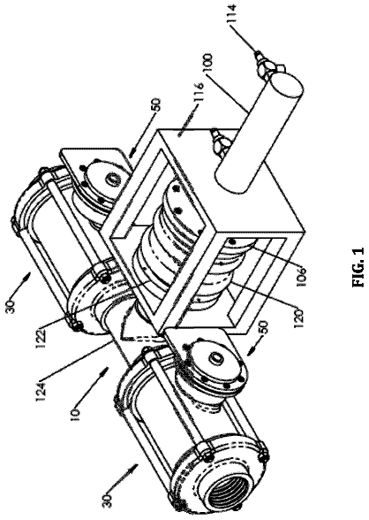
Pneumatic control valve
A control valve for a gas turbine engine air starter.
US 9,822,774 B2 · Assignee: DEBIOTECH S.A. · Inventors: Schneeberger; Niklaus et al.
Sheet 1 of 3 from the published document. All sheets in the USPTO PDF
A micropump in the form of a stack comprising, in succession, a flexible diaphragm, a pumping chamber and a closing-off plate, said pumping chamber communicating with the outside, for example via the flexible diaphragm; said diaphragm being furthermore secured to an actuator arranged outside the micropump, characterized in that said diaphragm is secured to the actuator by way of at least one element in the form of a strip, which is rigid along its main axis and flexible in the direction perpendicular to its main axis.
Such devices are notably described in international patent application WO 2006/056967. These devices generally take the form of a stack, i.e. a support plate, an intermediate layer serving as flexible membrane, a pumping chamber and a closure plate, the pumping chamber communicating with the exterior, for example via the support plate. Part of the membrane is fastened to a piezo-electric element disposed externally of the device. The connection between these two elements is provided by means of at least one element, for example a block produced in the support plate by micromachining.
1 of 3 drawing sheets so far from the published document, cropped to the drawing. Every sheet is in the USPTO PDF.
What the patent claimed, word for word. All of it is now free to use.
This application is the U.S. national phase of International Application No. PCT/IB2010/055310, filed 19 Nov. 2010, which designated the U.S. and claims priority to EP Application No. 09178168.2, filed 7 Dec. 2009, the entire contents of each of which are hereby incorporated by reference.
The invention concerns micropumps obtained by micromachining and adapted to be activated by means of an actuator such as a piezo-electric element.
Such devices are notably described in international patent application WO 2006/056967.
These devices generally take the form of a stack, i.e. a support plate, an intermediate layer serving as flexible membrane, a pumping chamber and a closure plate, the pumping chamber communicating with the exterior, for example via the support plate. Part of the membrane is fastened to a piezo-electric element disposed externally of the device. The connection between these two elements is provided by means of at least one element, for example a block produced in the support plate by micromachining.
The problem that the present invention proposes to solve lies in the difficulty of providing an effective connection between a membrane and an actuator that is deformed when it is activated.
In the case of the invention, the solution to the aforementioned problem consists in a micropump taking the form of a stack successively comprising a support plate, an intermediate layer serving as flexible membrane, a pumping chamber and a closure plate, said pumping chamber communicating with the exterior of the micropump, for example via the support plate, said membrane being fastened to an actuator disposed externally of the micropump, the connection being effected via a passage through the support plate.
The actuator may be chosen from piezo-electric bimorph actuators, piezo-electric multimorph actuators, thermal bimorph actuators and shape memory alloy beams.
Despite its small overall size, this type of actuator can exert high forces, typically of the order of 0.1 N to 100 N.
Moreover, this type of actuator may exert a movement of small amplitude along a non-rectilinear trajectory, for example a circular arc. The length of the trajectory may be less than 1 mm.
The invention is characterized in that said membrane is fastened to the actuator via at least one element taking the form of a strip, rigid along its main axis and flexible in the direction perpendicular to its main axis. The stiffness enables transmission of the force of the actuator into a linear movement of the membrane while the flexibility provides the lateral transmission of that force.
The actuator is preferably a piezo-electric bimorph actuator plate.
The actuator advantageously has a fixed end and a free end, the latter being disposed cantilever-fashion at the exit from the passage. One of the ends of the strip is fixed to said free end.
The strip is preferably stuck to the piezo-electric element.
In a variant of the invention, the strip is in direct contact with the membrane. In this configuration, the strip is preferably stuck to the membrane.
In order to reinforce the sticking, the end of the strip that is fixed to the membrane preferably includes holes or has a crenelated contour.
The strip may be constituted of any material enabling the target objective to be achieved. It is advantageously in stainless steel.
According to one embodiment of the invention, the piezo-electric element includes electrical contacts disposed in the vicinity of said fixed end.
A particularly beneficial configuration consists in fixing the micropump to a rigid part, to which part said fixed end of the piezo-electric element is also fixed. The elements constituting this assembly thus form a closed loop.
During the assembly of these elements, variations of geometry or defects of alignment may nevertheless occur, and do so cumulatively, leading to unacceptable errors or hyperstatism when the last fixing is effected.
In this case the sticking of the membrane of the micropump and the flexible element is preferably effected last. In this way these two elements are fixed in their relative position by the other elements and fixings of the loop.
Fixing (for example gluing) them last thus enables variations of geometry to be absorbed and prevents hyperstatism by fixing this relative position.
The invention is described in more detail hereinafter by means of examples illustrated by the following figures:
FIG. 1 shows a type of micropump that may be used in the context of the present invention.
FIG. 2 represents a variant embodiment of the invention.
FIG. 3 represents one way of fixing the strip to the membrane.
The following numerical references are used in the present application: 1 . Support plate 2 . Flexible membrane 3 . Closure plate 4 . Pumping chamber 5 . Piezo-electric element 6 . Strip 7 . Passage 8 . Fixed end of the piezo-electric element 9 . Free end of the piezo-electric element 10 . Upper end of the strip 11 . Rigid part 12 . Base plate 13 . Transmission block 14 . Lower end of the strip 15 . Electrical contact
The micropump shown in FIG. 1 is formed of elements preferably in silicon and in glass. It is produced by means of micromachining technologies known in themselves. It notably comprises a base plate 12 in glass, a support plate 1 in silicon, a flexible membrane 2 in silicon, a pumping chamber 4 and a closure plate 3 in glass, the pumping chamber 4 being defined between the membrane 2 and the closure plate 3 . A more detailed description of the structure and operation of such a pump is given in U.S. Pat. No. 5,759,014.
A piezo-electric element 5 (not shown in FIG. 1 ) is fastened to a transmission block 13 machined in the support plate 3 .
FIG. 2 is a diagrammatic sectional view of a variant of the invention.
The electrical voltage applied to the fixed end 8 of a piezo-electric element 5 induces its contraction, which contraction is reflected in a circular movement of its free end 9 . The maximum displacement of the piezo-electric element 5 thus occurs at its free end 9 . A plurality of electrical contacts 15 are placed in such a manner that by applying a voltage to each of them movement occurs in either one direction or the other and/or increases the movement.
The free end 9 of the piezo-electric element is attached to an upper end 10 of a strip 6 disposed in a vertical direction, inside a passage 7 of cylindrical shape. The strip 6 , constituted of stainless steel, for example, thus has a horizontal (lateral) flexibility. It may thus move in this direction when a horizontal force acts on it, which in the present instance is produced by means of the piezo-electric element 5 .
It should be noted at this point that prior art systems absorb the horizontal load at pivot points, by integrating parts with rotary movements.
The invention consists mainly in using as the connecting element 6 a strip that is easily deformable horizontally. Moreover, the strip 6 is sufficiently rigid and strong along its main axis to transmit movement of the piezo-electric element to the membrane 2 .
The variant shown in FIG. 2 has the following features: a) A micropump is fixed to a rigid part 11 . b) A fluid is aspirated or discharged as a function of the movement of the strip 6 . c) Electrical contacts 15 are disposed in the vicinity of the fixed point 8 of the piezo-electric element 5 . d) The flexible strip 6 is fixed to the end 9 of the piezo-electric element 5 and to the membrane 2 . When an electrical voltage is applied to one of the contacts of the piezo-electric element 5 , that voltage causes a contraction that is reflected in an angular movement, the greatest movement occurring at the free end 9 of the piezo-electric element 5 . e) The movement induced by the piezo-electric element 5 pulls or pushes the strip 6 along a vertical axis; non-vertical movements are absorbed by deformation of the strip 6 . f) An end 14 of the strip 6 is stuck to the membrane 2 (see FIG. 3 ), the other end 10 being stuck to the piezo-electric element 5 . g) The material of the strip 6 is preferably stainless steel 0.05 mm thick. It is cut and bent to shape. h) To obtain good sticking between the strip 6 and the membrane 2 , cavities (forming crenelations) are cut out from the end concerned of the strip (see FIG. 4 which represents the lower end of the strip 6 in a plane perpendicular to the planes of the other figures). i) The piezo-electric element 5 is preferably a bimorph actuator plate having three electrical contacts. j) The rigid part 11 is subjected to forces transmitted by deformation of the piezo-electric element 5 . To ensure sufficient rigidity for correct operation of the pump, the rigid part 11 is preferably produced in ceramic. k) The membrane 2 is delicate; the connection with the strip 6 is preferably produced by a drop of glue, and a safety distance between the parts prevents damaging the membrane 2 . Variations in thickness of the rigid part or the length of the strip are compensated by more or less deep penetration into the drop of glue. l) The strip 6 is sized and sufficiently rigid to push and pull the membrane 2 , but also sufficiently deformable by buckling within the elastic limit if an overpressure caused by a blockage generates a greater force; this prevents damage to the pump.
It goes without saying that the invention is not limited to the above examples.
About 1,620 words. The USPTO PDF has it with every drawing.
Fees are due 3.5, 7.5 and 11.5 years after grant. This patent expired on November 21, 2025, so the fee marked "not paid" was the one that went unpaid.
FLEXIBLE ELEMENT FOR MICROPUMP
Filed Nov 2010 · published Sep 2012Diaphragm pump having a strip connector
Filed Nov 2010 · granted Nov 2017Earlier publications, parents and continuations. None of them can still be enforced, or this patent would not be listed.
Prior art cited by the examiner or applicant. Useful when you check your own idea for novelty.
Everything on this page comes from the documents linked above.