 Lapsed, fee not paid4 drawings
Consumer Products · US 9,820,522 B2
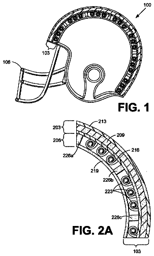
Shock wave mitigating helmets
A helmet, has a shell that includes a first portion and a second portion.
US 9,820,547 B2 · Assignee: CASIO COMPUTER CO., LTD. · Inventors: Yamasaki; Shuichi
Sheet 1 of 11 from the published document. All sheets in the USPTO PDF
A drawing device includes a drawing unit holding a drawing tool for drawing on a drawing target surface in contact with the drawing target surface having a curved shape along a first direction and moving the drawing tool; and a control unit controlling the drawing unit. The control unit controls the drawing unit to perform an operation in which the drawing tool moves on a first and second regions adjacent in the first direction of the drawing target surface along a second direction crossing with the first direction in a state in which the drawing tool is in contact with the drawing target surface, then drawing tool draws on the first and second regions, and an operation in which the drawing tool moves between the first and second regions in a state in which the drawing tool is separated from the drawing target surface.
Conventionally, a nail printer is known which prints a favorite nail design on a finger nail. Such a nail printer is, for example, disclosed in JP 2003-534083 W. By using such a device, a user can easily enjoy nail printing without using a nail salon. Conventionally, a plotter type drawing device is known which includes a pen for drawing and performs drawing by coming into contact with a pen tip on a paper, and such a drawing device is considered to be used as a nail printer. In the case where drawing is performed by a pen, in comparison with an ink jet type printer, an ink having high viscosity and ink including such as a color material having high viscosity and ink including a color material having a large particle diameter can be used for drawing. Therefore, a variation of a nail design which can be drawn is increased by a nail printer. However, in the case where a plotter type drawin
1 of 11 drawing sheets so far from the published document, cropped to the drawing. Every sheet is in the USPTO PDF.
What the patent claimed, word for word. All of it is now free to use.
Corresponding Japanese application
Application Number: Patent Application Number 2015-127624, Date of Application: Jun. 25, 2015 BACKGROUND OF THE INVENTION
The present invention relates to a drawing device and a drawing method for the drawing device.
Conventionally, a nail printer is known which prints a favorite nail design on a finger nail. Such a nail printer is, for example, disclosed in JP 2003-534083 W.
By using such a device, a user can easily enjoy nail printing without using a nail salon.
Conventionally, a plotter type drawing device is known which includes a pen for drawing and performs drawing by coming into contact with a pen tip on a paper, and such a drawing device is considered to be used as a nail printer.
In the case where drawing is performed by a pen, in comparison with an ink jet type printer, an ink having high viscosity and ink including such as a color material having high viscosity and ink including a color material having a large particle diameter can be used for drawing. Therefore, a variation of a nail design which can be drawn is increased by a nail printer.
However, in the case where a plotter type drawing device is used as a nail printer, a drawing target is a nail having a curved shape. Therefore, when a drawing position is changed, a surface with which a pen tip is in contact is changed in a vertical direction (a height direction) depending on the curved shape of a nail.
Herein, in the case where drawing is performed from an end of a nail having a relatively low height to a center of the nail having a relatively high height (specifically, in a case where a pen climbs an inclined surface), a nail may be strongly pushed in a horizontal direction by the pen. When the nail is strongly pushed by the pen as described above, a finger may move accordingly. If a finger moves during drawing, finishing quality of a nail print is lowered.
An advantage of the present invention is to provide a drawing device and a drawing method for the drawing device, and the drawing device can perform highly fine drawing by reducing that a nail is pushed in a width direction of the nail by a drawing tool during drawing and accordingly reducing that a finger is moved by being pushed by the drawing tool during drawing.
According to an embodiment of the present invention, there is provided a drawing unit which holds a drawing tool for drawing on a drawing target surface in contact with the drawing target surface and moves the drawing tool; and a control unit which controls the drawing unit, wherein the drawing target surface has a curved shape along a first direction, the drawing unit sets the drawing tool either a first state in which the drawing tool is in contact with the drawing target surface and a second state in which the drawing tool is separated from the drawing target surface, the control unit controls the drawing unit so that the drawing tool moves along a second direction crossing with the first direction on a first region and a second region of the drawing target surface in the first state as a first operation, therefore the drawing tool draws on the first region and the second region, the first region and the second region are separated each other along the first direction, and controls the drawing unit so that the drawing tool moves between the first region and the second region in the second state as a second operation.
According to another embodiment of the present invention, there is provided a drawing method for a drawing device, the drawing device including a drawing unit which holds a drawing tool for drawing on a drawing target surface in contact with the drawing target surface and moves the drawing tool, the drawing target surface has a curved shape along a first direction, the drawing unit sets the drawing tool either a first state in which the drawing tool is in contact with the drawing target surface and a second state in which the drawing tool is separated from the drawing target surface, the drawing method comprising: a first operation step in which the drawing tool moves along a second direction crossing with the first direction on a first region and a second region of the drawing target surface in the first state by the drawing unit, therefore the drawing tool draws on the first region and the second region, and the first region and the second region are separated each other along the first direction; and a second operation step in which the drawing tool moves between the first region and the second region in the second state by the drawing unit.
FIG. 1A is an elevation view of a drawing device according to embodiments described herein;
FIG. 1B is a side view of an internal configuration of the drawing device illustrated in FIG. 1A ;
FIG. 2 is a II-II sectional view in FIG. 1 ;
FIG. 3A is a top view of a drawing head according to the embodiments;
FIG. 3B is a side view of the drawing head according to the embodiments;
FIG. 4 is a block diagram of a main portion indicating a control configuration of the drawing device according to the embodiments;
FIG. 5A is a view illustrating an image of nail design image data;
FIG. 5B is an image view illustrating a state in which the nail design illustrated in FIG. 5A is fit to a nail;
FIGS. 6A and 6B are views for describing a procedure for drawing processes according to a first embodiment;
FIG. 7 is a flowchart indicating the drawing processes according to the first embodiment;
FIG. 8 is a view for describing a procedure for drawing processes according to a second embodiment;
FIG. 9 is a flowchart illustrating the drawing processes according to the second embodiment;
FIG. 10 is a view for describing a procedure for drawing processes according to a third embodiment; and
FIGS. 11A to 11E are views for describing examples of curving patterns on a nail according to the third embodiment.
Embodiments of a nail printer (drawing device) and a drawing method for the nail printer (drawing device) according to the present invention will be described in detail below with reference to the drawings.
In each embodiment to be described below, technically preferable various limitations are applied to implement the present invention. However a scope of the present invention is not limited to each embodiment to be described below and illustrated examples.
In each embodiment to be described below, it is described that a nail printer performs drawing on a surface of a finger nail as a drawing target surface. However, the drawing target surface in the present invention is not limited to the surface of a finger nail, and, for example, the drawing target surface may be a surface of a toe nail. First Embodiment
FIG. 1A is an elevation view of a nail printer and indicates an internal configuration of the nail printer.
FIG. 1B is a side view indicating an internal configuration of the nail printer illustrated in FIG. 1A .
FIG. 2 is a sectional view along line II-II in FIG. 1A .
As illustrated in FIGS. 1A and 1B , a nail printer 1 according to a first embodiment is a drawing device in which a drawing head 43 includes a pen 41 which is a drawing tool and an ink jet drawing unit 71 , and drawing is performed on a nail T of a print finger U 1 by using both of a plotter method and an ink jet method.
This nail printer 1 includes a case body 2 and a device body 10 stored in the case body 2 .
A lid 23 which can be opened and closed to exchange the pen 41 and the ink jet drawing unit 71 of a drawing unit 40 to be described later is provided to one end of an upper side surface of the case body 2 .
The lid 23 is rotatable from a close state to an open state as illustrated in FIG. 1A , for example, via a hinge.
An operation unit 25 (refer to FIG. 4 ) is displaced on an upper surface (top plate) of the case body 2 .
The operation unit 25 is an input unit, and a user performs various input by using the input unit.
The operation unit 25 includes operation buttons (not illustrated) for performing various input, including a power switch button for turning on the nail printer 1 , a stop switch button for stopping an operation, a design selection button for selecting a design image to be drawn on the nail T, and a drawing start button for starting drawing.
A display unit 26 is provided at an almost center portion on an upper surface (top plate) of the case body 2 .
The display unit 26 includes, for example, a liquid crystal display (LCD), an organic electroluminescence display, and other flat display.
In the embodiment, this display unit 26 appropriately displays, for example, a nail image obtained by imaging the print finger U 1 (a finger image including an image of the nail T), an image of such as an outline of the nail T included in the nail image, a design selection screen for selecting a design image to be drawn on the nail T, a thumbnail image for design confirmation, and an instruction screen for displaying various instructions.
A touch panel for performing various input may be integrally formed on a front face of the display unit 26 .
The device body 10 is formed substantially in a box shape and includes a lower machine frame 11 and an upper machine frame 12 . The lower machine frame 11 is disposed on an inner lower side of the case body 2 . The upper machine frame 12 is disposed on an upper side of the lower machine frame 11 and on an inner upper side of the case body 2 .
First, the lower machine frame 11 will be displayed.
The lower machine frame 11 includes a back plate 111 , a bottom plate 112 , a pair of right/left side plates 113 a and 113 b , an X direction moving stage storage unit 114 , a Y direction moving stage storage unit 115 , and a partition wall 116 .
Lower ends of the side plates 113 a and 113 b are connected to each of right and left ends of the bottom plate 112 , and the side plates 113 a and 113 b are erected on the bottom plate 112 .
A lower portion of the back plate 111 is formed so as to be recessed in two steps toward a front side (front side in a finger insertion direction).
A lower end of the back plate 111 is connected to a front end of the bottom plate 112 , and the back plate 111 partitions a region surrounded by the bottom plate 112 and the side plates 113 a and 113 b into front and rear sides.
A space formed on a back side of the recessed back plate 111 becomes the X direction moving stage storage unit 114 and the Y direction moving stage storage unit 115 (refer to FIG. 1B ).
When the drawing unit 40 moves forward (a front side in a finger insertion direction), an X direction moving stage 45 of the drawing unit 40 is stored in the X direction moving stage storage unit 114 .
A Y direction moving stage 47 of the drawing unit 40 is displayed in the Y direction moving stage storage unit 115 .
The partition wall 116 is provided on an inner side of the lower machine frame 11 so as to partition a space on an inner front side of the lower machine frame 11 into an upper and lower sides (a space in a front side of a finger insertion direction surrounded by the back plate 111 , the bottom plate 112 , the side plates 113 a and 113 b .)
The partition wall 116 is provided substantially horizontally, right/left ends of the partition wall 116 are respectively connected to the side plates 113 a and 113 b , and a rear end of the partition wall 116 is connected to the back plate 111 .
A finger fixing unit 30 (refer to FIG. 1B ) is integrally provided to the lower machine frame 11 .
The finger fixing unit 30 includes a finger reception unit 31 and a finger evacuation unit 32 . The finger reception unit 31 receives a finger corresponding to the nail T to be drawn (hereinafter called “a print finger U 1 ”). Fingers other than the print finger U 1 (hereinafter called “non-print fingers U 2 ”) are evacuated in the finger evacuation unit 32 .
The finger reception unit 31 is disposed on an upper side of the partition wall 116 and at a substantially center in a width direction of the lower machine frame 11 .
A space partitioned into a lower side of the lower machine frame 11 by the partition wall 116 forms the finger evacuation unit 32 .
For example, in the case where drawing is performed on the nail T of a third finger, the third finger is inserted into the finger reception unit 31 as the print finger U 1 , and other four fingers which are the non-print fingers U 2 (the thumb, the forefinger, the middle finger, and the little finger) are inserted into the finger evacuation unit 32 .
As illustrated in FIGS. 1B and 2 , the finger reception unit 31 is opened on a front surface side of the lower machine frame 11 (a front side in a print finger insertion direction). A lower side, both sides, and a deep side are respectively partitioned by a finger placement unit 116 a including a part of the partition wall 116 , partitions 31 a and 31 b , and a partition 31 c.
The finger placement unit 116 a is a unit in which the nail T to be drawn (print finger U 1 ) is placed on an XY plane.
An upper side of the finger reception unit 31 is partitioned by a ceiling 31 d.
A window 31 e for exposing the nail T of the print finger U 1 inserted into the finger reception unit 31 is formed on the ceiling 31 d.
A front wall 31 f (refer to FIG. 1A ) which closes a front surface side of the lower machine frame 11 is erected on both sides on a front surface side of the lower machine frame 11 which is on an upper surface of the partition wall 116 .
A pair of guide walls 31 g (refer to FIG. 1A ) is erected on the upper surface of the partition wall 116 . The guide walls 31 g are narrowed from an end on a center side of the front wall 31 f toward the finger reception unit 31 and guide the print finger U 1 in the finger reception unit 31 .
A user can sandwich the partition wall 116 between the print finger U 1 inserted into the finger reception unit 31 and the non-print fingers U 2 inserted into the finger evacuation unit 32 . Therefore, the print finger U 1 inserted into the finger reception unit 31 is stably fixed.
On an upper surface of the lower machine frame 11 which is on a side of the finger reception unit 31 (a right side in FIGS. 1A and 2 according to the embodiment), a home area 60 , in which the drawing head 43 to be described later waits while drawing is not performed, is provided in a movable range of the drawing head 43 .
A pen cap 62 is disposed in the home area 60 . The quantity of the pen cap 62 corresponds to the quantity of a pen holder 42 to be described later (one in the embodiment).
The pen cap 62 is formed of such as rubber. When drawing is not performed in a state in which the pen 41 is attached to the drawing unit 40 (during non drawing), the pen 41 is moved down, and a pen tip 413 is stored in the pen cap 62 to prevent dry of the pen tip 413 .
An ink jet maintenance unit 63 is provided in the home area 60 and at a position corresponding to a position in which the ink jet drawing unit 71 is disposed when the pen tip 413 is stored in the pen cap 62 .
The ink jet maintenance unit 63 includes such as a cleaning mechanism (not illustrated) for cleaning an ink ejection unit (a nozzle surface) of the ink jet drawing unit 71 to be described later and a cap mechanism (not illustrated) for keeping a moisturized state of the ink ejection unit (a nozzle surface).
An arrangement of the pen cap 62 and the ink jet maintenance unit 63 in the home area is not limited to the example described herein.
The drawing unit 40 includes such as the drawing head 43 , a unit supporting member 44 supporting the drawing head 43 , an X direction moving stage 45 to move the drawing head 43 in an X direction (X direction in FIGS. 1A and 2 and right and left directions of the drawing device 1 ), an X direction moving motor 46 , a Y direction moving stage 47 to move the drawing head 43 in a Y direction (Y direction in FIGS. 1B and 2 and front and rear directions of the drawing device 1 ), and a Y direction moving motor 48 .
FIG. 3A is a top view of the drawing head 43 according to the embodiment. FIG. 3B is a side view of the drawing head 43 .
As illustrated in FIGS. 3A and 3B , the pen holder 42 for holding the pen 41 and an ink jet holder 72 for holding the ink jet drawing unit 71 are arranged adjacent each other to the drawing head 43 according to the embodiment.
The ink jet drawing unit 71 is an ink cartridge-integrated head in which ink cartridges (not illustrated) and an ink ejection unit (not illustrated) are integrally formed. The ink cartridges correspond to inks of, for example, yellow (Y: YELLOW), magenta (M: MAGENTA), and cyan (C: CYAN). The ink ejection unit is provided on a surface (a lower surface in such as FIG. 1A in the embodiment) opposing to a drawing target (the nail T) in each ink cartridge.
The ink ejection unit includes a nozzle array having multiple nozzles to jet ink of each color. The ink jet drawing unit 71 performs drawing by forming ink into fine droplets and directly spraying the ink on a surface to be drawn of a drawing target (the nail T) from the ink ejection unit.
The ink jet drawing unit 71 is not limited to a unit for ejecting ink of the above three colors. An ink cartridge for storing other inks and an ink ejection unit may be further included.
One pen 41 can be attached to the pen holder 42 according to the embodiment.
The pen 41 is a writing tool and performs drawing by which a tip comes into contact with a surface of the nail T which is a drawing target surface.
As illustrated in such as FIG. 3B , in the pen 41 , a pen tip 413 is provided on a tip side of a stick-shaped pen shaft 411 (a lower side in FIG. 3B ). The inside of the pen shaft 411 is an ink storage unit for storing each type of ink.
As ink stored in the pen shaft 411 , each type of ink can be applied. Viscosity of ink and a particle diameter (particle size) of a color material are not limited. For example, a gold and silver lame-containing ink, a write ink, a UV-curable ink, a gel nail, an ink for undercoating, an ink for topcoating, and a manicure liquid can be used.
In the embodiment, the pen 41 , for example, draws in a way in which the ink stored in the pen shaft 411 oozes out when the pen tip 413 is pressed on a surface of the nail T and has a ball-point pen-type pen tip 413 .
The pen 41 is not limited to the ball-point pen-type. For example, the pen 41 may be a felt-tip pen-type pen which draws in a way in which a felt-like pen tip is soaked with ink and a brush pen-type pen which draws in a way in which a brush is soaked with ink. The pen tips 413 having various widths can be prepared.
The pens 41 held by the pen holder 42 may be pens having same-type pen tips 413 or having different-type pen tips 413 .
The pen 41 is held by inserting into the pen holder 42 from upward. Therefore, the pen 41 can be easily exchanged by opening the lid 23 provided to the case body 2 and picking and drawing an upper end of the pen shaft 411 by hand or by tweezers.
Accordingly, a user can realizes a wide range of nail designs by appropriately exchanging the pen 41 attached to the pen holder 42 to the pen 41 of a different color, the pen 41 having a different-type pen tip 413 , or the pen 41 using a different-type ink, depending on a nail design to be drawn.
In the embodiment, when the pen 41 is attached to the pen holder 42 , a user inputs from such as the operation unit 25 what type of the pen 41 is attached to the pen holder 42 and registers the information.
Specifically, for example, an identification number to identify a shape and a width of the pen tip 413 of the pen 41 and the type of stored ink is applied to each of the pens 41 , and a user inputs the identification number from such as the operation unit 25 .
By applying such as a bar code indicating the identification number to the pen 41 and providing such as a bar code reader to read the bar code on the pen holder 42 side, when the pen 41 is set to the pen holder 42 , the identification number may be automatically read and information of the pen 41 may be registered.
The registered information on the pen 41 is stored in a pen information storage region 824 in the storage unit 82 .
The pen holder 42 includes a cylindrical member 421 , a pen locking member 422 , and an auxiliary shaft member 423 . The cylindrical member 421 vertically opens, and the pen 41 is inserted into the cylindrical member 421 . The pen locking member 422 is disposed so as to close an opening on a lower side of the cylindrical member 421 (a lower side in FIG. 3B ). The auxiliary shaft member 423 vertically moves with the pen 41 .
A locking hole 422 a to lock a tip side of the pen shaft 411 of the pen 41 is formed to the pen locking member 422 .
The pen 41 is locked in the pen holder 42 by which the tip side of the pen shaft 411 is fitted into the locking hole 422 a of the pen locking member 422 .
A screw groove (not illustrated) is formed on an outer peripheral surface on a tip side of the pen shaft 411 , a screw groove (not illustrated) which can be screwed with the screw groove of the shaft is provided on an inner peripheral surface of the locking hole 422 a , and the pen 41 may be locked by the locking hole 422 a by which the screw groove on the shaft 411 side is screwed with the screw groove on the locking hole 422 a side.
According to the embodiment, two auxiliary shaft members 423 are disposed so as to sandwich the pen 41 . A lower end of each auxiliary shaft member 423 is fitted into the pen locking member 422 . Accordingly, the auxiliary shaft member 423 is fixed in parallel with the pen shaft 411 of the pen 41 .
The locking projection 424 projecting in a direction away from a shaft center of the pen 41 is provided to the auxiliary shaft member 423 .
A coil spring 425 is wound around a shaft of the auxiliary shaft member 423 .
The coil spring 425 energizes the auxiliary shaft member 423 in an upper direction D 1 in a state in which an external force is not applied, and while drawing is not performed, the pen 41 is held at a position where the pen tip 413 does not come into contact with the nail T.
A motor 426 for vertically moving a pen, a gear 428 , and a plate spring 429 are provided near the pen holder 42 . The motor 426 for vertically moving a pen includes a stepping motor. The gear 428 meshes with a gear wheel 427 attached to a rotation shaft of the motor 426 for vertically moving a pen. The plate spring 429 rotates following rotation of the gear 428 .
In the embodiment, such as the motor 426 for vertically moving a pen, the gear wheel 427 , the gear 428 , and the plate spring 429 form a lifting mechanism of the pen 41 .
Herein, the plate spring 429 is engaged with the locking projection 424 provided to the auxiliary shaft member 423 , and the pen 41 can be pushed down in a lower direction D 2 by pushing down the locking projection 424 .
Specifically, the plate spring 429 rotates with rotation of the motor 426 for vertically moving a pen, and the plate spring 429 is engaged with the locking projection 424 . When the locking projection 424 is pushed down, the pen 41 is pushed down in the lower direction D 2 against an energizing force of the coil spring 425 .
As described above, in the embodiment, the pen 41 is not directly pushed down by the plate spring 429 , and the locking projection 424 is pushed down. Since the plate spring 429 does not cover an upper side of the pen 41 , the pen 41 can be easily exchanged. Further, the height of a lifting mechanism of the pen 41 can be relatively reduced, and therefore a space can be saved.
Herein, operation of a lifting mechanism of the pen 41 will be specifically described.
First, while drawing is not performed, the plate spring 429 does not apply an external force to the locking projection 424 .
In a state in which an external force (a pushing force by the plate spring 429 ) is not applied as described above, the pen 41 is pushed up by an energizing force of the coil spring 425 in the upper direction D 1 (an upper direction in FIGS. 1A and 3B ), and the pen tip 413 which is a tip of the pen 41 is separated from a surface of the nail T which is a drawing target surface and held at a height in which the pen tip 413 does not come into contact with the surface.
On the other hand, during drawing, the motor 426 for vertically moving a pen is rotated by the predetermined number of steps and pushes down the locking projection 424 by the plate spring 429 . Accordingly, the pen 41 is pushed down in the lower direction D 2 .
In the case where the motor 426 for vertically moving a pen is driven, the predetermined number of steps is appropriately set in accordance with such as the height H of the nail T of the print finger U 1 inserted into the finger reception unit 31 .
Specifically, in the nail printer 1 according to the embodiment, nail information to be described later is obtained in advance. Then, based on the nail information, the height H of the nail T coming into contact with the pen tip 413 which is a tip of the pen 41 is recognized, and the number of steps of the motor 426 for vertically moving a pen is determined according to the height H. The motor 426 for vertically moving a pen is driven by the number of steps determined in this manner, and the pen 41 is pushed down by the plate spring 429 . Accordingly, the pen tip 413 of the pen 41 is approached and contacted to a surface of the nail T and applies a proper pen pressure on the nail T.
When the height H in which drawing is performed on the nail T is changed with a change in a position to be drawn while drawing, a pen pressure of the pen 41 is adjusted each time by increasing and decreasing the number of steps of the motor 426 for vertically moving a pen, and drawing is performed while adjusting the pen pressure so as to be substantially stable.
Adjustment of the pen pressure by increasing and decreasing the number of steps of the motor 426 for vertically moving a pen is performed every time when the height H of the nail T is changed by a predetermine amount (for example 0.5 mm), and the pen pressure is not adjusted when the height H of the nail T is changed less than the predetermined amount. However, at this time, the plate spring 429 is bent and deformed (elastic deformation) according to a shape of the nail T, and accordingly the pen 41 automatically moves up and down. Therefore, the pen 41 can certainly come into contact with the nail T, and a pen pressure can be reasonably secured.
A spring constant of the plate spring 429 is not so large, and this spring constant is set to a value such that the nail T does not feel pain when a pushing force (external force) by the plate spring 429 is applied to the nail T.
While drawing, by moderately bending the plate spring 429 , a shock by vertical movement of the pen 41 is absorbed. Further, the pen 41 vertically moves following a change in the height H of the nail T while keeping a state in which a substantially stable moderate pen pressure is applied to the pen tip 413 , and a desired nail design can be finely drawn on a surface of the nail T which is a drawing target.
A unit supporting member 44 is fixed to an X direction moving unit 451 attached to the X direction moving stage 45 . The X direction moving unit 451 moves in an X direction along a guide (not illustrated) on the X direction moving stage 45 by driving the X direction moving motor 46 . Thus, the drawing head 43 attached to the unit supporting member 44 moves in the X direction (an X direction in FIG. 1A , and right and left directions of the nail printer 1 ).
The X direction moving stage 45 is fixed to a Y direction moving unit 471 on a Y direction moving stage 47 . The Y direction moving unit 471 moves in a Y direction along a guide (not illustrated) on the Y direction moving stage 47 by driving the Y direction moving motor 48 . Thus, the drawing head 43 attached to the unit supporting member 44 moves in the Y direction (the Y direction in FIG. 1B , and front and rear directions of the nail printer 1 ).
In the embodiment, the X direction moving stage 45 and the Y direction moving stage 47 are formed by combining the X direction moving motor 46 and the Y direction moving motor 48 with a ball screw (not illustrated) and a guide (not illustrated).
In the embodiment, a head moving unit 49 is formed by the X direction moving motor 46 and the Y direction moving motor 48 as an XY driving unit which drives the drawing head 43 including the pen 41 in an X direction and a Y direction.
The motor 426 for vertically moving a pen, the ink jet drawing unit 71 , the X direction moving motor 46 , and the Y direction moving motor 48 in the drawing unit 40 are connected to a drawing control unit 815 (refer to FIG. 4 ) in a control device 80 to be described later and controlled by the drawing control unit 815 .
An imaging unit 50 includes an imaging device 51 and a lighting device 52 .
The imaging unit 50 illuminates the nail T of the print finger U 1 which is inserted in the finger reception unit 31 and can be seen from the window 31 e by the lighting device 52 . The imaging device 51 images the print finger U 1 , and a nail image which is an image of the nail T of the print finger U 1 (a finger image including a nail image) is obtained.
In the embodiment, the imaging device 51 and the lighting device 52 are fixed on a side (a left side of the drawing head 43 in FIG. 1A ) of the drawing head 43 of the drawing unit 40 .
Specifically, as illustrated in FIG. 3A , the drawing head 43 of the drawing unit 40 includes an overhanding portion 401 which overhangs on one end side (left side in FIG. 3A ) of an upper surface, and a substrate 53 is attached to this overhanding portion 401 .
The imaging device 51 and the lighting device 52 included in the imaging unit 50 are provided so as to oppose to the partition wall 116 on a lower surface of the substrate 53 .
A size of the substrate 53 and positions of the imaging device 51 and the lighting device 52 attached to the substrate 53 are not limited.
The imaging device 51 is a compact camera including, for example, a solid state imaging device having more than two million pixels and a lens.
To detect such as a curvature of the nail T of the print finger U 1 , the imaging device 51 images the nail T from at least two different positions and angles by movement of the head moving unit 49 . Accordingly, at least two nail images are obtained, and based on these nail images, a nail information detection unit 812 to be described later detects nail information on such as an outline of the nail T (a shape of the nail T) a curved shape of the nail T (a curvature of the nail T), and a vertical position of the nail T.
In the embodiment, the imaging device 51 can image in which the imaging device 51 is moved by the head moving unit 49 to an upper side of the nail T of the print finger U 1 inserted into the finger reception unit 31 . Therefore, an imaging possible range of the imaging device 51 covers at least one nail T.
The lighting device 52 is a lighting lamp of such as while LED.
In the embodiment, two lighting devices 52 are arranged so as to sandwich the imaging device 51 on a front side and a deep side of the imaging device 51 . The lighting devices 52 illuminates an imaging range on a lower side of the imaging device 51 by emitting a light downward.
The number and arrangement of the provided lighting devices 52 are not limited to the illustrated example.
The imaging unit 50 is connected to an imaging control unit 811 (refer to FIG. 4 ) in the control device 80 to be described later and controlled by the imaging control unit 811 .
Image data of an image imaged by the imaging unit 50 is stored in a nail image storage region 821 in the storage unit 82 to be described later.
The control device 80 is, for example, arranged on such as the substrate 13 disposed on the upper machine frame 12 .
FIG. 4 is a block diagram of a main portion indicating a control configuration according to the embodiments.
The control device 80 is a computer including the control unit 81 and the storage unit 82 as illustrated in FIG. 4 . The control unit 81 includes a central processing unit (CPU) (not illustrated). The storage unit 82 includes read only memory (ROM) (not illustrated) and random access memory (RAM) (not illustrated).
The storage unit 82 stores various-type programs and data to operate the nail printer 1 .
Specifically, the ROM in the storage unit 82 stores various programs including a nail information detection program, a drawing data generation program, and a drawing program. The nail information detection program is a program for detecting nail information on such as a shape and an outline of the nail T from a nail image. The drawing data generation program is a program for generating drawing data. The drawing program is a program for performing a drawing process. Each unit in the nail printer 1 is totally controlled by which these programs are executed by the control device 80 .
In the embodiment, the storage unit 82 includes the nail image storage region 821 , a nail information storage region 822 , a nail design storage region 823 , and a pen information storage region 824 . The nail image storage region 821 stores a nail image of the nail T of the print finger U 1 of a user, which is obtained by the imaging unit 50 . The nail information storage region 822 stores nail information (an outline and an inclination angle of the nail T) detected by the nail information detection unit 812 . The nail design storage region 823 stores image data of a nail design to be drawn on the nail T. The pen information storage region 824 stores information on the pen 41 .
In a functional view, the control unit 81 includes an imaging control unit 811 , the nail information detection unit 812 , the drawing data generation unit 813 , a display control unit 814 , and the drawing control unit 815 .
Functions as the imaging control unit 811 , the nail information detection unit 812 , the drawing data generation unit 813 , the display control unit 814 , and the drawing control unit 815 are realized by which programs stored in a CPU in the control unit 81 and ROM in the storage unit 82 are executed together.
The imaging control unit 811 controls the imaging device 51 and the lighting device 52 of the imaging unit 50 and causes the imaging device 51 to image a finger image including an image of the nail T of the print finger U 1 inserted into the finger reception unit 31 (hereinafter called “a nail image”).
In the embodiment, the imaging device 51 is moved by the drawing control unit 815 which controls the head moving unit 49 , and the imaging control unit 811 causes the imaging device 51 to obtain at least two nail images from two different positions and angles (for example, from immediately above the nail T and from diagonally upward of the nail T).
An image data of a nail image obtained by the imaging unit 50 is stored in the nail image storage region 821 in the storage unit 82 .
The nail information detection unit 812 is for detecting nail information on the nail T of the print finger U 1 based on an image of the nail T of the print finger U 1 inserted into the finger reception unit 31 , which is imaged by the imaging device 51 .
Herein, nail information means, for example, an outline of the nail T (such as a nail shape, an XY coordinate at a horizontal position of the nail T), the height H of the nail T (position in a vertical direction of the nail T, hereinafter called “a vertical position of the nail T” or simply “a position of the nail T”), and an inclination angle with respect to an XY plane on a surface of the nail T (an inclination angle of the nail T, and a nail curvature).
The length of a width direction W (a horizontal direction, a first direction) and an extending direction L (a longitudinal direction, a second direction) of the nail T are obtained from an XY coordinate at a horizontal position of the nail T.
The nail information detection unit 812 can accurately detect a curvature of the nail T by detecting nail information by using a plurality of nail images imaged from different positions and angles (for example, from immediately above the nail T and from diagonally upward of the nail T).
The drawing data generation unit 813 generates data for drawing performed on the nail T of the print finger U 1 by the drawing head 43 based on a nail information detected by the nail information detection unit 812 .
FIG. 5A is an image view of nail design image data D.
FIG. 5B is an image view illustrating a state in which the nail design illustrated in FIG. 5A is fitted into the nail T.
For example, in the case where, as illustrated in FIG. 5A , the nail design image data D includes a painted-out drawing region Da at a portion corresponding to a tip side of the nail T and a flower-shaped painted-out drawing region Db at a portion corresponding to a substantially center of the nail T, the drawing data generation unit 813 performs a fitting process by expanding, reducing, and cutting out the nail design image data D based on a shape of the nail T detected by the nail information detection unit 812 , and generates drawing data for performing drawing on the nail T as illustrated in FIG. 5B .
The drawing data generation unit 813 fits the nail design image data into a shape of the nail T according to the nail information detected by the nail information detection unit 812 , and a curved surface is suitably corrected.
Accordingly, the nail design drawing data drawn by the pen 41 and the ink jet drawing unit 71 is generated.
The display control unit 814 controls the display unit 26 and causes the display unit 26 to display various display images.
In the embodiment, the display control unit 814 causes the display unit 26 to display, for example, a nail design selection screen, a thumbnail image for design confirmation, a nail image obtained by imaging the print finger U 1 , each instruction screen, and an operation screen.
The drawing control unit 815 is a control unit which outputs a control signal to the drawing unit 40 based on drawing data generated by the drawing data generation unit 813 and controls such as the X direction moving motor 46 , the Y direction moving motor 48 , the motor 426 for vertically moving a pen, and the ink jet drawing unit 71 of the drawing unit 40 so as to perform drawing to the nail T according to the drawing data.
Specifically, the drawing control unit 815 controls the motor 426 for vertically moving a pen while the pen 41 is not drawing and keeps a state in which the locking projection 424 is not pushed down by the plate spring 429 .
During drawing, the drawing control unit 815 operates the motor 426 for vertically moving a pen and controls operation of the motor 426 for vertically moving a pen such that the locking projection 424 is pushed down by the plate spring 429 , and a tip end of the pen 41 (the pen tip 413 ) comes into contact with a surface of the nail T.
At a portion which cannot be fitted even if the plate spring 429 bends and deforms (elastic deformation) since the height H of the nail T significantly changes, the drawing control unit 815 preferably appropriately increases and decreases the number of steps of the motor 426 for vertically moving a pen, adjust a pen pressure of the pen 41 with respect to the nail T, and substantially stabilizes the pen pressure.
In the embodiment, when the pen 41 performs drawing, the drawing control unit 815 causes the pen 41 to draw each line along an extending direction of the nail T.
FIGS. 6A and 6B are views for describing a procedure for a drawing process by the pen 41 according to the embodiment.
In FIG. 6A , an upper view is a view illustrating a sectional shape of the nail T in the width direction W, and a lower view is a plan view viewing the nail T from upward.
FIG. 6B is an enlarged view of regions AR 1 and AR 2 in the lower view of FIG. 6A .
The description continues in the full USPTO document.
About 7,626 words. The USPTO PDF has it with every drawing.
Fees are due 3.5, 7.5 and 11.5 years after grant. This patent expired on November 21, 2025, so the fee marked "not paid" was the one that went unpaid.
DRAWING DEVICE AND DRAWING METHOD OF THE SAME
Filed Apr 2016 · published Dec 2016Drawing device and drawing method of the same
Filed Apr 2016 · granted Nov 2017Earlier publications, parents and continuations. None of them can still be enforced, or this patent would not be listed.
Prior art cited by the examiner or applicant. Useful when you check your own idea for novelty.
Everything on this page comes from the documents linked above.


