Lapsed, fee not paid7 drawings
Industrial Equipment · US 9,819,163 B1
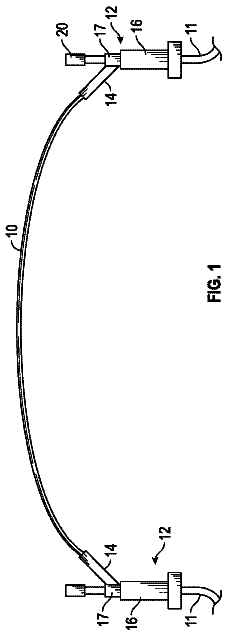
Flexible cable tray section
A flexible cable tray adapted to connect to cable tray sections.
US 9,819,881 B2 · Assignee: PANASONIC INTELLECTUAL PROPERTY MANAGEMENT CO., LTD. · Inventors: Terashima; Yuuji et al.
Sheet 1 of 19 from the published document. All sheets in the USPTO PDF
A detection camera includes an imaging optical unit and a light receiving unit that acquire image data, a first detection processing unit that detects a specified substance, a second detection processing unit that acquires distance information from the imaging optical unit to the specified substance, and a display control unit that outputs display data in which information regarding the specified substance is combined with the image data in a case where the distance information is in a detection target distance range.
In the related art, as a method of detecting whether or not water is contained in an object, there is a method in which infrared light with a wavelength band which is absorbed by water and infrared light with a wavelength band in which absorption of the water slightly changes are sequentially applied to an object to be detected, and the detection is performed on the basis of the intensity of each beam of infrared light reflected from the object to be detected. For example, in a water content detection device disclosed in FIG. 2 of Japanese Patent No. 3466360, an object to be detected is sequentially irradiated with light which has a peak of spectral sensitivity on a side (for example, 1.3 μm) shorter than an absorptive wavelength band of water, light which has a peak of spectral sensitivity in the absorptive wavelength band (for example, 1.45 μm) of the water, and light which has a peak
1 of 19 drawing sheets so far from the published document, cropped to the drawing. Every sheet is in the USPTO PDF.
What the patent claimed, word for word. All of it is now free to use.
The present invention relates to an image output apparatus, an image output method, and an image output system, for outputting image data.
In the related art, as a method of detecting whether or not water is contained in an object, there is a method in which infrared light with a wavelength band which is absorbed by water and infrared light with a wavelength band in which absorption of the water slightly changes are sequentially applied to an object to be detected, and the detection is performed on the basis of the intensity of each beam of infrared light reflected from the object to be detected.
For example, in a water content detection device disclosed in FIG. 2 of Japanese Patent No. 3466360, an object to be detected is sequentially irradiated with light which has a peak of spectral sensitivity on a side (for example, 1.3 μm) shorter than an absorptive wavelength band of water, light which has a peak of spectral sensitivity in the absorptive wavelength band (for example, 1.45 μm) of the water, and light which has a peak of spectral sensitivity on a side (for example, 1.55 μm) longer than the absorptive wavelength band of the water. The water content detection device determines the water content of the object to be detected on the basis of each beam of light reflected from the object to be detected during irradiation with light with a wavelength of 1.3 μm, during irradiation with both light with a wavelength of 1.3 μm and light with a wavelength of 1.45 μm, during irradiation with light with a wavelength of 1.45 μm, during irradiation with light with a wavelength of 1.45 μm and light with a wavelength of 1.55 μm, and during irradiation with light with a wavelength of 1.55 μm.
As a light receiving element used in this water content detection device, an indium-gallium-arsenide (InGaAs) based photodiode is used, and the light reception sensitivity of the light receiving element is 0.7 μm to 1.7 μm. Wavelengths of light beams applied by the water content detection device are 1.3 μm, 1.45 μm, and 1.55 μm. In the water content detection device, a charged coupled device (CCD) or a complementary metal oxide semiconductor (CMOS) which has a peak of spectral sensitivity in the wavelengths (for example, 0.4 μm to 0.7 μm) of visible light is not used.
In the water content detection device, in a case where the water content detection device determines that the water content ratio of the object to be detected is not in a predetermined range, a display indicating abnormality is performed on a display unit. However, it is difficult to determine at which position the water is detected in a visible light image (for example, an image captured by an existing monitoring camera).
An object of the present invention is to provide an image output apparatus, an image output method, and an image output system, capable of improving detection accuracy of a specified substance in a predetermined detection region by combining a detection result of the specified substance in the predetermined detection region with visible light image data and outputting the obtained result.
According to the present invention, there is provided an image output apparatus including: a detection unit that detects a specified substance; and a combining unit that outputs display data in which information regarding the specified substance is combined with the image data in a case where the specified substance is detected at a predetermined position.
According to the present invention, there is provided an image output method for an image apparatus, the method including: detecting a specified substance; acquiring image data; acquiring distance information from the image output apparatus to the specified substance; and outputting display data in which information regarding the specified substance is combined with the image data in a case where the distance information is within a predetermined range.
According to the present invention, there is provided an image output system including an image output apparatus, and an external connection apparatus. In addition, the image output apparatus includes: a detection unit that detects a specified substance; an imaging unit that acquires image data; an acquisition unit that acquires distance information from the imaging unit to the specified substance; and a combining unit that outputs display data in which information regarding the specified substance is combined with the image data in a case where the distance information is within a predetermined range which is input by the external connection apparatus.
FIG. 1 is a diagram illustrating a summary of a detection camera of the present exemplary embodiment;
FIG. 2 is a block diagram specifically illustrating an internal configuration of the detection camera of the present exemplary embodiment;
FIG. 3 is a block diagram illustrating details of an internal configuration of an image determination unit of a nonvisible light sensor of the detection camera according to the present exemplary embodiment;
FIG. 4 is a flowchart illustrating an example of an initial operation in a control unit of the nonvisible light sensor of the detection camera of the present exemplary embodiment;
FIG. 5 is a diagram illustrating an example of a positional relationship between the detection camera of the present exemplary embodiment, and a puddle, a rack, and a person which are detection targets of the detection camera;
FIG. 6 is a diagram illustrating an example of visible light camera image data generated by the visible light camera of the detection camera of the present exemplary embodiment;
FIG. 7A is a diagram illustrating the principle of distance detection using projection light with a single type of wavelength in the detection camera of the present exemplary embodiment;
FIG. 7B is a diagram illustrating the principle of substance detection using projection light with a single type of wavelength in the detection camera of the present exemplary embodiment;
FIG. 8 is a diagram illustrating a comparison between a distance information detection signal and a substance information detection signal in a cross section taken along the line VIII-VIII of FIG. 6 ;
FIG. 9 is a diagram illustrating an example of substance position image data at a distance of L 0 from the nonvisible light sensor of the detection camera of the present exemplary embodiment;
FIG. 10 is a diagram illustrating an example of substance position image data at a distance of L 1 from the nonvisible light sensor of the detection camera of the present exemplary embodiment;
FIG. 11 is a diagram illustrating an example of substance position image data at a distance of L 2 from the nonvisible light sensor of the detection camera of the present exemplary embodiment;
FIG. 12 is a diagram illustrating an example of substance position image data indicating a substance detection result at the distance of L 0 from the nonvisible light sensor of the detection camera of the present exemplary embodiment;
FIG. 13 is a diagram illustrating an example of substance position image data indicating a substance detection result at the distance of L 1 from the nonvisible light sensor of the detection camera of the present exemplary embodiment;
FIG. 14 is a diagram illustrating an example of substance position image data indicating a substance detection result at the distance of L 2 from the nonvisible light sensor of the detection camera of the present exemplary embodiment;
FIG. 15A is a diagram illustrating the principle of distance detection using projection light with a first wavelength of two different types of wavelengths in the detection camera of the present exemplary embodiment;
FIG. 15B is a diagram illustrating the principle of substance detection using projection light with a second wavelength of two different types of wavelengths in the detection camera of the present exemplary embodiment;
FIG. 16 is a diagram illustrating a summary of substance detection in the nonvisible light sensor of the detection camera of the present exemplary embodiment;
FIG. 17 is a flowchart illustrating specific operation procedures of substance detection in the nonvisible light sensor of the detection camera of the present exemplary embodiment;
FIG. 18 is a flowchart illustrating an example of specific operation procedures for calibrating image size in a display control unit of the visible light camera of the detection camera of the present exemplary embodiment; and
FIG. 19 is a flowchart illustrating an example of operation procedures for indicating that a specified substance has been detected in a detection target distance range or for generating display data in the display control unit of the visible light camera of the detection camera of the present exemplary embodiment.
Hereinafter, an exemplary embodiment (hereinafter, referred to as the “present exemplary embodiment”) of an image output apparatus, an image output method, and an image output system according to the present invention will be described with reference to the drawings. The description will be made by using a detection camera as an example of the image output apparatus of the present exemplary embodiment. In addition, the present invention can be expressed as an image output method including respective operations (steps) performed by the image output apparatus, and an image output system provided with the image output apparatus.
Summary of Detection Camera
FIG. 1 is a diagram illustrating a summary of detection camera 1 of the present exemplary embodiment. Detection camera 1 illustrated in FIG. 1 includes visible light camera VSC and nonvisible light sensor NVSS. Visible light camera VSC images person HM or an object (not illustrated) which is present a predetermined detection region by using reflected light RV 0 which is visible light with a predetermined wavelength (for example, 0.4 μm to 0.7 μm) in the same manner as an existing monitoring camera, for example. Hereinafter, output image data which is captured by visible light camera VSC is referred to as “visible light camera image data”.
Nonvisible light sensor NVSS projects projection light beams LS 1 and LS 2 which are nonvisible light beams (for example, infrared light) with predetermined wavelengths (described later) onto the same predetermined detection region as that of visible light camera VSC. Nonvisible light sensor NVSS determines whether or not a specified substance is detected in the detection region by using reflected light beams RV 1 and RV 2 which are results of projection light beams LS 1 and LS 2 being reflected from an object to be detected (the specified substance; for example, puddle WT). The specified substance whose presence or absence is determined by nonvisible light sensor NVSS is, for example, a substance which is hardly identified at a glance in the visible light camera image data of visible light camera VSC. Hereinafter, the “puddle WT” will be described as an example, but the specified substance is not limited to puddle WT and may be, for example, a gas (refer to Table 1 described later).
In addition, detection camera 1 generates and outputs display data in which visible light camera image data captured by visible light camera VSC is combined with output image data (hereinafter, referred to as “substance position image data”) corresponding to a detection result regarding whether or not a specified substance is present, performed by nonvisible light sensor NVSS, or information regarding the substance position image data. An output destination of the display data from detection camera 1 is an external connection apparatus which is connected to detection camera 1 via, for example, a network (not illustrated), and is camera server CS or communication terminal MT (refer to FIG. 2 ). The network may be a wired network (for example, an intranet or the Internet), and may be a wireless network (for example, a local area network (LAN)).
Description of Each Constituent Element of Detection Camera
FIG. 2 is a block diagram specifically illustrating an internal configuration of detection camera 1 of the present exemplary embodiment. Detection camera 1 illustrated in FIG. 2 includes nonvisible light sensor NVSS and visible light camera VSC. Nonvisible light sensor NVSS includes control unit 11 , projection section PJ, and image determination section JG. Projection section PJ includes first projection light source 13 , second projection light source 15 , and projection light source scanning optical unit 17 . Image determination section JG includes imaging optical unit 21 , light receiving unit 23 , signal processing unit 25 , detection processing unit 27 , and display processing unit 29 . Visible light camera VSC includes imaging optical unit 31 , light receiving unit 33 , imaging signal processing unit 35 , and display control unit 37 .
Description of each constituent element of detection camera 1 will be made in order of control unit 11 , nonvisible light sensor NVSS, and visible light camera VSC.
Control unit 11 is constituted by, for example, a central processing unit (CPU), a micro processing unit (MPU), or a digital signal processor (DSP), and performs signal processes for collectively managing operation control of each constituent element of visible light camera VSC or nonvisible light sensor NVSS, data input and output processes with other respective constituent elements, and a data calculation process and data storage process. Control unit 11 includes timing control portion 11 a described later (refer to FIG. 3 ).
When control unit 11 as an example of a calculation unit acquires information on a detection target distance which is transmitted due to a user's input operation from camera server CS or communication terminal MT, control unit 11 calculates a detection target distance range of a specified substance which is a detection target of nonvisible light sensor NVSS from detection camera 1 , and sets information on the acquired detection target distance or the calculated detection target distance range in signal processing unit 25 or detection processing unit 27 , described later. Control unit 11 sets a detection threshold value M of a specified substance which is a detection target of nonvisible light sensor NVSS, in detection processing unit 27 described later. Details of an operation of control unit 11 will be described later with reference to FIG. 4 .
Timing control portion 11 a controls projection timing of first projection light source 13 and second projection light source 15 of projection section PJ. Specifically, in a case where timing control portion 11 a causes first projection light source 13 and second projection light source 15 to project light, light source scanning timing signal TR is output to first projection light source 13 and second projection light source 15 .
Timing control portion 11 a alternately outputs light source emission signal RF to first projection light source 13 or second projection light source 15 when a predetermined projection cycle starts. Specifically, timing control portion 11 a outputs light source emission signal RF to first projection light source 13 when an odd-numbered projection cycle starts, and outputs light source emission signal RF to second projection light source 15 when an even-numbered projection cycle starts. Light source emission signal RF is input to distance detection/substance detection processing portion 27 a of detection processing unit 27 , as a signal (reference signal) indicating a start timing of measuring a distance from detection camera 1 to a specified substance (described later).
Next, each constituent element of nonvisible light sensor NVSS will be described.
First projection light source 13 projects (emits) nonvisible light (for example, infrared light) with a predetermined wavelength (for example, 1.1 μm) to a predetermined detection region via projection light source scanning optical unit 17 according to light source emission signal RF from timing control portion 11 a for each odd-numbered projection cycle (predetermined value) after light source scanning timing signal TR is output from timing control portion 11 a of control unit 11 . In the present exemplary embodiment, projection light LS 1 projected from first projection light source 13 is used to measure a distance from detection camera 1 to an object to be detected (specified substance).
However, projection light LS 1 may used to detect a specified substance according to a property of the specified substance which is a detection target in the same manner as projection light LS 2 projected from second projection light source 15 described later. In other words, detection camera 1 measures a distance from detection camera 1 to the specified substance by using projection light LS 1 with a single type of wavelength, and may further determine whether or not the specified substance is detected. Consequently, detection camera 1 can measure distance from detection camera 1 to a specified substance and detect the specified substance by using first projection light source 13 having a single type of wavelength. Therefore, it is possible to minimize an increase in manufacturing cost of detection camera 1 .
In addition, whether or not a specified substance is detected may be determined through comparison with a predetermined threshold value. The predetermined threshold value may be a predefined value, may be an arbitrarily set value, and may be a value (for example, a value obtained by adding a predetermined margin to a value of intensity of reflected light acquired in a state in which there is no specified substance) based on the intensity of reflected light in a case where there is no specified substance. In other words, whether or not a specified substance is detected may be determined by comparing substance position image data acquired in a state in which there is no specified substance with substance position image data which is subsequently acquired. As mentioned above, if the intensity of reflected light is acquired in a state in which there is no specified substance, it is possible to set a threshold value suitable for circumstances in which detection camera 1 is installed, as a threshold value for detecting whether or not the specified substance is detected.
Second projection light source 15 projects (emits) nonvisible light (for example, infrared light) with a predetermined wavelength (for example, 1.45 μm) to a predetermined detection region via projection light source scanning optical unit 17 according to light source emission signal RF from timing control portion 11 a for each even-numbered projection cycle (predetermined value) after light source scanning timing signal TR is output from timing control portion 11 a of control unit 11 . In the present exemplary embodiment, projection light LS 2 projected from second projection light source 15 is used to determine whether or not a specified substance is detected in the detection region of detection camera 1 . The wavelength 1.45 μm of projection light LS 2 is a wavelength which is very suitable for a case where a specified substance which is a detection target is water (the same for water vapor) such as puddle WT.
Consequently, detection camera 1 measures a distance from detection camera 1 to a specified substance by using projection light LS 1 with the first wavelength and reflected light RV 1 thereof, and uses reflected light RV 1 of projection light LS 1 with the first wavelength as reference data for detecting the specified substance. Detection camera 1 determines whether or not the specified substance is detected in the predetermined detection region by using projection light LS 2 with the second wavelength, reflected light RV 2 thereof, and the above-described reference data, that is, reflected light RV 1 of projection light LS 1 with the first wavelength. Therefore, detection camera 1 can detect a specified substance in a predetermined detection region with high accuracy by using projection light beams with two different types of wavelengths and reflected light beams thereof to measure a distance from detection camera 1 to the specified substance and to detect the specified substance.
Projection light source scanning optical unit 17 scans a predetermined detection region of nonvisible light sensor NVSS with projection light LS 1 projected from first projection light source 13 or projection light LS 2 projected from second projection light source 15 in a two-dimensional manner. Thus, image determination section JG can measure a distance from detection camera 1 to a specified substance on the basis of reflected light RV 1 which is a result of projection light LS 1 being reflected from the specified substance, and can determine whether or not the specified substance is detected in the predetermined detection region on the basis of reflected light RV 2 which is a result of projection light LS 2 being reflected from the specified substance, and the above-described reflected light RV 1 , that is, reflected light RV 1 of projection light LS 1 with the first wavelength.
Next, an internal configuration of image determination section JG will be described in detail with reference to FIGS. 2 and 3 . FIG. 3 is a block diagram specifically illustrating an internal configuration of image determination section JG of nonvisible light sensor NVSS of detection camera 1 according to the present exemplary embodiment.
Imaging optical unit 21 is constituted by, for example, a lens, collects light (for example, reflected light RV 1 or reflected light RV 2 ) which is incident from outside of detection camera 1 , and forms an image of reflected light RV 1 or reflected light RV 2 on a predetermined imaging surface of light receiving unit 23 .
Light receiving unit 23 is an image sensor which has a peak of spectral sensitivity for both of the wavelengths of projection light LS 1 and projection light LS 2 . Light receiving unit 23 converts the optical image of reflected light RV 1 or reflected light RV 2 formed on the imaging surface into an electric signal. An output from light receiving unit 23 is input to signal processing unit 25 as an electric signal (current signal). Imaging optical unit 21 and light receiving unit 23 function as an imaging unit in nonvisible light sensor NVSS.
Signal processing unit 25 includes I/V conversion circuit 25 a , amplification circuit 25 b , and comparator/peak holding portion 25 c . I/V conversion circuit 25 a converts the current signal which is an output signal (analog signal) from light receiving unit 23 into a voltage signal. Amplification circuit 25 b amplifies a level of the voltage signal which is an output signal (analog signal) from I/V conversion circuit 25 a , to a level which can be processed by comparator/peak holding portion 25 c.
Comparator/peak holding portion 25 c binarizes an output signal from amplification circuit 25 b according to a comparison result between the output signal (analog signal) from amplification circuit 25 b with a predetermined threshold value, and outputs an obtained result to distance detection/substance detection processing portion 27 a . In addition, comparator/peak holding portion 25 c includes an analog-digital converter (ADC), detects and holds a peak of an analog-digital (AD) conversion result of the output signal (analog signal) from amplification circuit 25 b , and outputs information on the peak to distance detection/substance detection processing portion 27 a.
Detection processing unit 27 as an example of a detection unit includes distance detection/substance detection processing portion 27 a , memory 27 b , and detection result filtering portion 27 c . Distance detection/substance detection processing portion 27 a measures a distance from detection camera 1 to a specified substance on the basis of an output (binarized signal) from comparator/peak holding portion 25 c for reflected light RV 1 of projection light LS 1 with the first wavelength (for example, 1.1 μm).
Specifically, distance detection/substance detection processing portion 27 a measures distance D from detection camera 1 to a specified substance on the basis of time difference Δt (refer to FIG. 7A or FIG. 15A ) between the time when projection light LS 1 is projected and the time when reflected light RV 1 is received. FIG. 7A is a diagram illustrating a principle of distance detection using projection light LS 1 with a single type of wavelength in detection camera 1 of the present exemplary embodiment. FIG. 15A is a diagram illustrating a principle of distance detection using projection light LS 1 with the first wavelength of two types of wavelengths in detection camera 1 of the present exemplary embodiment.
Distance detection/substance detection processing portion 27 a determines the time at which light source emission signal RF is input from timing control portion 11 a as the time when projection light LS 1 is projected, and determines the time at which an output from comparator/peak holding portion 25 c is input as the time when reflected light RV 1 is received. Distance detection/substance detection processing portion 27 a calculates, for example, distance D as “distance D=light speed×(time difference Δt/2)” so as to easily obtain distance D from detection camera 1 to a specified substance. An output from comparator/peak holding portion 25 c for reflected light RV 1 of projection light LS 1 with at least one type of wavelength is required to measure distance D in distance detection/substance detection processing portion 27 a . Distance detection/substance detection processing portion 27 a outputs information on distance D to detection result filtering portion 27 c.
Distance detection/substance detection processing portion 27 a determines whether or not a specified substance is detected in the detection region on the basis of an output (peak information) from comparator/peak holding portion 25 c for reflected light RV 1 of projection light LS 1 with the first wavelength and an output (peak information) from comparator/peak holding portion 25 c for reflected light RV 2 of projection light LS 2 with the second wavelength.
Specifically, distance detection/substance detection processing portion 27 a temporarily preserves, for example, the output (peak information) from comparator/peak holding portion 25 c for reflected light RV 1 of projection light LS 1 with the first wavelength, in memory 27 b , and then waits until the output (peak information) from comparator/peak holding portion 25 c for reflected light RV 2 of projection light LS 2 with the second wavelength is obtained. Distance detection/substance detection processing portion 27 a obtains the output (peak information) from comparator/peak holding portion 25 c for reflected light RV 2 of projection light LS 2 with the second wavelength and then refers to memory 27 b so as to compare the output (peak information) from comparator/peak holding portion 25 c for reflected light RV 1 of projection light LS 1 with the first wavelength with the output (peak information) from comparator/peak holding portion 25 c for reflected light RV 2 of projection light LS 2 with the second wavelength in the same line of the detection region.
For example, since projection light LS 2 with the second wavelength (for example, 1.45 μm) is absorbed in a location where puddle WT is present, the intensity (amplitude) of reflected light RV 1 or reflected light RV 2 is attenuated (refer to FIG. 7B or 15B ). FIG. 7B is a diagram illustrating a principle of substance detection using projection light LS 1 with a single type of wavelength in detection camera 1 of the present exemplary embodiment. FIG. 15B is a diagram illustrating the principle of substance detection using projection light LS 2 with the second wavelength of two types of wavelengths in detection camera 1 of the present exemplary embodiment. Therefore, distance detection/substance detection processing portion 27 a determines whether or not a specified substance is detected in the detection region on the basis of a comparison result for each line of the detection region, that is, a difference (difference ΔV between the amplitudes) between the intensities of reflected light RV 1 and reflected light RV 2 .
Distance detection/substance detection processing portion 27 a may compare ratio R of an amplitude difference (VA−VB) between amplitude VA of reflected light RV 1 of projection light LS 1 with the first wavelength and amplitude VB of reflected light RV 2 of projection light LS 2 with the second wavelength, to the amplitude VA, with the predetermined threshold value M, so as to determine whether or not a specified substance is detected in the detection region (refer to FIG. 16 ). FIG. 16 is a diagram illustrating a summary of substance detection in nonvisible light sensor NVSS of detection camera 1 of the present exemplary embodiment. Distance detection/substance detection processing portion 27 a determines that puddle WT is detected, for example, if R>M, and determines that puddle WT is not detected if R≥M. As mentioned above, distance detection/substance detection processing portion 27 a determines whether or not a specified substance is detected in the detection region on the basis of a comparison result between the ratio R of the amplitude difference (VA−VB) to the amplitude VA and the threshold value M, so as to exclude an influence of noise (for example, disturbance light), and thus it is possible to determine whether or not a specified substance is detected with high accuracy.
Memory 27 b is constituted by, for example, a random access memory (RAM), and temporarily preserves the output (peak information) from comparator/peak holding portion 25 c for reflected light RV 1 of projection light LS 1 with the first wavelength.
On the basis of the output from distance detection/substance detection processing portion 27 a and a predetermined detection target distance or detection target distance range designated by control unit 11 , detection result filtering portion 27 c filters and extracts information regarding the specified substance of which a distance from detection camera 1 is within the detection target distance or the detection target distance range. Detection result filtering portion 27 c outputs information regarding the extraction result in the detection region to display processing unit 29 . For example, detection result filtering portion 27 c outputs information regarding a detection result of the specified substance on a floor (distance D=L 0 ) of the detection region, to display processing unit 29 .
Display processing unit 29 generates substance position image data indicating a position of the specified substance in the detection region for each distance from detection camera 1 by using an output from detection result filtering portion 27 c , as an example of the information regarding the specified substance of which a distance from detection camera 1 in the detection region is within the detection target distance or the detection target distance range. Display processing unit 29 outputs the substance position image data including information on the distance from detection camera 1 to the specified substance, to display control unit 37 of visible light camera VSC.
Next, each constituent element of visible light camera VSC will be described.
Imaging optical unit 31 is constituted by, for example, a lens, and collects incident light (for example, reflected light RV 0 which is visible light) from outside, which has the detection region of detection camera 1 as an angle of view so as to form an image of reflected light RV 0 on a predetermined imaging surface of light receiving unit 33 .
Light receiving unit 33 is an image sensor which has a peak of spectral sensitivity for a wavelength (for example, 0.4 μm to 0.7 μm) of visible light. Light receiving unit 33 converts the optical image formed on the imaging surface into an electric signal. An output from light receiving unit 33 is input to imaging signal processing unit 35 . Imaging optical unit 31 and light receiving unit 33 function as an imaging unit in visible light camera VSC.
Imaging signal processing unit 35 generates visible light camera image data defined by red, green, and blue (RGB) or YUV (luminance and color difference) which can be recognized by human eyes, by using the electric signal which is an output from light receiving unit 33 . Consequently, visible light camera image data which is captured by visible light camera VSC is formed. Imaging signal processing unit 35 outputs the visible light camera image data to display control unit 37 .
By the use of the visible light camera image data output from imaging signal processing unit 35 and the substance position image data output from display processing unit 29 , display control unit 37 as an example of a combining unit generates display data in which the visible light camera image data is combined with the substance position image data, as an example of the information regarding the specified substance, in a case where the specified substance is detected at a predetermined position of the visible light camera image data.
In addition, in a case where a distance from detection camera 1 to the specified substance is in the detection target distance or the detection target distance range, display control unit 37 generates display data in which the visible light camera image data is combined with the substance position image data, as an example of the information regarding the specified substance. Display control unit 37 transmits the display data, for example, to camera server CS or communication terminal MT via a network so as to make a request for display thereof. Details of the generation process of display data in display control unit 37 will be described later with reference to FIGS. 18 to 20 .
Control unit 11 may change the detection target distance or the detection target distance range which is an example of set distance information which is set in detection processing unit 27 . This change of the detection target distance range may be automatically performed by control unit 11 , and may be performed at any timing by a user using communication terminal MT or the like. Consequently, it is possible to set a suitable detection target distance or detection target distance range according to the environment in which detection camera 1 is installed. The set distance information is, for example, a detection target distance which is set in detection result filtering portion 27 c of detection processing unit 27 in advance.
In a case where a detection target distance range is calculated on the basis of information on a detection target distance which is input via camera server CS or communication terminal MT, control unit 11 may change a value of the calculated detection target distance range depending on a value of the detection target distance. In a case where a distance to a detection target is far, the intensity (amplitude) of reflected light attenuates more greatly than in a case where a distance to the detection target is short, and thus the amount of error increases when distance detection/substance detection processing portion 27 a detects distance. Control unit 11 preferably increases a detection target distance range to be calculated as a value of an input detection target distance becomes greater. For example, in a case where a detection target distance output from control unit 11 is 3 [m], detection processing unit 27 changes a detection target distance range to 2 to 4 [m]. In a case where a detection target distance output from control unit 11 is 100 [m], detection processing unit 27 changes a detection target distance range 95 to 105 [m]. Consequently, detection camera 1 can set a suitable detection target distance range according to a distance to a detection target. Therefore, display control unit 37 can generate display data as an example of the information regarding a specified substance, and also in consideration of errors according to a length of a detection target distance when detection processing unit 27 detects a distance. Since the detection target distance range is set, detection camera 1 can detect a specified substance even in a case where a distance from detection camera 1 to the specified substance is exactly the same as a detection target distance output from control unit 11 .
Camera server CS as an example of an input unit transmits the display data which is output from display control unit 37 to communication terminal MT or one or more external connection apparatuses (not illustrated), and makes a request for display of the display data on a display screen of communication terminal MT or display screens of one or more external connection apparatuses. In addition, camera server CS transmits information on a detection target distance or a detection target distance range of a specified substance, transmitted through a user's input operation on communication terminal MT or one or more external connection apparatuses, to detection camera 1 . The information on the detection target distance or the detection target distance range of the specified substance is input to control unit 11 . Consequently, camera server CS can input the information on the detection target distance or the detection target distance range of the specified substance designated through the user's input operation, to detection camera 1 . The detection target distance range of the specified substance, input from camera server CS to detection camera 1 , may be a plurality of ranges, and any set number of plural detection target distance ranges may also be input. Consequently, camera server CS can set a detection target distance range desired by a user, or any set number of detection target distance ranges, in detection camera 1 .
Communication terminal MT as an example of an input unit is a portable communication terminal used by a personal user, receives display data transmitted from display control unit 37 via a network (not illustrated), and displays the display data on a display screen (not illustrated) of communication terminal MT. In a case where information on a detection target distance of a specified substance is input through a user's input operation, communication terminal MT transmits information on the detection target distance or the detection target distance range of the specified substance to detection camera 1 via camera server CS or directly. Similarly, the information on the detection target distance or the detection target distance range of the specified substance is input to control unit 11 . Consequently, communication terminal MT can input the information on the detection target distance or the detection target distance range of the specified substance, designated through a user's input operation, to detection camera 1 via camera server CS or directly. The detection target distance range of the specified substance, input from communication terminal MT to detection camera 1 , may be a plurality of ranges, and any set number of plural detection target distance ranges may also be input. Consequently, communication terminal MT can set a detection target distance range desired by a user, or any set number of detection target distance ranges, in detection camera 1 .
The description continues in the full USPTO document.
About 6,389 words. The USPTO PDF has it with every drawing.
Fees are due 3.5, 7.5 and 11.5 years after grant. This patent expired on November 14, 2025, so the fee marked "not paid" was the one that went unpaid.
IMAGE OUTPUT APPARATUS, IMAGE OUTPUT METHOD, AND IMAGE OUTPUT SYSTEM
Filed Dec 2014 · published Jun 2015Image output apparatus, image output method, and image output system
Filed Dec 2014 · granted Nov 2017Earlier publications, parents and continuations. None of them can still be enforced, or this patent would not be listed.
Prior art cited by the examiner or applicant. Useful when you check your own idea for novelty.
Everything on this page comes from the documents linked above.