This application is based upon and claims the benefit of priority from the corresponding Japanese Patent Application No. 2015-047509 filed on Mar. 10, 2015, the entire contents of which are incorporated herein by reference.
Background
The present disclosure relates to a display input device that receives various types settings.
There are input devices (interfaces) in which a display portion and a touch panel are combined. The display portion displays operation images for settings such as a menu, a key, a tab and a button. A user touches the display position of the operation image to perform a setting. On the display portion, a plurality of operation images may be displayed so as to be aligned, and this may cause an operation image different from a desired operation image to be erroneously touched. In order to prevent such an erroneous operation, the following technology is known.
Specifically, an information processing device is disclosed in which a touch panel is included, vibrations of the touch panel are detected, processing corresponding to a processing instruction input to the touch panel is executed, when in the detection of the vibrations, an instruction to execute specific processing whose execution results cannot be deleted is input, the execution of the specific processing is held, information that the execution is held is notified and thereafter the specific processing being held is executed when an instruction to execute the specific processing is input. This configuration is intended to reduce an erroneous operation under an environment in which vibrations are easily produced as in a running vehicle to make it difficult to perform an accurate operation on the touch panel.
In display input devices such as a multifunctional peripheral, a facsimile machine, a printer and a smartphone, an input device that includes a touch panel and a display portion may be provided so as to select a type (function) of job, to select a setting item and to set a setting value. Operation images such as a key, a tab and a button are displayed, the operation images are touched and thus it is possible to perform various types of settings. On the display portion, an explanation or a message may be displayed.
However, there are some users who have trembling fingertips (hands and arms) due to a congenital factor, a disease, an injury, a disability and the like. For example, a user who has a trembling fingertip moves their arm to attach the fingertip to a touch panel with timing at which they think the trembling fingertip overlaps a desired (target) operation image. However, the target position is not necessarily touched.
Disadvantageously, the user who has a trembling fingertip has difficulty in accurately touching (operating) the desired operation image. In particular, when operation images are densely arranged with no space therebetween or the display size of the operation image is small, an erroneous operation is more likely to be performed. When an undesired operation image is touched, it is necessary to perform an operation of correcting the erroneous operation. Hence, disadvantageously, it takes a long time for the user who has a trembling fingertip to perform a setting operation, and this may cause the user to feel irritated.
The known technology described above may be useful under conditions in which the processing device itself swings (vibrates). However, the technology is not intended for making it easy for the user who has a trembling fingertip to perform a setting. In the known technology described above, it is required to operate a key for providing an instruction to execute the specific processing. However, it is extremely difficult for the user who has a trembling fingertip to accurately operate a specific key under vibration conditions. The known technology described above does not give consideration to the user who has a trembling fingertip, with the result that it is impossible to solve the above problem.
Summary
A display input device according to one aspect of the present disclosure includes a display panel, a touch panel portion and a control portion. The display panel displays an operation image for setting. The touch panel portion is provided above the display panel and detects the coordinate of a fingertip in a close state in which the surface is not touched but the fingertip approaches the surface and the coordinate of an actual touch position. The control portion recognizes a position of the fingertip in the close state and a track of the fingertip in the close state, determines, based on the recognized track, whether or not in the close state, the fingertip is in a swing state in which the fingertip swings and enlarges and displays, on the display panel, one or a plurality of the operation images displayed below the track when the fingertip is determined to be in the swing state. The “operation image” is an image, such as a key, a button, a tab, a menu or a check box, that is displayed for setting.
Further features and advantages of the present disclosure will become apparent from the description of embodiments given below.
Brief description of the drawings
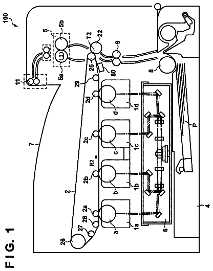
FIG. 1 is a diagram showing an example of a multifunctional peripheral according to an embodiment.
FIG. 2 is a diagram showing the example of the multifunctional peripheral according to the embodiment.
FIG. 3 is a diagram showing an example of a main menu screen according to the embodiment.
FIG. 4 is a diagram showing an example of a system menu screen according to the embodiment.
FIG. 5 is a diagram showing an example of a display input device according to the embodiment.
FIG. 6 is a diagram showing an example of an enlargement display setting screen according to the embodiment.
FIG. 7 is a diagram showing an example of a case where one of operation images is enlarged and displayed.
FIG. 8 is a diagram showing an example of a case where a plurality of operation images are enlarged and displayed.
FIG. 9 is a diagram showing an example of a case where an operation image located immediately below the track of a fingertip and operation images adjacent thereto in a first mode are enlarged and displayed.
FIG. 10 is a diagram showing an example of a case where the operation image located immediately below the track of the fingertip and operation images adjacent thereto in a second mode are enlarged and displayed.
FIG. 11 is a diagram showing an example of a case where an enlargement rate is changed according to the number of times the direction of movement of the fingertip is switched.
Detailed description
With the present disclosure, it is possible for a user who has a trembling fingertip to accurately touch a desired operation image. An embodiment of the present disclosure will be described below with reference to FIGS. 1 to 11 . A description will be given below using, as an example, a multifunctional peripheral 100 (which corresponds to a display input device) which is an example of a display input device 1 . However, individual elements such as configurations and arrangements described in the present embodiment are not intended to limit the scope of the disclosure but are simply an illustrative example.
(Multifunctional Peripheral 100 )
The multifunctional peripheral 100 according to the embodiment will be described with reference to FIGS. 1 and 2 . As shown in FIG. 1 , in the multifunctional peripheral 100 of the present embodiment, an operation panel 2 (indicated by broken lines in the figure) is provided in the front surface of the multifunctional peripheral 100 . In an upper portion, an original document transport portion 3 a and an image reading portion 3 b are provided. Within the multifunctional peripheral 100 , a print portion 4 (a paper feed portion 4 a , a transport portion 4 b , an image formation portion 4 c and a fixing portion 4 d ) for performing printing is provided.
The operation panel 2 includes a display panel 21 that displays the state of the multifunctional peripheral 100 , various types of messages and various types of setting screens. On the upper surface of the display panel 21 , a touch panel portion 22 is provided. The touch panel portion 22 is intended for detecting the position and the coordinates of a portion in the display panel 21 that is pressed. Based on the output of the touch panel portion 22 , the pressed operation image (image such as a soft key, a button, a tab or a check box) is recognized. In the operation panel 2 , a plurality of hard keys 23 such as a start key and a numeric keypad are also provided.
As the touch panel portion 22 , a touch panel portion is used which can detect a state in which a touch is not performed but a fingertip is moved close to the touch panel portion 22 . In the multifunctional peripheral 100 (the display input device 1 ) of the present embodiment, as the touch panel portion 22 , a capacitive type touch panel is used. The touch panel portion 22 of a type which includes a fingertip detection sensor such as an ultrasonic sensor or an optical sensor and which can detect that a fingertip is approaching the touch panel portion 22 may be adopted.
As shown in FIG. 2 , within the multifunctional peripheral 100 , a control portion 5 is provided. The control portion 5 controls the operations of the multifunctional peripheral 100 . The control portion 5 is connected via a bus or a signal line to individual portions such as the operation panel 2 , the original document transport portion 3 a. the image reading portion 3 b , the print portion 4 and a communication portion 51 . The control portion 5 recognizes the presence of the individual portions and individual devices. The control portion 5 controls the individual portions to control the operations of the multifunctional peripheral 100 such as a scan operation and a print operation. The control portion 5 includes circuits such as a CPU 5 a and an image processing portion 5 b.
A storage portion 6 stores various types of programs for the control of the multifunctional peripheral 100 and various types of data such as data, setting data and image data. The control portion 5 is connected to the communication portion 51 . The communication portion 51 is connected via a network, a public line or a cable to a computer 200 or a facsimile device 300 such that the communication portion 51 can communicate with them.
(Setting on Operation Panel 2 )
An example of the setting in the multifunctional peripheral 100 according to the embodiment will then be described with reference to FIGS. 3 and 4 .
The display panel 21 of the operation panel 2 displays various types of setting screens. The control portion 5 makes the display panel 21 switch the screens according to the operation on operation images such as a key, a button and a tab within the setting screen or the operation on the hard keys 23 arranged on the operation panel 2 .
A main menu screen S 1 shown in FIG. 3 is the highest screen in terms of hierarchy.
The main menu screen S 1 is a screen for selecting the type of job to be executed and the category of the setting. In an upper portion of the main menu screen S 1 , eight job selection keys K 0 are arranged to which icons (images) indicating the types of jobs that can be selected are attached. The display position of the job selection key K 0 corresponding to a desired job is touched, and thus it is possible to select the type of job such as copy or scan transmission. Then, the control portion 5 displays the setting screen of the selected job on the display panel 21 . In a lower portion of the main menu screen S 1 , a system related key group on a system setting (a setting related to the overall operation of the multifunctional peripheral 100 and a setting which is not accompanied by the execution of a job) is arranged.
The device information ion key K 1 of the system related key group is operated, and thus it is possible to check the remaining amount of toner and the remaining number of sheets. The help icon key K 2 is operated, and thus it is possible to display a help screen in which an operation method is explained.
The system menu key K 3 of the system related key group is operated, and thus the control portion 54 displays a system menu screen S 2 on a display portion 11 (see FIG. 7 ). The system menu screen S 2 is a screen for setting basic operations (behaviors and initial setting values) of the multifunctional peripheral 100 .
In the system menu screen S 2 , a plurality of system item keys K 4 to K 13 are arranged. The system item keys K 4 to K 13 include terms that indicate the categories of the system setting. The system item key K 4 of a “Common Setting” is operated, and thus it is possible to perform settings that are applied in common to individual functions, such as the setting of a screen which is first displayed when power is turned on, the setting of a notification sound when the operation panel 2 is operated (the operation panel 2 includes an unillustrated speaker) and the limitation of the number of sheets that can be printed at a time. The system item key K 5 of a “Copy” is operated, and thus it is possible to determine basic (default) behaviors on the copy function, such as whether or not the magnification is automatically changed when an original document whose size is different from that of the sheet stored is received. The system item key K 11 of a “Network” is operated, and thus it is possible to perform settings on the network, such as the IP address of the multifunctional peripheral 100 and a subnet mask. The description of details that can be set by the system item keys other than those described above will be omitted.
(Display Input Device 1 )
The display input device 1 according to the embodiment will then be described with reference to FIG. 5 .
In the multifunctional peripheral 100 , the display input device 1 is incorporated. The display input device 1 includes the operation panel 2 (the display panel 21 and the touch panel portion 22 ), the control portion 5 and the storage portion 6 . In the display input device 1 , that is, the multifunctional peripheral 100 , various types of settings can be performed while the screen is being seen.
The display panel 21 displays the setting screens and the operation images. The control portion 5 controls the display of the display panel 21 . The touch panel portion 22 is provided above the display panel 21 . The control portion 5 detects a touch position (coordinates) based on the output of the touch panel portion 22 . As shown in FIG. 5 , the touch panel portion 22 includes a sensor panel 22 a. The sensor panel 22 a includes transparent electrodes that are patterned. A protective film or a cover may be attached to the sensor panel 22 a. The sensor panel 22 a is capacitive type sensor panel. The touch panel portion 22 includes a detection IC 22 b that detects a variation in capacitance on the surface and that detects the touch position based on the position of the electrode whose capacitance is varied. The detection IC 22 b detects a variation in the capacitance of each electrode with a predetermined sampling rate. The detection IC 22 b determines whether the amount of variation in the capacitance of any one of the electrodes in the sensor panel 22 a is in a touch state and detects, when it falls within a predetermined range of values, the coordinates (position) of the touch position based on the position of the electrode whose capacitance is varied. The detection IC 22 b may be provided on the side of the control portion 5 .
The output (the result of the detection) of the detection IC 22 b is input to the control portion 5 . The control portion 5 recognizes the touch position(coordinates) based on the output of the detection IC 22 b of the touch panel portion 22 . The control portion 5 recognizes that an operation image which overlaps (is displayed on) the touch position (coordinates) is operated. Then, the control portion 5 displays, on the display panel 21 , the screen corresponding to the operation image that is operated.
The detection IC 22 b can detect a variation in capacitance that is lower than that at the time of touch. In other words, the detection sensitivity of the sensor panel 22 a and the detection IC 22 b is high. Hence, the detection IC 22 b detects, based on the position of the electrode where a variation in capacitance lower than that at the time of touch is produced, the position (coordinates) of a fingertip in a state in which the surface is not touched but the fingertip approaches the surface of the sensor panel 22 a , that is, in a close state in which the fingertip is closer to the sensor panel 22 a than a detectable distance. In other words, the detection IC 22 b detects the coordinates of the fingertip in the close state when the amount of variation in the capacitance of any one of the electrodes in the sensor panel 22 a falls within a range of values which are determined to be in the close state, that is, in the range of predetermined values.
The control portion 5 receives a notification from the detection IC 22 b. Hence, the control portion 5 can recognize, based on the output of the touch panel portion 22 , the close state in which the surface is not touched but the fingertip approaches the surface and the coordinates (position) of the fingertip in the close state. Although the size and the thickness of the finger vary between individuals, even in a state in which the finger is about one to a few centimeters away from the touch panel portion 22 , it is possible to detect and recognize the coordinates of the fingertip. While being in the close state, the detection IC 22 b continues to notify the position (coordinates) of the fingertip to the control portion 5 . In this way, the control portion 5 recognizes a movement path (track) of the coordinates (position) of the fingertip in the close state. The storage portion 6 stores track data D 1 (data indicating the movement progress of the fingertip (coordinates) in the screen being displayed; see FIG. 2 ).
(Determination of Swing State)
An example of a method of determining a swing state in the display input device 1 according to the embodiment will then be described
The control portion 5 determines whether or not in the close state, the fingertip is in a swing state in which the fingertip swings. The control portion 5 of the present embodiment determines, based on the recognized track of the fingertip in the close state, whether or not the fingertip is in the swing state.
When the user has a trembling fingertip, the fingertip may be moved so as to reciprocate. The movement of the fingertip caused by the trembling is characterized in that the direction of the movement of the fingertip is often changed and that the direction of the movement of the fingertip is changed at an angle of about 180 degrees.
Hence, the control portion 5 references the track data D 1 in the present display screen, and determines that the fingertip is in the swing state when the number of times the direction of the movement of the fingertip is switched within a predetermined determination period is more than a predetermined reference number. With consideration given to the reciprocation movement, the control portion 5 counts, in the switching of the direction of the movement of the fingertip in the close state, only the switching of the direction of the movement in which a variation in the angle in the direction of the movement falls within a predetermined range of angles (for example, more than 90 degrees but less than 270 degrees), with the result that a count value and the reference number may be compared with each other.
The determination period can be determined as necessary. For example, the determination period can be set to a period in which to go back only a predetermined time from the present time (time when whether or not the fingertip is in the swing state is determined). The predetermined time can be set to 1 to 5 seconds, and more preferably about 3 seconds. The reference number can also be determined as necessary. For example, the reference number can be determined to be about 3 to 15. For example, the control portion 5 determines that the fingertip is in the swing state when the fingertip is reciprocated about 10 times in 3 seconds. In other words, the control portion 5 automatically recognizes that the fingertip of the user who performs the operation trembles.
When the fingertip trembles, the movement distance of the fingertip from a changing point of the direction of the movement to a changing point may be short as compared with a flick operation or the like, and the swing width may be substantially constant. Hence, the control portion 5 references the track data D 1 and individually determines the distance (distance from the changing point of the direction of the movement to the changing point) from the switching of the direction of the movement of the fingertip to the subsequent switching. Then, the control portion 5 may use, as one of the conditions for determining that the fingertip is in the swing state, a fact that the absolute value of a difference between the individually determined distance and a distance in the preceding switching is equal to or less than a predetermined allowance value.
When the fingertip trembles, the region of the track (region that connects the outer circumferences of the changing points of the direction of the movement within the determination period) may be elongated, and its area may be prevented from being excessively large. Hence, the control portion 5 may use, as one of the conditions for determining that the fingertip is in the swing state, a fact that the area of a figure (the number of dots within the figure) connecting the outer circumferences of the coordinates of the switching points of the direction of the movement within the determination period is determined and that the determined area falls within a predetermined reference area.
Then, the control portion 5 determines that the fingertip is in the swing state when one of the conditions described above or a plurality thereof are satisfied. The control portion 5 periodically checks the track data D 1 to check whether or not the movement of the fingertip in the determination period (period in which to go back only a predetermined time from the present time) satisfies the conditions for determining that the fingertip is in the swing state. Then, the control portion 5 determines that the fingertip is in the swing state when it is determined that the determination conditions are satisfied.
Then, when the control portion 5 determines that the fingertip is in the swing state, the control portion 5 enlarges and displays the operation image for the user who has a trembling fingertip. Specifically, the control portion 5 enlarges and displays part or all of the operation image overlapping (located below) the track of the fingertip in the close state within a predetermined period. In this way, the operation image that the user is highly likely to desire to operate is enlarged and displayed.
(Aspect of Enlargement and Display)
An example of the enlargement and display of the operation image in the swing state in the display input device 1 according to the embodiment will then be described with reference to FIGS. 6 to 10 .
In the display input device 1 of the present embodiment, it is possible to previously determine, with the enlargement display setting screen S 3 of FIG. 6 , which one of the operation images within the screen is enlarged and displayed when the swing state is detected. The enlargement display setting screen S 3 can be displayed by performing a predetermined operation on the operation panel 2 .
In the enlargement display setting screen S 3 , a first mode key K 14 and a second mode key K 15 are displayed. Either of the first mode key K 14 and the second mode key K 15 is selected.
The first mode key K 14 corresponds to a first mode in which an operation image (first mode enlargement target image) where the time during which the fingertip is thereabove within a predetermined period is the longest is enlarged and displayed on the display panel 21 . When it is desired to enlarge and display the operation image in the first mode, the first mode key K 14 is operated (see FIG. 6 ).
The predetermined period can be determined as necessary. The predetermined period can be set to a period until the fingertip is determined to be in the swing state after the display of the present display screen or can be set to the determination period described above (the same is true in the following description).
The second mode key K 15 corresponds to a second mode in which a plurality of operation images (second mode enlargement target images) displayed below the track within the predetermined period are enlarged and displayed on the display panel 21 . When it is desired to enlarge and display the operation images in the second mode, the second mode key K 15 is operated (see FIG. 6 ).
When the fingertip is moved above a plurality of keys, in the second mode, a plurality of operation images are enlarged. When the first mode is selected, as compared with the case where the second mode is selected, the number of operation images which are enlarged is basically decreased. By contrast, when the second mode is selected, as compared with the case where the first mode is selected, the number of operation images which are enlarged is basically increased.
Below the first mode key K 14 , a first check box C 1 is provided. When the first check box C 1 is checked, the control portion 5 enlarges and displays, on the display panel 21 , together with the first mode enlargement target image, the operation image adjacent to the first mode enlargement target image. When the first check box C 1 is not checked, only one operation image (the first mode enlargement target image) is enlarged and displayed on the display panel 21 , and the display size of the operation image adjacent to the first mode enlargement target image is not changed.
Below the second mode key K 15 , a second check box C 2 is provided. When the second check box C 2 is checked, the control portion 5 enlarges and displays, on the display panel 21 , together with the second mode enlargement target image, the operation image adjacent to the second mode enlargement target image. When the second check box C 2 is not checked, only the second mode enlargement target image is enlarged and displayed, and the display size of the operation image adjacent to the second mode enlargement target image is not changed.
As described above, in the display input device 1 , which one of the operation images within the display screen is enlarged and displayed can be determined by the user. The aspect of the actual enlargement and display of the operation image will be described below. An example when the operation image is enlarged and displayed in the system menu screen S 2 (see FIG. 4 ) will be described below (likewise, in the main menu screen S 1 , the operation image is enlarged and displayed).
(First Mode)
An example where in the first mode, the operation image is enlarged and displayed when the operation image adjacent thereto is not enlarged (when the first check box C 1 is not checked) will first be described with reference to FIG. 7 .
The figure in the upper portion of FIG. 7 shows a state before the control portion 5 determines that the fingertip is in the swing state. As an example of the screen displayed, the system menu screen S 2 is used. In other words, the operation image is not enlarged and displayed, and a normal display state of the system menu screen S 2 is shown. The figure in the upper portion of FIG. 7 shows that the fingertip of the user swings above the system item key K 5 of the “Copy” and the system item key K 7 of a “Document Box”. In the figure in the upper portion of FIG. 7 , an example of the position of the fingertip (hand) in the close state is indicated by a hand-shaped broken-line figure. An example of the direction in which the fingertip swings is indicated by a framed white arrow.
When the control portion 5 determines that the fingertip is in the swing state, the control portion 5 enlarges and displays, on the display panel 21 , an operation image (the first mode enlargement target image) where the time during which the fingertip is thereabove within the predetermined period is the longest. The figure in the lower portion of FIG. 7 shows an example where the system item key K 7 of the “Document Box” is enlarged and displayed as the first mode enlargement target image.
Since the operation image is enlarged, even when the fingertip trembles, it is possible to easily touch the interior of the region of the operation image. When the region within the enlarged operation image is touched, the control portion 5 recognizes that the enlarged operation image is operated, and displays, on the display panel 21 , a screen corresponding to the enlarged operation image.
(Second Mode)
An example where in the second mode, the operation image is enlarged and displayed when the operation image adjacent thereto is not enlarged (when the second check box C 2 is not checked) will then be described with reference to FIG. 8 .
The figure in the upper portion of FIG. 8 shows a state before the control portion 5 determines that the fingertip is in the swing state. As an example of the screen displayed, the system menu screen S 2 is used. In other words, the operation image is not enlarged and displayed, and the normal display state of the system menu screen S 2 is shown. The figure in the upper portion of FIG. 8 shows that the fingertip of the user swings above the system item key K 5 of the “Copy” and the system item key K 7 of a “Document Box”. In the figure in the upper portion of FIG. 8 , an example of the position of the fingertip (hand) in the close state is indicated by a hand-shaped broken-line figure. An example of the direction in which the fingertip swings is indicated by a framed white arrow.
When the control portion 5 determines that the fingertip is in the swing state, the control portion 5 enlarges and displays, while displaying the display screen (the system menu screen S 2 in the example of FIG. 8 ), on the display panel 21 , the operation image (the second mode enlargement target image) displayed immediately below the track of the fingertip within the predetermined period.
When a plurality of operation images located immediately below the track of the fingertip in the close state within the predetermined period are present, all of them may be enlarged and displayed or only part thereof may be enlarged and displayed. The maximum number of operation images that are enlarged and displayed is previously determined, and when the number of operation images located immediately below the track is equal to or less than the maximum number, the control portion 5 enlarges and displays all of the operation images on the display panel 21 . When the number of operation images located immediately below the track exceeds the maximum number, the number of operation images that are enlarged and displayed by the control portion 5 may be limited to the maximum number of operation images. In this case, it is possible to determine, as necessary, what operation images are enlarged. For example, the control portion 5 selects, enlarges and displays, as the second mode enlargement target images, up to the maximum number of operation images among the operation images located immediately below the track, in decreasing order of the time during which the fingertip is present thereabove.
The figure in the lower portion of FIG. 8 shows an example of the state in which all the operation images located immediately below the track are enlarged and displayed. The figure in the lower portion of FIG. 8 shows an example where the system item key K 5 of the “Copy” and the system item key K 7 of the “Document Box” are enlarged and displayed.
A plurality of operation images overlapping the track are highly likely to include the operation image that the user desires to operate. In this way, it is possible to enlarge and display only the operation panel that the user is highly likely to desire to operate.
(Enlargement of Adjacent Operation Images)
Enlargement of operation images (hereinafter referred to as “adjacent operation images”) adjacent to the first mode enlargement target image or the second mode enlargement target image will then be described with reference to FIGS. 9 and 10 .
The figures in the upper portion of FIGS. 9 and 10 show a state before the control portion 5 determines that the fingertip is in the swing state. As an example of the screen displayed, the system menu screen S 2 is used. In other words, the operation image is not enlarged and displayed, and the normal display state of the system menu screen S 2 is shown.
The figure in the upper portion of FIG. 9 shows that the fingertip of the user swings above the system item key K 5 of the “Copy” and the system item key K 7 of the “Document Box”. In the figure in the upper portion of FIG. 9 , an example of the position of the fingertip (hand) in the close state is indicated by a hand-shaped broken-line figure. An example of the direction in which the fingertip swings is indicated by a framed white arrow.
As shown in the figure in the lower portion of FIG. 9 , when the first check box C 1 is checked, the control portion 5 enlarges and displays, on the display panel 21 , the first mode enlargement target image (the operation image where the time during which the fingertip stays thereabove within the predetermined period is the longest) and the operation images adjacent to the first mode enlargement target image.
In the example of FIG. 9 , the operation image where the time during which the fingertip stays thereabove is the longest is the system item key K 7 of the “Document Box”. FIG. 9 shows the state in which the system item key K 5 of the “Copy”, the system item key K 6 of a “Send” and the system item key K 9 of a “Printer” adjacent to the “Document Box” in the up/down direction and in the left/right direction are enlarged. The system item key K 4 of the “Common Setting” and the system item key K 8 of a “Report” obliquely adjacent thereto may be enlarged and displayed.
The figure in the lower portion of FIG. 10 shows an example of a case where the operation images adjacent to the second mode enlargement target image are also enlarged and displayed (an example of a case where the second check box C 2 is checked). The figure in the lower portion of FIG. 10 shows an example where the control portion 5 enlarges and displays, on the display panel 21 , the operation images (the second mode enlargement target images) overlapping the track when seen from above and the operations adjacent thereto.
The figure in the upper portion of FIG. 10 shows that the fingertip of the user swings above the system item key K 4 of the “Common Setting” and the system item key K 5 of the “Copy”. In the figure in the upper portion of FIG. 10 , an example of the position of the fingertip (hand) in the close state is indicated by a hand-shaped broken-line figure. An example of the direction in which the fingertip swings is indicated by a framed white arrow.
In the example of FIG. 10 , the operation images overlapping the track are the system item key K 4 of the “Common Setting” and the system item key K 5 of the “Copy”. The figure in the lower portion of FIG. 10 shows the state in which the system item key K 6 of the “Send” and the system item key K 7 of the “Document Box” adjacent to the system item key K 4 of the “Common Setting” and the system item key K 5 of the “Copy” in the up/down direction or in the left/right direction are enlarged.
As described above, the operation images adjacent to the operation image located below the track of the fingertip in the close state are also enlarged, and thus the operation images enlarged and displayed include the key that the user desires to operate almost without fail. Hence, even when the fingertip trembles, the user can touch the desired operation image without fail.
(Enlargement Rate of Operation Image)
An enlargement rate in the enlargement of the operation image according to the embodiment will then be described with reference to FIGS. 7, 8 and 11 . FIG. 11 is a diagram showing an example of a case where an enlargement rate is changed according to the number of times the direction of the movement of the fingertip is switched.
It is possible to determine, as necessary, to what degree the operation image is enlarged. The control portion 5 may apply a predetermined fixed enlargement rate (for example, any value between 120 and 300%), enlarge the operation image in the up/down direction and in the left/right direction only by the fixed enlargement rate and thereby enlarge and display the operation image.
As the number of times the direction of the movement of the fingertip is switched in the close state in the predetermined period is increased, the control portion 5 may increase the enlargement rate in the enlargement and display. When the fingertip trembles significantly, the number of times the switching is performed is increased. When the fingertip trembles significantly, a large number of users have difficulty in performing accurate touching. Hence, when the control portion 5 recognizes that the fingertip trembles significantly, the control portion 5 may apply a high enlargement rate among a plurality of types of fixed enlargement rates to enlarge the width of the operation image in the up/down direction and the width in the left/right direction by the applied enlargement rate.
In this case, the enlargement rates corresponding to the number of times the direction of the movement of the fingertip is switched are stored as data (switching number data D 2 ) in the storage portion 6 (see FIG. 2 ). In the switching number data D 2 , as the number of times the switching is performed is increased, a higher enlargement rate is defined. In this case, the control portion 5 determines the enlargement rate based on the actually counted number of times the switching is performed and the switching number data D 2 .
In the display input device 1 , with a third check box C 3 provided in the enlargement display setting screen S 3 , it is possible to set whether or not the enlargement rate is increased as the fingertip trembles more significantly. When the third check box C 3 is not checked, the control portion applies the predetermined fixed enlargement rate to enlarge and display the operation image. On the other hand, when the third check box C 3 is checked, the control portion determines the enlargement rate based on the counted number of times the switching is performed and the switching number data D 2 .
The display input device 1 may determine the enlargement rate according to the breadth of the range of the track of the fingertip in the close state. In this case, the control portion 5 determines the swing range B of the fingertip based on the track. Then, the control portion 5 enlarges and displays the operation image on the display panel 21 such that the width of the operation image after being enlarged and displayed in the up/down direction is wider than the width of the determined swing range B in the up/down direction and that the width of the operation image after being enlarged and displayed in the left/right direction is wider than the width of the determined swing range B in the left/right direction.
The control portion 5 first checks the original size (the number of dots in each of the up/down direction and the left/right direction) of the operation image to be enlarged and displayed. The control portion 5 determines the swing range B and checks the width (the number of dots) of the swing range in the up/down direction and the width in the left/right direction. Here, the swing range B can be determined as necessary.
The description continues in the full USPTO document.
 Lapsed, fee not paid2 drawings