 Lapsed, fee not paid8 drawings
Hardware & Electronics · US 9,818,576 B2
Electron microscope
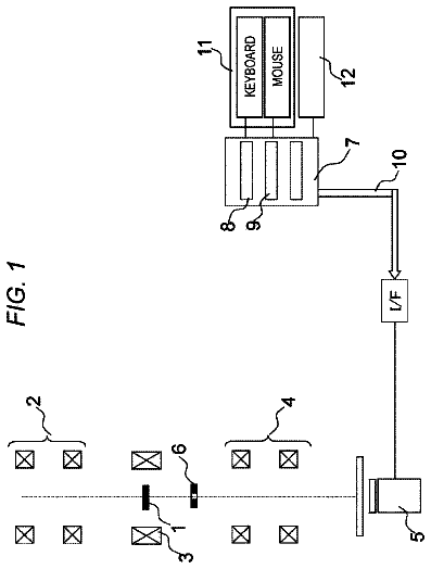
To improve the workability of the task of adjusting the position of a limit field diaphragm.
US 9,818,593 B2 · Assignee: University of Maine System Board of Trustees · Inventors: Solouki; Touradj et al.
Sheet 1 of 18 from the published document. All sheets in the USPTO PDF
Methods and systems for performing ionization, including applying radio frequency energy to a chemical compound so that at least one ion of the compound or of a compound fragment is generated, and detecting at least one such ion.
A variety of technologies for the detection and/or analysis of chemical compounds or entities rely on or require detection of ions (e.g., ionic forms of the detected compounds or entities). The present disclosure provides new methods and systems for achieving ionization of organic compounds. In particular, the present disclosure describes radio-frequency ionization (RFI) of organic materials.
1 of 18 drawing sheets so far from the published document, cropped to the drawing. Every sheet is in the USPTO PDF.
What the patent claimed, word for word. All of it is now free to use.
A variety of technologies for the detection and/or analysis of chemical compounds or entities rely on or require detection of ions (e.g., ionic forms of the detected compounds or entities). The present disclosure provides new methods and systems for achieving ionization of organic compounds. In particular, the present disclosure describes radio-frequency ionization (RFI) of organic materials.
Among other things, the present disclosure encompasses the surprising insight that ions of chemical compounds (e.g., organic compounds), or fragments thereof, can be generated with high efficiency through application of radio frequency energy to the compounds. For example, in some embodiments, a radio frequency signal is applied to one or more ion guide rods to which a sample comprising the compound of interest is exposed. In some embodiments, provided ionization systems and techniques are particularly useful in methodologies and/or systems involving the detection of entities with mass spectrometry.
Among other things, the present invention encompasses the recognition that many common ionization sources typically utilized in association with mass spectrometry technologies can result in undesirable background noise and/or pressure, for example as can be caused by outgassing of heated or energized electrical components. In some embodiments, use of RFI technologies as provided by the present disclosure reduces, avoids, or eliminates such undesirable background noise and/or pressure. One advantage provided by certain embodiments of the present invention is that use of RFI with mass spectroscopy achieves dramatically improved signal-to-noise, on the order of at least a six-fold improvement, when compared with certain common ionization techniques. Additionally, by altering the duration of emission at the source, RFI permits control of the degree and extent of parent ion fragmentation, allowing use of RFI to cause both “soft” and “hard” ionization.
In some embodiments, the present invention provides methods including steps of applying radio frequency (RF) energy to a chemical compound so that at least one ion of the compound or of a compound fragment is generated, and detecting at least one such ion. In some embodiments, such application of RF energy is performed in a chamber. In some embodiments, such application of RF energy involves applying a RF signal to at least one ion guide rod that is part of an ion guide assemble positioned relative to a pair of trapping plates that define first and second ends of a cell, the first of which such trapping plates has an opening allowing passage of ions therethrough, so that a gap is defined between an exposed face of the at least one guide rod and the first trapping plate so that, when a sample comprising the chemical compound passes through the opening, ionization of the compound occurs. In some embodiments, fragmentation of the compound also occurs, such that ionized fragments are generated.
Thus, in some embodiments, the present invention provides methods for performing ionization including steps of providing a chamber, introducing one or more chemical compounds to the chamber, applying radiofrequency energy to the one or more chemical compounds so that at least one ion of the compound or of a compound fragment is generated, and detecting at least one such ion.
Alternatively or additionally, in some embodiments, the present invention provides methods for performing ionization, including providing a pair of trapping plates located within a chamber, wherein the pair of trapping plates define a first end and a second end of a cell, the first end trapping plate comprising at least one opening allowing passage of ions therethrough; and applying a radio frequency (RF) signal to an ion guide assembly comprising at least one ion guide rod, wherein the ions are formed in a gap between an exposed end of the at least one ion guide rod and the first end trapping plate.
According to various embodiments, the present invention provides for ionization systems including a source of radio frequency (RF) energy for providing power for production of ions, a chamber, a pair of trapping plates located within the chamber, wherein the pair of trapping plates defines a first end and a second end of a cell, the first end trapping plate comprising at least one opening allowing passage of ions therethrough; and an ion guide assembly comprising at least one ion guide rod, wherein the ions are formed in a gap between an exposed end of the at least one ion guide rod and the first end trapping plate. In some such embodiments, when a chemical compound is ionized (and optionally fragmented) in a gap and passes through the opening for detection.
In some embodiments, the frequency of the RF signal applied to the at least one ion guide rod may be within a range between about 1.0 MHz and about 100 MHz, inclusive. For example, in some embodiments, such range has a lower bound of about 2.0 MHz, about 3.0 MHz, about 4.0 MHz, about 4.5 MHz, about 5.0 MHz, about 5.5 MHz, about 6.0 MHz, about 10. MHz, about 12 MHz, about 12.5 MHz, about 13 MHz, or about 20 MHz and an upper bound of about 95 MHz, about 90 MHz, about 80 MHz, about 70 MHz, about 60 MHz, about 50 MHz, about 40 MHz, about 30 MHz, about 20 MHz, about 10 MHz, about 8 MHz, about 6.5 MHZ, or about 6 MHz, the upper bound being larger than the lower bound. In some embodiments, the upper bound is greater than 7.0 MHz. In some embodiments, the lower bound is below 4 MHz.
In various embodiments, the gap between the exposed end of the at least one ion guide rod and the first end trapping plate is between about 0.01 μm and about 4 mm. For example, in some embodiments, such range has a lower bound of about 0.1 μm, about 1.0 μm, about 0.01 mm, about 0.05 mm, about 1.0 mm, about 1.5 mm, about 2.0 mm, or about 2.5 mm and an upper bound of about 4 mm, about 3.5 mm, about 3.0 mm, about 2.5 mm, or about 2.0 mm, the upper bound being larger than the lower bound. In some embodiments, the size of the gap is selected in accordance with the frequency of the RF signal to be applied to the at least one rod. In some embodiments, use of a longer wavelength (i.e. lower frequency) and lower voltage RF signal is associated with a smaller gap than use of a shorter wavelength (i.e. higher frequency) and higher voltage RF signal.
In some embodiments, the ion guide assembly comprises at least one ion guide rod. In some embodiments, the ion guide assembly comprises a plurality of ion guide rods for example, two, three, four, five, six, seven, eight, or more ion guide rods. In some embodiments, the plurality of ion guide rods are arranged symmetrically around a central axis, which runs longitudinally parallel to the plurality of ion guide rods. In some embodiments, the at least one opening in the first trapping plate is located out of alignment with the central axis of the ion guide assembly.
In some embodiments, the at least one opening in the first trapping plate has a diameter between about 1 nm and about 1.0 cm. For example, in some embodiments, such range has a lower bound of about 1 nm, about 1 μm, about 0.1 cm, about 0.2 cm, about 0.3 cm, about 0.4 cm, about 0.5 cm, or about 0.6 cm and an upper bound of about 1 cm, about 0.9 cm, about 0.8 cm, about 0.7 cm, about 0.6 cm, about 0.5 cm, about 0.1 cm, or about 10 μm, the upper bound being larger than the lower bound. In some embodiments, the at least one opening is larger than 1.0 cm.
In some embodiments, methods provided by the present invention comprise introducing an analyte (i.e., comprising one or more chemical compounds) into a chamber. In some embodiments, the chamber is arranged and constructed to support application of a vacuum. In some embodiments, the analyte may be introduced through an aperture in a wall defining a boundary of the chamber. In some embodiments, the aperture may be or comprise a port, valve, or other structure allowing for controlled introduction of an analyte into the vacuum chamber. In some embodiments, the analyte is in the form of a gas when introduced into the chamber. In some embodiments, the analyte is in the form of a liquid when introduced into the chamber. In some embodiments, the analyte is in the form of a solid when introduced into the chamber.
It is contemplated an analyte, after introduction into the chamber, may have any pressure that would provide one or more analyte molecules, according to various embodiments. In some embodiments, the analyte, after introduction into the chamber, has a partial pressure between about 1×10.sup.−12 torr and about 1×10.sup.−3 torr. For example, in some embodiments, such range has a lower bound of about 1×10.sup.−11, about 1×10.sup.−10, about 1×10.sup.−8, about 1×10.sup.−6, or about 1×10.sup.−4, and an upper bound of about 1×10.sup.−4, about 1×10.sup.−5, about 1×10.sup.−6, about 1×10.sup.−8, about 1×10.sup.−10, or about 1×10.sup.−11, the upper bound being larger than the lower bound.
In some embodiments, systems and methods provided by the present invention include detecting one or more ions (e.g., of the chemical compound and/or of one or more fragments thereof). In some embodiments, such detection comprises mass spectrometry (MS)(e.g., comprises collecting at least one mass spectrum). In some embodiments, the MS is or comprises quadrupole MS, Fourier Transform Ion Cyclotron Resonance (FT-ICR) MS, and/or Time-Of-Flight (TOF) MS. Also, all other types of mass spectrometers, ion mobility devices, and ion detectors are contemplated as within the scope of the present invention and may be used for ion detection.
According to some embodiments, RF signal is applied to the at least one ion guide rod for a period of time that lasts for between about 0.01 ms and about 5.0 s. For example, in some embodiments, such range has a lower bound of about 0.01 ms, about 0.1 ms, about 1.0 ms, about 10 ms, 0.05 s, about 0.1 s, about 0.5 s, about 1.0 s, or about 1.5 s and an upper bound of about 4.5 s, about 4 s, about 3.5 s, about 3 s, about 2.5 s, about 2.0 s, about 1.5 s, about 1.0 s, or about 0.5 s, the upper end being larger than the lower bound. In some embodiments, the period of time is sufficient to yield mass spectra resembling hard ionization of the analyte. In some embodiments, the period of time is sufficient to yield mass spectra resembling soft ionization of the analyte. In some embodiments, the RF signal is applied to the at least one ion guide for more than 5.0 seconds.
In some embodiments, a wire ion guide is positioned between the first and second end trapping plates, wherein the wire ion guide is electrically isolated from the cell, and a voltage is applied during ion excitation and/or detection. It is contemplated the wire may be comprised of any conducting material. In some embodiments, the wire may be comprised of a metal material such as for example, copper, silver, gold, or another appropriate metal. In some embodiments, the voltage is pulsed.
In some embodiments, the RF signal is applied by an RF source in operational association with the at least one ion guide rod to which it is applied. According to various embodiments, the RF source is located in the chamber.
As used in this application, the terms “about” and “approximately” are used as equivalents. Any numerals used in this application with or without about/approximately are meant to cover any normal fluctuations appreciated by one of ordinary skill in the relevant art.
Other features, objects, and advantages of the present invention are apparent in the detailed description that follows. It should be understood, however, that the detailed description, while indicating embodiments of the present invention, is given by way of illustration only, not limitation. Various changes and modifications within the scope of the invention will become apparent to those skilled in the art from the detailed description.
The foregoing and other objects, aspects, features, and advantages of the present disclosure will become more apparent and better understood by referring to the following description taken in conjunction with the accompanying figures in which:
FIG. 1 shows an exemplary schematic of an ionization quadrupole ion guide rod assembly adjacent to a quadrupole trapping plate, together defining an ionization region wherein RF energy flows.
FIG. 2A depicts a schematic representation of an ion cyclotron resonance cell, wherein the quadrupole trapping plate does not contain any openings to quadrupole ion guide rod assembly.
FIG. 2B depicts a schematic representation of an ion cyclotron resonance cell, wherein the quadrupole trapping plate has only a single on-axis opening to the ion cyclotron resonance cell, wherein on-axis means aligned with a central axis of the ion guide assembly.
FIG. 2C shows an exemplary RFI/FT-ICR mass spectra for acetone generated using an ion cyclotron resonance cell of either the configuration of FIG. 2A , wherein the quadrupole trapping plate does not have an opening to the cell, or the configuration of FIG. 2B , wherein the quadrupole trapping plate has only a single on-axis opening to the cell.
FIG. 3A depicts a schematic representation of an exemplary ion cyclotron resonance cell, wherein the quadrupole trapping plate includes a center opening and four off-axis openings to the quadrupole ion guide rod assembly.
FIG. 3B depicts a schematic representation of an exemplary ion cyclotron resonance cell, wherein the quadrupole trapping plate includes only four off-axis openings to the quadrupole ion guide rod assembly.
FIG. 3C shows an exemplary RFI/FT-ICR mass spectra for acetone generated using an ion cyclotron resonance cell of either the configuration of FIG. 3A or the configuration of FIG. 3B .
FIG. 4 shows a schematic representation of an exemplary cylindrical ion cyclotron resonance cell with a wire ion guide positioned between the first (quadrupole or QTP) and second (filament or end) trapping plates of the cylindrical ion cyclotron resonance cell.
FIG. 5A shows an exemplary RFI/FT-ICR mass spectrum of acetone acquired without using a wire ion guide positioned between the first and second trapping plates during off-axis ion introduction.
FIG. 5B shows an exemplary RFI/FT-ICR mass spectrum of acetone acquired using the wire ion guide positioned between the first and second trapping plates during off-axis ion introduction.
FIG. 6A shows an exemplary RFI/FT-ICR mass spectra of acetone with an ionization pulse time duration of 900 ms and frequency of 6.5 MHz about 200 V.sub.bp.
FIG. 6B shows an exemplary EI/FT-ICR mass spectra of acetone with an ionization pulse time duration of 900 ms and electron energy of 70 eV.
FIG. 7 depicts a graph of RFI operating conditions that can yield mass spectra resembling either hard and/or soft or chemical ionization (CI) outcomes.
FIG. 8 depicts an exemplary schematic view of an insulating sleeve positioned on the end of the quadrupole rods proximal to quadrupole trapping plate including four off-axis openings and one on-axis opening.
FIG. 9A shows an exemplary RFI/FT-ICR mass spectrum of cyclic poly dimethyl siloxane (PDMS) compounds of a type 5 Varflex electrically insulating sleeve.
FIG. 9B shows an exemplary RFI/FT-ICR mass spectrum of the PDMS compounds shown in 9 A, having an expanded view of the spectra between 354 m/z and 359 m/z.
FIG. 10 shows an exemplary RFI/FT-ICR mass spectrum of heptatriene generated according to certain embodiments.
FIG. 11 shows an exemplary RFI/FT-ICR mass spectrum of chlorodibromomethane generated according to certain embodiments.
FIG. 12 shows an exemplary RFI/FT-ICR mass spectrum of perfluorotributylamine generated according to certain embodiments.
FIG. 13 shows an exemplary RFI/FT-ICR mass spectrum of a hydrocarbon mixture generated according to certain embodiments.
FIG. 14 shows an exemplary RFI/FT-ICR mass spectrum of VOCs from an aqueous phase of bio-oil derived from slow pyrolysis of pine shavings (PS) generated according to certain embodiments.
FIG. 15 shows an exemplary RFI/FT-ICR mass spectrum of volatile organic compounds (VOCs) from an oily phase of bio-oil derived from slow pyrolysis of pine shavings (PS).
FIG. 16 shows an exemplary RFI/FT-ICR mass spectrum of a commercially available gasoline sample.
FIG. 17 depicts an expanded view of an exemplary m/z range 100.9 to 101.2 for RFI/FT-ICR mass spectrum of an aqueous phase of a bio-oil derived from slow pyrolysis of pine shavings (PS).
FIG. 18 depicts an expanded view of an exemplary m/z range 100.9 to 101.2 for RFI/FT-ICR mass spectrum of an oily phase of a bio-oil derived from slow pyrolysis of pine shavings (PS).
The present invention provides, among other things, systems and methods for using radio frequency energy to ionize an analyte (e.g., a compound within a chemical mixture/sample). The present invention is based, in part, on the surprising discovery that radio frequency energy can be used as an energy source for ionization of analytes, including both “soft” ionization as well as “hard” ionization. In some embodiments, radio frequency ionization (RFI) in mass spectrometry has surprisingly demonstrated at least a six-fold improvement in signal-to-noise ratio when compared with other ionization techniques such as electron impact ionization. In some embodiments, RFI of a target analyte occurs in an ionization region outside, but adjacent to, a portion of the mass spectrometer dedicated to separation and detection of analyte ions. In some embodiments, using RFI is advantageous as compared to traditional ionization energy sources, such as electron impact ionization (EI), because such use allows for a reduction or even elimination of the pressure and background noise caused by outgassing of heated or energized electrical components of common ionization sources and techniques. Additionally, by adjusting the emission duration at the RF source, it is possible to control the degree and extent of parent ion fragmentation.
Ionization Sources and Methods in General
Ionization is a process by which an atom or molecule obtains either a negative charge by acquiring an electron or a positive charge by losing an electron. Ionization may also occur when an atom or molecule combines with another atom or molecule that already has a charge. Negatively charged ions may be generated by a process known as electron capture ionization. Typically, a negative ionization occurs through a collision between an electron and an atom of a molecule, resulting in the electron being trapped by the molecule. Typically, a positively charged ion is formed when sufficient energy is transferred to a bound electron of an atom of a molecule such that the electron is freed from the molecule. The threshold energy required to remove an electron on a particular atom of a particular molecule is referred to as its ionization potential. See “MASS SPECTROMETRY: Principles and Applications” (1996, John Wiley & Sons) co-authored by E. D. Hoffmann, J. Charette, V. Stroobant, Page 288, which is hereby incorporated by reference in its entirety.
While ions form naturally, under certain circumstances it is desirable to facilitate ionization using a form of directed energy. Various methods and sources for ionization exist, including: corona discharge, electron impact ionization, chemical ionization, glow discharge ionization, atmospheric pressure chemical ionization, atmospheric pressure photoionization, electrospray ionization, matrix-assisted laser desorption ionization, and vacuum laser ionization. Applications for ionization include mass spectrometry, ion mobility spectrometry, and determination of molecular weight and/or bond energy of a target substance. Mass spectrometry in particular is a powerful analytical technique for performing chemical and molecular analysis.
The following equation provides a generic representation of positive photoionization of a molecule, M: M+hν.fwdarw.M+⋅+e− Equation 1 While depicted in Equation 1 as light, the energy source may be an ion, a radioactive element or another electron. A wide variety of ionization techniques are known, including: corona discharge, atmospheric pressure photoionization, dopant-assisted atmospheric pressure photoionization, atmospheric pressure chemical ionization, radioactive source ionization, laser desorption ionization, electron impact ionization, chemical ionization, glow discharge, inductively coupled plasma, electrospray ionization, spark ionization, and matrix-assisted laser desorption electrospray ionization, among others.
The present invention is based, at least in part, on the use of radio frequency energy to cause ionization of one or more analytes, for example, one or more chemical compounds. While the present disclosure focuses primarily on ionization as used with mass spectrometry, ionization is applicable in other techniques and analytical methods, for example, bond energy determination, in which the bond strength of a chemical bond is calculated as the heat required to break one mole of molecules into their individual atoms, or the treatment of certain diseases, such as cancer. It is contemplated that provided radiofrequency ionization (RFI) methods and systems may be used in any known process or system in which ionization provides a benefit or advantage.
Mass Spectrometry
According to various embodiments, provided methods and systems may be used in conjunction with one or more mass spectrometry techniques. Mass spectrometry is an analytical technique used to determine the chemical composition of a substance by analyzing and quantifying its component atoms and molecules. In mass spectrometry, the chemical composition of a target analyte is determined by assessing the mass and concentration of the components of the analyte. Mass spectrometry is broadly applicable across industry and for research applications, including, but not limited to: 1) biotechnology, where it may be used to analyze proteins and peptides, 2) in the pharmaceutical industry, where it may be used to develop new drugs, 3) in medicine, where it is used for testing and screening (e.g. disease biomarker detection), 4) in geology, where it is used in the study oil composition, 5) environmental engineering, where it is used to analyze water and food samples for contamination, and 6) forensics, where it is used to detect the presence of certain materials such as residue from explosives. Mass spectrometry, as a technique, encompasses three major components: ionization of a vaporized analyte, separation of the components by mass to charge ratio, and detection and plotting of the result for analysis.
In mass spectrometry, a target analyte is vaporized and bombarded by a high energy emission. Exposure of an analyte to an ionization source results in the formation of molecular fragments whose masses can be directly measured. The molecular weight of a substance is calculable following formation of the constituent molecular ion peaks. The mass of the ions formed lends to identification of the element through analysis of the mass-to-charge ratio, and the total number of ions formed is a reflection of the concentration.
A variety of known mass spectrometry systems and techniques are known, including time of flight mass spectrometry, quadrupole mass spectrometry, and ion cyclotron resonance mass spectrometry. For purposes of clarity, much of the present disclosure will be directed to ion cyclotron resonance mass spectrometry for comparison of RFI to other ionization sources. However, it is contemplated as within the scope of the present invention that RFI is equally applicable to other mass spectrometry techniques. Exemplary Fourier transform ion cyclotron resonance (FT-ICR) spectrometers contemplated as within the scope of the present invention include those described by Comisarow, et al. U.S. Pat. No. 3,937,955, the disclosure of which is hereby incorporated by reference in its entirety. See also “MASS SPECTROMETRY: Principles and Applications” (1996, John Wiley & Sons).
A wide array of mass spectrometry systems are known and each is designed and assembled with an eye toward balancing the perceived benefits and drawbacks of the various techniques and systems for performing each of: ion formation, mass separation, and detection. Achieving optimum analytical performance in mass spectrometry depends at least in part on the ionization method and performance thereof. Of the previously known ionization sources available, each suffers from challenges associated with the introduction of sample analytes causing increased background pressure, outgassing of electrical components during operation, delays due to the time required to replace electrical components damaged due to operation at high pressures, and, importantly the presence of chemical noise during analysis directly impacting the results and analysis. For example, electron impact ionization (EI) gives a high degree of fragmentation, yielding highly detailed mass spectra, however, EI is not suitable for coupling to high performance liquid chromatography (HPLC) systems, because, at atmospheric pressure, the filaments used to generate electrons burns out rapidly. In some embodiments, the present invention provides methods and systems that overcome one or more of these challenges.
By designing mass spectrometers that can determine the mass-to-charge (m/z) values accurately to four decimal places or more, it is possible to distinguish different formulas having the same nominal mass. Achieving optimum analytical performance in mass spectrometry depends at least in part on the efficiency of the ionization method. Generally, ionization methods are clustered into two major categories, hard and soft ionization approaches. Typically, hard ionization methods yield extensive ion fragmentation, while soft ionization methods tend to provide significantly less fragmentation. Exemplary hard ionization methods include: electron impact ionization, .sup.252Cf desorption, and laser desorption. In some applications, hard ionization methods are advantageous because they offer additional functional group and structural information. However, often it is beneficial to avoid high ion fragmentation, to simplify the mass spectral complexities, and increase the signal-to-noise ratio for unknowns through the identification of intact molecular ions. Therefore, soft ionization methods such as chemical ionization (CI), field desorption, matrix-assisted laser desorption/ionization (MALDI), and electrospray ionization (ESI) are valuable methods to produce intact molecular ions of small molecules and/or macromolecular biopolymers.
As is described herein, RF energy can be used to provide of either hard ionization or soft ionization, in some embodiments, the type of ionization is determined by the degree of exposure to RF energy, for example, the length of time or range of frequencies and voltages an analyte is exposed to RF energy.
Radio Frequency Ionization
The present invention provides, in some embodiments, methods including the steps of applying radio frequency energy to a chemical compound so that at least one ion of the compound or of a compound fragment is generated, and detecting at least one such ion.
The present invention also provides, in some embodiments, methods of performing ionization including the steps of providing a chamber, introducing one or more chemical compounds to the chamber, applying radio frequency energy to the one or more chemical compounds so that at least one ion of the compound or of a compound fragment is generated, and detecting at least one such ion.
Any of a variety of chemical compounds/analytes may be used in accordance with provided methods and systems. As used herein, the term “chemical compound” means any substance consisting of two or more different chemical elements. Generally, any chemical compound that is susceptible to ionization with radio frequency energy is contemplated as within the scope of the present invention. In some embodiments, a chemical compound may be an organic (i.e. carbon containing) compound. Exemplary chemical compounds include, but are not limited to: petrochemicals and biological molecules (e.g., molecules derived or isolated from a living organism).
It is expected that provided methods and systems are compatible with a wide variety of chemical compounds/analytes in various states of matter. In some embodiments, the one or more chemical compounds is a solid. In some embodiments, the one or more chemical compounds is a liquid. In some embodiments, the one or more chemical compounds is a gas. Across various embodiments, RFI/FT-ICR MS can successfully generate ions from various classes of compounds, for example, small molecules, volatile polar compounds, non-polar compounds, halogenated organic molecules, very high molecular weight heavy petroleum/gas samples, complex biologics, proteins, peptides, lipids, electrically conducting species, electrically non-conducting species, ad electrically insulating species, among others.
Detection of ions generated according to provided methods may occur via any of the methods described herein including mass spectrometry. In some embodiments, the specific ion detector may include, without limitation, one or more of a Faraday cup or cylinder, an electron multiplier, and/or a photomultiplier or scintillation counter.
In some embodiments, the frequency of the radio frequency energy applied to a chemical compound in order to generate one or more ions may be any of a variety of frequencies. In some embodiments, the frequency of ionizing RF energy is between about 1 MHz and about 100 MHz, inclusive. In some embodiments, the upper bound is greater than 7.0 MHz. In some embodiments, the lower bound is below 4 MHz. In some embodiments, the frequency of the ionizing RF energy is between 2.0 MHz and 7.0 MHz, 4.5 MHz and 6.5 MHz, 5.0 MHz and 6.5 MHz, 5.5 MHz and 6.5 MHz, 4.0 MHz and 6.0 MHz, 4.0 MHz and 5.5 MHz, 4.0 MHz and 5.0 MHz, inclusive. In some embodiments, such range has a lower bound of about 2.0 MHz, about 3.0 MHz, about 4.0 MHz, about 4.5 MHz, about 5.0 MHz, about 5.5 MHz, about 6.0 MHz, about 10. MHz, about 12 MHz, about 12.5 MHz, about 13 MHz, or about 20 MHz and an upper bound of about 95 MHz, about 90 MHz, about 80 MHz, about 70 MHz, about 60 MHz, about 50 MHz, about 40 MHz, about 30 MHz, about 20 MHz, about 10 MHz, about 8 MHz, about 6.5 MHZ, or about 6 MHz, the upper bound being larger than the lower bound. In some embodiments, the frequency of the RF energy is greater than or equal to 1.0 MHZ. In some embodiments, the frequency of the RF energy is equal to or less than 100 MHz.
In some embodiments, the degree and/or type of ionization of the one or more chemical compounds may be determined by the length of time for which a particular chemical compound is exposed to RF energy. In some embodiments, RFI can provide both soft and hard ionization capabilities in one unit or ion source. In some embodiments, the degree of ion fragmentation can be controlled by changing the duration, frequency, and/or voltage of ionizing RF signal as well as electrode materials and distances.
In some embodiments, RF energy will be applied to one or more chemical compounds for between 0.01 millisecond and 5.0 seconds, inclusive. In some embodiments, the RF energy will be applied for between 0.01 and 2.5 seconds, 0.01 and 2.0 seconds, 0.01 and 1.5 seconds, 0.01 and 1.0 seconds, 0.01 and 0.5 seconds, 0.05 and 3.0 seconds, 0.05 and 2.5 seconds, 0.05 and 1.5 seconds, 0.05 and 1.0 seconds, 0.1 and 3.0 seconds, 0.1 and 2.0 seconds, 0.1 and 1.0 seconds, inclusive. In some embodiments, the RF energy is applied for 0.01 seconds or longer. In some embodiments, the RF energy is applied for 3.0 seconds or more. In some embodiments, such range has a lower bound of about 0.01 ms, about 0.1 ms, about 1.0 ms, about 10 ms, 0.05 s, about 0.1 s, about 0.5 s, about 1.0 s, or about 1.5 s and an upper bound of about 4.5 s, about 4 s, about 3.5 s, about 3 s, about 2.5 s, about 2.0 s, about 1.5 s, about 1.0 s, or about 0.5 s, the upper end being larger than the lower bound.
According to various embodiments, RF ionization may occur preferentially at a particular pressure or range of pressures. In some embodiments, the pressure at which ionization occurs may be an ultrahigh vacuum base pressure or near atmospheric. In some embodiments, the pressure is between about 1×10.sup.−12 and 1×10.sup.−3 torr. In some embodiments, such range has a lower bound of about 1×10.sup.−11, about 1×10.sup.−10, about 1×10.sup.−8, about 1×10.sup.−6, or about 1×10.sup.−4, and an upper bound of about 1×10.sup.−4, about 1×10.sup.−5, about 1×10.sup.−6, about 1×10.sup.−8, about 1×10.sup.−10, or about 1×10.sup.−11, the upper bound being larger than the lower bound. In some embodiments, the partial pressure is equal to or greater than 1×10.sup.−10 torr. In some embodiments, the partial pressure is less than or equal to 1×10.sup.−5 torr.
The present invention also provides, according to various embodiments, ionization systems including a radio frequency (RF) source for providing power for production of ions, a chamber; a pair of trapping plates located within the chamber, wherein the pair of trapping plates define a first end and a second end of a cell, the first end trapping plate comprising at least one opening allowing passage of ions therethrough, and an ion guide assembly comprising at least one ion guide rod, wherein the ions are formed in a gap between an exposed end of the at least one ion guide rod and the first end trapping plate.
The present invention further provides, in some embodiments, methods for ionizing an analyte, including providing a pair of trapping plates located within a chamber, wherein the pair of trapping plates define a first end and a second end of a cell, the first end trapping plate comprising at least one opening allowing passage of ions therethrough; and applying a radio frequency (RF) signal to an ion guide assembly comprising at least one ion guide rod, wherein the ions are formed in a gap between an exposed end of the at least one ion guide rod and the first end trapping plate.
Provided methods and systems are contemplated as compatible with any RF source capable of producing RF energy at a frequency between about 1.0 MHz and 100.0 MHz.
In various embodiments, ionization will occur in a chamber, for example, an ion cyclotron resonance (ICR) cell. A variety of ion cyclotron resonance cells and other equipment are usable with the present invention, including, but not limited to, those described by Weller in U.S. Pat. No. 5,389,784, the disclosure of which is hereby incorporated by reference in its entirety. In some embodiments, a chamber may be a closed chamber wherein each side or end of the chamber is capable of restricting the flow of ions (i.e. “trapping” them) beyond a particular boundary. In some embodiments, one or more grids capable of accommodating an axial electric field is used to create a closed chamber. In some embodiments, a chamber may be an open chamber, wherein the flow of ions is allowed or facilitated through the chamber, such as in a particle accelerator. The chamber may be of any application appropriate shape. In some exemplary embodiments, a chamber may be a cylinder, a sphere, a cuboid, a cube, a hexagonal prism, or a triangular prism. In some embodiments, a chamber is a vacuum chamber.
In some embodiments, the chamber may contain a cell. In some embodiments, a cell is an ICR cell. In some embodiments, a cell may comprise a pair of trapping plates located within the chamber, wherein the pair of trapping plates define a first end and a second end of a cell, the first end trapping plate comprising at least one opening allowing passage of ions therethrough. In some embodiments, the trapping plates may be energized for purposes of confining ions during ion separation and detection. In various embodiments, a first end trapping plate provides separation between a first chamber from a second chamber. In some embodiments, a first chamber, also herein referred to as an ionization chamber, houses an RF ion source entrance, an analyte port, and an ion guide assembly. The second chamber, also referred to in some embodiments as an ICR cell, houses the FT-ICR MS, wherein separation and detection of the analyte ions occurs. In other embodiments, ionization may occur external to the chamber housing the ICR cell.
According to various embodiments and applications, an ion guide assembly comprises at least one ion guide rod. Any known ion guide assembly is contemplated as within the scope of the present invention including quadrupole, hexapole, and octopole assemblies. In general, an ion guide assembly comprising at least two ion guide rods will include ion guide rods that are substantially identical to one another. In some embodiments, ion guide assemblies including at least two ion guide rods will include ion guide rods varying in one or more of composition, length, or diameter. Ion guide materials could be any non-magnetic and conducting metal such as titanium, copper, gold, stainless steel, and others. Sizes and shapes could include any assembly appropriate for guiding ions.
According to various embodiments, the ion guide assembly may be a quadrupole ion guide (QIG) assembly. In some embodiments, the QIG assembly includes four metallic rods. Across various embodiments, the RFI signal bombards these rods. In some embodiments, ionization occurs when the rods transfer this energy to the analyte sample. In some embodiments, the ion guide assembly may comprise a single rod, two rods, six rods, or eight rods. In some embodiments, the ion guide assembly comprises more than eight rods. Additionally, in some embodiments, it is envisioned that the rods of the ion guide assembly do not have a cylindrical shape. Instead, the rods may be of a variety of shapes and sizes. For instance, the rods of the rod assembly may be oval, rectangular, square, or species of prism optimized for a particular geometry or optimized for ionization of analyte. While rods are typically manufactured from metals, other materials, such as coated ceramics or other conducting materials may be used in the RFI application.
Without wishing to be held to a particular theory, it is expected that RF ionization will occur in a space between the ion guide assembly and an ion trapping device, such as an ion trapping plate. Accordingly, in some embodiments, a gap will exist between the ion guide assembly and the first end trapping plate or metal electrodes. In some embodiments, the gap is between about 0.1 nm and about 4.0 mm, inclusive. In some embodiments, the gap is between 1.0 and 4 mm, 1.5 and 4.0 mm, 2.0 and 4.0 mm, 2.5 and 4.0 mm, 3.0 and 4.0 mm, 3.5 to 4.0 mm, 0.5 and 3.5 mm, 0.5 and 3.0 mm, 0.5 and 2.5 mm, 0.5 and 2.0 mm, 0.5 and 1.5 mm, or 0.5 and 1.0 mm, inclusive. In some embodiments, the gap is equal to or larger than 0.5 mm. In some embodiments, the gap is equal to or smaller than 4.0 mm. In some embodiments, such range has a lower bound of about 0.1 μm, about 1.0 μm, about 0.01 mm, about 0.05 mm, about 1.0 mm, about 1.5 mm, about 2.0 mm, or about 2.5 mm and an upper bound of about 4 mm, about 3.5 mm, about 3.0 mm, about 2.5 mm, or about 2.0 mm, the upper bound being larger than the lower bound
The description continues in the full USPTO document.
About 6,350 words. The USPTO PDF has it with every drawing.
Fees are due 3.5, 7.5 and 11.5 years after grant. This patent expired on November 14, 2025, so the fee marked "not paid" was the one that went unpaid.
RADIO-FREQUENCY IONIZATION OF CHEMICALS
Filed Sep 2013 · published Aug 2015Radio-frequency ionization of chemicals
Filed Sep 2013 · granted Nov 2017Earlier publications, parents and continuations. None of them can still be enforced, or this patent would not be listed.
Prior art cited by the examiner or applicant. Useful when you check your own idea for novelty.
Everything on this page comes from the documents linked above.


