Lapsed, fee not paid1 drawing
Materials & Chemistry · US 9,816,205 B2
Method to manufacture composite fibers of rice husk and charcoal
A method to manufacture composite fibers of rice husk and charcoal includes the following steps.
US 9,816,926 B2 · Assignee: MACQUARIE UNIVERSITY · Inventors: Jin; Dayong et al.
Sheet 1 of 13 from the published document. All sheets in the USPTO PDF
A system, device and/or method for multiplex assays. In a particular, but non-limiting, example there is provided a multiplex array, such as a suspension array. Luminescence decay lifetimes are utilized for probes in a suspension array, and coding/decoding the codes from time-resolved spectra. Lifetime populations can be generated at distinct color bands. A novel temporal technique or dimension is applied over conventional spectral and intensity combinations, thereby expanding the multiplexing capacity of a suspension array. In one example form, the multiplexing capacity of a suspension array can be expanded to the order of about 5.sup.8. This provides a reliable, high-throughput and relatively inexpensive solution for multiplex assays in various areas of application such as life sciences, data storage and security.
The frontiers of molecular biology have necessitated high-throughput analytical technologies, capable of simultaneous identification and quantification of large numbers of biomolecule species. This covers the broad bioinformatics area of genomics, proteomics, intercellular and molecular signalling, metabolomics, cytomics and personalized medicine. For example, due to large variations of individuals' genetic signatures and frequent failures of traditional symptom-diagnostics, the emerging field of personalized medicine seeks to detect personal gene expression profiles, in order to focus upon therapies that are specific for each individual. Wider applicability of such personalized biomolecular diagnostics is currently hindered by issues such as assay speed and cost, as well as the complexity of the genome/proteome. An ideal tool would be a library or database of analytical channels, capabl
8 of 13 drawing sheets so far from the published document, cropped to the drawing. Every sheet is in the USPTO PDF.
What the patent claimed, word for word. All of it is now free to use.
This application claims priority to International Application No. PCT/AU2013/000672, filed Jun. 21, 2013, which claims priority to Australian Patent Application No. 2012902652, filed Jun. 22, 2012, each of which is incorporated by reference in its entirety.
The present invention generally relate's to multiplex assays and/or arrays, and more particularly in one example to suspension based assays and/or arrays In other forms the present invention provides a method, system and/or device for application in the example fields of biotechnology and life sciences, such as in the identification and quantification of biomolecule species, and in security such as in security inks or printing.
The frontiers of molecular biology have necessitated high-throughput analytical technologies, capable of simultaneous identification and quantification of large numbers of biomolecule species. This covers the broad bioinformatics area of genomics, proteomics, intercellular and molecular signalling, metabolomics, cytomics and personalized medicine. For example, due to large variations of individuals' genetic signatures and frequent failures of traditional symptom-diagnostics, the emerging field of personalized medicine seeks to detect personal gene expression profiles, in order to focus upon therapies that are specific for each individual. Wider applicability of such personalized biomolecular diagnostics is currently hindered by issues such as assay speed and cost, as well as the complexity of the genome/proteome. An ideal tool would be a library or database of analytical channels, capable of supporting the analysis of not tens, but thousands of distinctive molecular targets.
In data storage, the main goal of multiplexing is to increase the data storage capacity within spatially-limited memory elements. In security printing of banknotes, identity cards, trademark tags, etc., multiplexing helps to prevents forgery, tampering or counterfeiting, and thermochromatic, magnetic, multi-colour fluorescent, and optically variable colour-changing inks have been used for this purpose. Multiplexing typically requires a matrix of optical codes, ideally carried by nano-/micro-sized objects, each of which should be accurately identifiable at high-speed and preferably in a low-cost fashion.
In principle, planar array biochips, used in multiplex assay techniques, provide infinite multiplexing capacity based on predetermined positions of microspots in the planar array. However in practice, this technology fails to provide sufficiently accurate quantitative data. For example, due to its requirement for high-precision robot encoding, diffusion concerns and/or varied biological environments between each reaction microspot. Moreover, relatively high manufacturing cost and a requirement that array plates be manufactured in fixed formats prior to analysis, interferes with or inhibits useful customisation.
Suspension arrays are emerging as a future leading technology for use in multiplex assay based molecular detection. Suspension arrays are based on ensembles of microspheres that are specially coded, most frequently by varying combinations of fluorescent dyes. The microspheres are thus endowed with a range of individually identifiable colour codes individually assigned to a specific analyte. Major advantages of suspension arrays include rapid reaction kinetics, the absence of washing leading to higher sample throughput, as well as reproducible manufacture of microsphere families. Suspension arrays are also providing potential for quantitative assays due to the uniform surface of microcarriers, simplicity of use and decreased expense compared to alternatives.
The level of spectral multiplexing available using suspension arrays is currently limited to around 100, achieved by encoding the microspheres with fluorescent dyes at varying intensity ratios. Producing a larger number of codes by using colours and intensities is difficult, due to the broad spectral width of fluorescent dyes and background fluorescence in the most popular microsphere material, polystyrene. Alternative methods include using differently sized and shaped microspheres, patterned reflective metal nanorods, micromachined signatures, spatially selective photobleached microspheres, rare-earth mass cytometry, and rare-earth doped glass microbarcodes. These approaches are considered unlikely to become mainstream due to various deficiencies (e.g. large size and/or high density materials).
Graphical encoding, for example designing particles as 1D barcodes, 2D or even 3D patterns, offers multiplexing capacity competitive to planar arrays. But the deciphering of graphic codes requires an active orientation mechanism and high-resolution pattern recognition, fundamentally restricting the analytical throughput. Electronic encoding can also generate numerous codes, but a primary weakness stems from a requirement for large dimensions (>100 μm). Other techniques, including spectrometric encoding making use of Raman scattering, IR absorption or mass spectroscopy fingerprints and physical encoding utilizing size, shape, and magnetism, are also of limited use due to respective limitations.
Optical encoding on the basis of digitized intensities at different fluorescence colour bands, is considered the most practical method. However, spectral overlapping of fluorescent probes becomes problematic when more than about ten intensities are desired, despite attempts to replace conventional organic dyes with novel materials such as quantum-dots. The multiplexing capacity of optical encoding remains practically limited to about 10.sup.2. Decoding such a large number of codes presents another challenge. Although imaging-based decoding systems can, in principle, decode any suspension array, slight variations in the height of some particles on a planar surface will seriously interfere with an intensity-based decoding process.
Thus, there are outstanding problems to overcome or ameliorate so as to provide new or improved multiplex assays and/or arrays, for example to be able to increase the number of coding dimensions, in which the surface quantitative binding assays are immune to these codes. These codes should be able to be resolved under high-throughput conditions.
The reference in this specification to any prior publication (or information derived from the prior publication), or to any matter which is known, is not, and should not be taken as an acknowledgment or admission or any form of suggestion that the prior publication (or information derived from the prior publication) or known matter forms part of the common general knowledge in the field of endeavour to which this specification relates.
This Summary is provided to introduce a selection of concepts in a simplified form that are further described below in the Preferred Embodiments. This Summary is not intended to identify key features or essential features of the claimed subject matter, nor is it intended to be used to limit the scope of the claimed subject matter.
In various forms there is provided a system, device and/or method for multiplex assays. In a particular, but non-limiting, example there is provided a multiplex array, such as a suspension array.
Suspension arrays, as an alternative form to planar arrays with general clinical potential, suffered from inferior capacity practically limited to about 10.sup.2 codes. The Applicant has developed a new multiplex array, which in a preferred example provides a means to encode suspension arrays by utilising and/or engineering luminescence decay lifetimes of probes, and decoding the codes produced, obtained or generated from time-resolved spectra. In one example form, lifetime populations can be generated at distinct colour bands, for example via multiple mechanisms applied on different probes.
A novel temporal based technique or dimension is applied, or applied over or in conjunction with conventional spectral and intensity combinations, thereby expanding the multiplexing capacity of a multiplex array, such as a suspension array. In one example form, the multiplexing capacity of conventional suspension arrays may be expanded to the order of about 10.sup.6. Typically, conventional spectral codes can generate autofluorescence background for the beads' surface bioassays, affecting both sensitivity and quantification performance.
The Applicant has realized the potential of using lifetime, being a direct parameter associated with fluorescence, so that lifetime can be exploited to generate a new dimension of optical identities, in addition to spectrum and intensity, for multiplexed detection towards high-throughput screening. Particularly, luminescence probes provide a much larger field of play for the lifetime dimension, as well as a background-free advantage, so that control and differentiation of lifetimes provide a practical and accurate alternative compared to conventional known methods.
The Applicant has developed, in example forms, rare-earth luminescence based optical codes and/or probes, which are dark under visible light illumination, and a background-free or background-reduced substrate, such as a bead substrate, for sensitive and quantitative surface molecular bioassays. This, and other example forms, provide a reliable, high-throughput and relatively inexpensive solution for multiplex assays, opening up numerous opportunities or applications in, for example, life science and biological applications including genomics, proteomics, pharmacology, diagnostics, etc., security applications including security inks or printing of banknotes, identity cards, trademark tags, etc., and data storage applications.
In one aspect there is provided a multiplex assay method for identifying a luminescent probe in a multiplex array, the method comprising: stimulating the luminescent probe to produce luminescence; and measuring the decay lifetime of the luminescence resulting from the stimulation.
In another aspect there is provided a multiplex assay system for detection of an analyte, the system comprising: a luminescent probe configured to bind the analyte; a stimulator for exciting the luminescent probe to produce luminescence; and a detector for measuring the decay lifetime of the luminescence resulting from the excitation.
In another aspect there is provided a luminescent probe for use in a multiplex array, the luminescent probe including a rare earth element capable of being stimulated to produce luminescence, thereby enabling a decay lifetime of the luminescence resulting from the stimulation to be measured.
Preferably, the multiplex array is a suspension array.
In one example the method further includes: stimulating a plurality of luminescent probes to produce luminescence; measuring the decay lifetimes of the luminescence; and, time-resolving the luminescence to identify a type of luminescent probe.
In another example form, the time-resolved luminescence provides lifetime populations of different types of luminescent probe. In another example form, the decay lifetimes are microsecond decay lifetimes. In another example form, the time-resolved luminescence provides one or more codes. In another example form, the time-resolved luminescence are generated at distinct colour bands. In another example form, the distinct colour bands are used to provide a library of time-domain based optical identities. In another example form, stimulating the probe includes exposing the probe to electromagnetic radiation.
In another example form, the luminescent probe is stimulated by UV radiation. In another example form, the luminescent probe is stimulated by IR radiation. In another example form, the luminescent probe remains dark for visible light excitation. In another example form, the luminescent probe is part of a microsphere. In another example form, the probe includes one or more rare earth element. In another example form, the probe includes one or more lanthanide.
In another example form, the decay lifetime of the luminescent probe has been altered using Luminescence Resonance Energy Transfer (LRET). In another example form, two or more probes having distinguishable decay lifetimes are previously tuned using LRET.
In another example form, the luminescent probe includes one or more nanocrystals. In another example form, the decay lifetime of the luminescent probe has been altered by altering the nanocrystals. In another example form, the decay lifetime of the luminescent probe has been altered by adjusting a doping concentration of the nanocrystals. In another example form, the nanocrystals are rare-earth doped upconversion nanocrystals. In another example form, the decay lifetime is varied by altering a donor-to-acceptor distance. In another example form, the donor-to-acceptor distance is altered by changing respective concentrations of donor and acceptor. In another example form, the decay lifetime of the luminescent probe has been altered by adjusting a differential concentration of a sensitizer-activator. In another example form, the nanocrystals are doped with ytterbium sensitizers and erbium or thulium emitters. In another example form, the nanocrystals are encapsulated into microspheres. In another example form, the decay lifetime of the luminescent probe has been altered by adjusting the size of the nanocrystals. In another example form, the decay lifetime of the luminescent probe has been altered by adjusting the crystal phase of the nanocrystals. In another example form, in a single colour band, there are more than ten nanocrystal populations having distinct decay lifetimes.
In another example form, the decay lifetimes are between 25.6 μs and 662.4 μs. In another example form, the decay lifetime of the luminescent probe has been altered by adding quencher dyes. In another example form, the decay lifetime of the luminescent probe has been altered by using a metal matrix within the probe to tune the decay lifetime. In another example form, the luminescent probe includes different lanthanide complex chelates or different host crystal structures. In another example form, measuring the decay lifetime of the luminescence is in addition to measuring the luminescence spectrum and luminescence intensity.
In other example forms, the probe is selected from the group of microspheres, nanoparticles or nanocrystals assembled to provide microspheres, rare-earth doped silica microspheres, microspheres embedding palladium (Pd) and/or platinum (Pt) phosphorescence, microspheres embedding charge-transfer (CT) excited transition emitters, and microspheres embedding charge-transfer (CT) excited transition emitters of ruthenium, osmium or rhenium.
In another example form, there are provided at least five distinct decay lifetimes in a red colour band. In another example form, there are provided at least five distinct decay lifetimes in a blue colour band. In another example form, there are provided at least four distinct decay lifetimes in a green colour band. In another example form, for a UV pulsed excitation beam and a IR pulsed excitation beam, the probe is resolved into four channels using band-pass colour filters, each channel having an initial intensity parameter and a decay lifetime parameter, thereby providing eight dimensions.
In other example forms, the probe is a nano- or micro-tag, sphere, particle or carrier. In other example forms, the probe includes an element selected from the group of Lanthanum, Cerium, Praseodymium, Neodymium, Promethium, Samarium, Europium, Gadolinium, Terbium, Dysprosium, Holmium, Erbium, Thulium, Ytterbium, Lutetium, Scandium and Yttrium.
Example embodiments should become apparent from the following description, which is given by way of example only, of at least one preferred but non-limiting embodiment, described in connection with the accompanying figures.
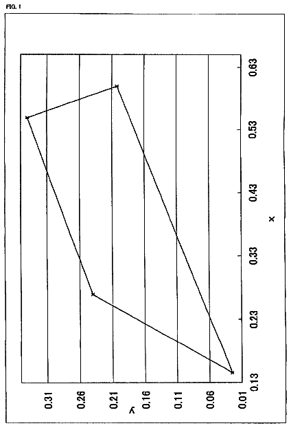
FIG. 1 illustrates an example decoding concept of time-resolved suspension arrays.
FIG. 2 illustrates example methods to encode microsecond-domain time-resolved suspension arrays by lifetime histograms of individual microspheres. In particular (a) a luminescence resonance energy transfer method, (b) an example suspension array assembly by upconversion nanocrystals as building-blocks, (c) an upconversion energy transfer method by adjusting the differential concentration of sensitizer-activators, and (d) a size-dependent luminescence method, by tuning both size and phase of upconversion nanocrystals.
FIG. 3 illustrates an example mapping of individual microspheres, and time-resolved separation of five Red populations carrying coded lifetimes.
FIG. 4 illustrates a three-dimensional time-resolved spectrum for example encoded microspheres after application of UV and IR pulsed excitation beams (a), which can be decomposed into four channels using band-pass colour filters, each channel has its own initial intensity and decay lifetime as two independent parameters (b), leading to a total of eight dimensions as eight digits (c).
FIG. 5 a shows normalized emission spectrum of Eu chelates (under 365 nm), Er and Tm upconversion nanocrystals (under 980 nm).
FIG. 5 b shows spectral overlapping between Er and Tm emission bands when their intensities are at different levels.
FIG. 5 c shows lifetime measured for example microspheres incorporating mixed probes (Eu, Er and Tm), in comparison to microspheres incorporating the same individual probes.
FIG. 6 illustrates example lifetime measurement results from individual Eu-containing microspheres engineered by LRET. Different solutions containing identical amounts of Eu complexes as donor but incremental amount of acceptor dyes were encapsulated into individual groups of polymer microspheres, followed by time-resolved scanning cytometry analysis. (a) Shows the luminescence lifetime measured at Eu.sup.3+ red emission band shortens as the acceptor concentration in the original dye solution increases, as a result of stronger LRET effect. The inset curves are the luminescence decay signals measured from single Eu-LRET microspheres. (b) Shows that among the example samples, five types of example microspheres give completely separate lifetime histograms (as in FIG. 2 a ), so that they are capable of definite discrimination by time-resolved scanning cytometry. The numerals at the left of each histogram are the mean lifetime±the lifetime CV for its Gaussian fitting.
FIG. 7 illustrates an example demonstration of multiplexed DNA detection using lifetime-encoded Eu-LRET example microspheres and time-resolved scanning cytometry. (a) The five selected types of Eu-LRET microspheres (refer to FIG. 6 b ) were conjugated to five different capture probes of DNA sequences (four are complementary to pathogen DNAs from HIV, EV, HBV and HPV-16, and the other is for control purpose). A universal reporter dye was also used in the sandwich beads assay. (b) The example microspheres were identified into different types by measuring their lifetimes from Eu.sup.3+ luminescence decays. (c) The amounts of target pathogen DNAs in the test sample were determined through measuring the fluorescence intensity of the reporter dye. Images were taken with different emission bandpass filters at 500 ms exposure time under continuous excitation. (Scale bar: 10 μm).
FIG. 8 shows a lifetime tuning example method and time-resolved confocal images for NaYF.sub.4:Yb,Tm upconversion nanocrystals. Each pixel was excited for 200 μs followed by a delayed detection window up to 3.8 ms to record its time-gated luminescence decay. The shade or greyscale for each pixel represents its lifetime value decoded from the decay curve. The nanocrystals in the images from left to right have Tm doping concentrations of 4, 2, 1, 0.5 and 0.2 mol %, respectively.
FIG. 9 shows results for example τ-Dots labelled Giardia cysts measured by a time-resolved scanning cytometry system: (a) and (b) show lifetime histograms concluded from cysts labeled with different lifetime-encoded τ-Dots (Tm/Yb codoping concentration (mol %:mol %) of 1:20 for (a) and 4:20 for (b)). The scanning cytometry allows retrieval of each individual target cysts for luminescence as well as bright-field imaging confirmation. (c) shows the typical recorded luminescence images for the same cyst under 4-hour continuous laser excitation.
FIG. 10 shows results for example τ-Dots encoded populations of microspheres as the multiplexing suspension arrays carrying the unique lifetime codes: (a) The synthesized monodispersed Tm upconversion nanocrystals (top TEM image) can be embedded onto the microsphere shell (bottom SEM image). (b) The mechanism of upconversion energy transfer, by adjusting the co-dopant concentration of sensitizer-activator, can generate 8 lifetime populations of microspheres at Tm blue-emission band. The numeral besides each histogram is the mean lifetime±the lifetime CV from Gaussian distribution fitting. The blocks in the axis above represent the lifetime resources (±3σ) occupied by each population, while the open spaces suggest more populations could be engineered. (c) The 2-D (intensity vs. lifetime) scattered plots show all lifetime pollutions independent to intensities of individual micro-carriers.
FIG. 11 shows an example application of lifetime-encoded document security and photonic data storage. Three overlapping patterns are printed with different Tm τ-Dots: (C.sub.Tm:C.sub.Yb) 4:20 for the “Macquarie University” logo; 1:20 for the Opera House image, and 0.5:20 for the Sydney Harbor Bridge image. While intensity-based luminescence imaging only gives a complex difficult to resolve picture (a), in contrast time-resolved scanning separates the patterns based on the lifetimes of every pixel (b), so that the genuine multiplexing information contained in the same overlapping space of document can be decoded (pseudocolour/scale used to map the luminescence lifetime for each pixel in c).
The following modes, given by way of example only, are described in order to provide a more precise understanding of the subject matter of a preferred embodiment or embodiments.
Time-Resolved Scanning: Multiplexed Detection in the Temporal Domain
The Applicant has extended the capability of multiplex assays, for example multiplexing in suspension arrays. This is achieved by utilising or adding a new temporal dimension. In one example, a possible factor of about 100 further codes has been achieved, based upon lifetimes, to the number of codes currently possible in spectral multiplexing, thus bringing the total possible multiplexing level to about 10,000 or more codes. This brings the multiplexing capability in line with the actual level of complexity in biological samples, and also allows a library or database of probes, such as specific microspheres, carrying about 10,000 codes to be built or produced, so as to give users far greater scope and more flexibility with multiplex assay design.
The rationale of the multiplexing strategy is based on the exploration of the temporal domain as an extra dimension in addition to spectrum and intensity. In one example one or more lanthanides were selected as example luminescent probes to produce time-resolved suspension arrays. Lanthanides have an extensive dynamic range associated with their exceptionally-long lifetimes (>100 μs), as well as other attractive properties including narrow emission spectra and large Stokes shift. Example embodiments can use any of the lanthanides, including Lanthanum, Cerium, Praseodymium, Neodymium, Promethium, Samarium, Europium, Gadolinium, Terbium, Dysprosium, Holmium, Erbium, Thulium, Ytterbium, and Lutetium, either individually or in any combination. Other example embodiments can use any of the rare earth elements, which include any of the fifteen lanthanides in addition to Scandium and Yttrium, either individually or in any combination.
The Applicant has identified a number of practical techniques, methods or mechanisms to precisely or accurately tune micro- and/or milli-second luminescent decay rates and produce individual probes and/or microspheres. In one non-limiting example, the probes/microspheres are rare-earth doped probes/microspheres. In another non-limiting example, the probes/microspheres are lanthanide doped probes/microspheres. In another non-limiting example, the probes/microspheres are rare-earth doped polystyrene probes/microspheres.
It will be appreciated that a variety of other types of probes/microspheres are possible, including, for example, nanoparticles assembled to provide microspheres, rare-earth doped silica microspheres, microspheres embedding palladium (Pd) and/or platinum (Pt) phosphorescence, and microspheres embedding charge-transfer (CT) excited transition emitters (such as ruthenium, osmium, and rhenium).
Multiplexed detection of two or more targets, for example five types of example microspheres are discussed, having clearly distinguishable lifetimes, purposely tuned via Luminescence Resonance Energy Transfer (LRET), have been demonstrated and successfully applied to various applications, for example simultaneous probing of different DNA strands.
Luminescent probes showing exceptionally long lifetimes (microseconds to milliseconds) provide advantages over organic fluorophores (of nanoseconds lifetime) in a plurality of fluorescence-based analytical techniques, including background-free biosensing and bioimaging, security application scanning or printing, high-accuracy Energy Transfer measurement, and low-power optical super-resolution imaging. The results allow a new optical library to be built carrying lifetime identifies on top of the overcrowded spectra dimension, in an effort to stimulate new discoveries in life sciences or other areas, such as security inks or dyes, which demand advanced analytical methods.
The decay lifetime of fluorescence, e.g. from organic dyes or quantum dots, is normally in the range up to tens of nanoseconds; however, materials containing certain families of elements, particularly the lanthanide metals or the platinum group metals, usually exhibit extended luminescence decays with lifetimes from microseconds to even milliseconds. Substituting long-lived probes for organic dyes as the donor of resonance energy transfer offers greater accuracy, a larger measurable range and higher labeling tolerance when measuring the distance between donor and accepter from the luminescence lifetime. Long lifetimes can also help lower the power requirement for stimulated emission depletion (STED) super-resolution imaging, for example enabling live monitoring without damaging biological samples or other physical samples such as for security authentication.
Moreover, the lifetime dimension has enormous potential for advanced high-throughput analytical techniques necessitated in modern security applications, microbiology, biochemistry and biomedicine. In a biological application, to simultaneously screen multiple biomolecular species, known as multiplexing, known prevalent techniques rely on a number of different bioprobes fluorescing distinguishable colours, which however blend with one another because their emission spectra typically have spillover issues. This crosstalk problem becomes aggravated as the number of bioprobes increase. For example, current state-of-the-art polychromatic flow cytometry allows measurement up to seventeen fluorescent colours (eleven from organic dyes and six from quantum dots) if only sophisticated colour compensation is provided, not to mention the equipment of four lasers and seventeen individual photodetectors as well as unsustainable cascading of dichroic mirrors and bandpass filters. As alternative approaches, other spectroscopic features, such as mass spectra or Raman spectra using special bioprobes, have been utilized in order to increase the multiplexing capacity. However, these methods are generally incompatible with fluorescence measurement, which otherwise gives an ultimate sensitivity usually two orders of magnitude higher.
In contrast, the Applicant has realized the potential of using lifetime, being a direct parameter associated with fluorescence, so that lifetime can be exploited to generate a new dimension of optical identities, in addition to spectrum and intensity, for multiplexed detection towards high-throughput screening. Particularly, luminescence probes provide a much larger field of play for the lifetime dimension, as well as a background-free advantage, so that control and differentiation of lifetimes provide a practical and accurate alternative compared to conventional known methods.
The discrimination of long luminescence lifetimes is generally beyond the capability of most known commercially available systems. The extraction of lifetime parameters has primarily been carried out in solution/suspension with assistance of post-processing, rather than on individual probes or micro-targets in real-time. This is not only simply owing to the unsuitable excitation/emission wavelength combination for luminescent probes, but also for three more fundamental reasons: 1) the extended luminescence decays may lead to unacceptably long processing time based on prevalent nonlinear fitting algorithms; 2) for cases of rapid lifetime measurement, which relies on low levels of luminescence signal, improper configuration of the detection channels may essentially prevent precise measurement for exceptionally-long lifetimes; 3) the noise of dark current or dark counts, which has been typically ignored for measuring lifetimes in the nanosecond range, have to be taken into account, since the signal profiles associated with long lifetimes incorporate a higher level of noise (proportional to the length of the detection window) that affect the accuracy in the results.
Luminescence Resonance Energy Transfer (LRET) for Tuning Luminescent Decay Rates
A first technique, method or mechanism to precisely or accurately tune micro- and/or milli-second luminescent decay rates is based on Luminescence Resonance Energy Transfer (LRET), in which donors of a lanthanide complex, for example an europium complex, and energy acceptors, such as hexafluorophosphate salt, are in close proximity and interact with one another, and as a result, originally short lifetime acceptor dyes reduce long lifetime luminescence. Varying the donor-to-acceptor distance by changing their respective concentrations makes it possible to fine tune the luminescence lifetimes of both donor and acceptor, which is accompanied by an intensity change.
Referring to FIG. 2 a , there is illustrated an example luminescence resonance energy transfer method or process. By adding incremental amounts of quencher dyes, one can tune rare earth or lanthanide complex lifetimes, for example europium complex lifetimes, to generate an increased number of populations of microspheres, for example 2, 3, 4, 5 or more than 5 populations of microspheres.
In order to introduce fluorophores into microspheres, a method of solvent swelling using an organic solvent is used, allowing the dye molecules to infiltrate the microspheres.
When these microspheres are subsequently transferred into aqueous solution the microspheres shrink and both donor and acceptor dyes become uniformly entrapped. Individual single microspheres were scanned by a prototype time-resolved scanning cytometer where 615 nm (donor europium emission) luminescent lifetimes of single microspheres were plotted into a histogram as shown in FIG. 2 a.
Increasing acceptor concentrations resulted in enhanced LRET efficiency, and accelerated the decay rate of europium donors, consistent with the established formula of LRET. This allows lifetime populations to be coded and decoded.
The lifetime CV was in the range of 1.9% to 5.7%. An alternative method to generate more lifetime populations is through application of a different rare earth complex, for example a different europium complex such as the new europium complex BHHBCB, 1,2-bis[4′-(1″,1″,1″,2″,2″,3″,3″-heptafluoro-4″,6″-hexanedion-6″-yl)benzyl]-4-chlorosulfobenzene, having a much longer luminescence lifetime of 520 μs.
Upconversion Nanocrystals (UPNC) for Tuning Luminescent Decay Rates
A second technique, method or mechanism to precisely or accurately tune micro- and/or milli-second luminescent decay rates is based on rare-earth doped upconversion nanocrystals (UPNC). In this example, a probe or nanocrystal is typically co-doped with thousands of ytterbium (Yb3+) sensitizers and erbium (Er3+) or thulium (Tm3+) emitters, which significantly amplifies the overall intensity per single crystal at tunable size from a few nm to tens of nm. The internal multiphoton sequential energy transfer from the sensitizer (Yb3+) to activator (Er3+) or (Tm3+) can be used to produce individual lifetime-tunable nanocrystals as building blocks to assemble into the lifetime and emission coded probes or microspheres (also referred to as super-beads or mega-beads).
This mechanism was firstly demonstrated by co-doping the Yb to Tm at varied concentrations and ratios in NaYF.sub.4 nanocrystals, which were encapsulated into microspheres by a simple swelling method.
Referring to FIG. 2 b - d , there is illustrated (b) suspension arrays that can be assembled by upconversion nanocrystals as building-blocks; (c) a method of upconversion energy transfer, by adjusting the differential concentration of sensitizer-activators more than 5 populations of Tm microspheres at blue band can be generated; (d) a method of size-dependent luminescence, by tuning both size and phase of upconversion nanocrystals another 4 populations of Er microspheres at green band can be generated. The numerals to the left of each histogram of populations are the mean lifetime±the lifetime CV from Gaussian statistics fitting.
Though the multiphoton energy transfer introduced a nonlinear relationship between the sensitizer-activator distance and luminescence decay rate, interestingly, the Tm variation of 0.5%-4% (Yb fixed at 20%) resulted in a significantly large range of lifetimes from 58.3 μs to 369.6 μs at ˜474 nm, while an increase of Yb concentration from 10% to 30% (Tm fixed at 1%) also significantly accelerated the blue emission decay from 206.7 μs to 115.4 μs. These results were obtained with a time-resolved upconversion scanning cytometer.
This clearly realized another five completely separated lifetime channels at the blue band. The demonstrated lifetime CV dynamic range was from as low as 5% up to 8%. The narrow CV and continuous tunable lifetime range by either Yb or Tm variation could easily support up to seven lifetime channels.
Size and Phase of Upconversion Nanocrystals (UPNC) for Tuning Luminescent Decay Rates
A third technique, method or mechanism to precisely or accurately tune micro- and/or milli-second luminescent decay rates is based on the lifetime-tunable feature of different size and phase of upconversion nanocrystals, such as NaYF4:Yb, Er. When Yb and Er doping concentrations were fixed at 20% and 2% respectively, cubic phase crystals typically yield shorter lifetime than hexagonal phase crystals due to an increased level of crystal defects and internal quenching, and smaller-sized crystals emit shorter lifetime luminescence due to higher surface quenching by large surface-to-volume ratio.
In a particular example, by encapsulating 6 nm (cubic), 15 nm (cubic), 30 nm (hexagonal) and 40 nm (hexagonal) nanocrystals into microspheres, four clearly separated lifetime channels were created in a green band, with statistical lifetime histograms plotted in FIG. 2 d . For example, microspheres prepared by advanced nanocrystal self-assembly techniques achieved a green luminescence lifetime of about 200 μs. Thus, it is possible to create about five or more lifetime channels in the green band, for example between about 33 μs (for 6 nm, cubic) to about 200 μs. Alternatively different nanocrystal host materials, such as Y.sub.2O.sub.3 nanocrystals, having slightly higher phonon energies, can quench the luminescence decay rate.
Referring now to FIG. 3 , there is illustrated mapping of example individual microspheres, and time-resolved separation of five Red populations carrying coded lifetimes. The gray scale bar represents the lifetime values. When mixing different lifetime populations of microspheres, the decoding system can accurately separate them into their original lifetime groups. This shows no crosstalk between neighborhood lifetime populations.
To further evaluate time-resolved suspension arrays, the five families of europium LRET microspheres were mixed together and deposited onto a glass slide. An area of 15×15 mm.sup.2 of the sample was analyzed using a time-resolved scanning cytometer. After 3 minutes rapid scanning, the positions of the mixed microspheres where localized on x-y coordinates as shown in FIG. 3 a , and the variant lifetimes of single microspheres were then decoded as gray intensity tones. From the lifetime histogram (see FIG. 3 b ), the same boundaries in FIG. 2 b can be clearly recovered to distribute the mixed sample into the original five sub-populations (see FIG. 3 c ). This approach indicates that the multiplex assay technique using suspension arrays provides a randomly distributed solid-phase analog of the planar array multiplexing method. This example shows results for a multiplexing detection process for lifetime-encoded Eu-LRET example microspheres, using time-resolved scanning cytometry. FIG. 3 a shows an example mapping result (in this example locations on a microscopic slide) of a mixture of five selected types of Eu-LRET microspheres. The tones bar represents the lifetime values. FIG. 3 b shows individual types of microspheres in the mixed sample are recognized based on the separation of lifetime populations using definite boundaries in between. FIG. 3 c shows the initial mapping result for the mixed sample is thus decomposed into five planes of different lifetime regions for individual types of Eu-LRET microspheres carrying lifetime identities.
In one particular example, polymer microspheres were doped with four types of lanthanide probes at respective concentrations: two are down-conversion luminescence materials: Eu chelates or Eu nanocrystals emitting red luminescence (615 nm), Tb complexes or Tb nanocrystals, both of which only emit luminescence under UV (<400 nm) excitation, and two are upconversion luminescence materials: Tm UPNCs emitting blue luminescence (475 nm), and Er UPNCs emitting green luminescence (545 nm), both of which only emit luminescence by IR illumination. Moreover, their radiative decay profiles are delicately engineered, resulting in distinct lifetimes for each emission wavelength.
The description continues in the full USPTO document.
About 5,516 words. The USPTO PDF has it with every drawing.
Fees are due 3.5, 7.5 and 11.5 years after grant. This patent expired on November 14, 2025, so the fee marked "not paid" was the one that went unpaid.
MULTIPLEX SUSPENSION ASSAY/ARRAY USING LIFETIME CODING
Filed Jun 2013 · published Jul 2015Multiplex suspension assay/array using lifetime coding
Filed Jun 2013 · granted Nov 2017Earlier publications, parents and continuations. None of them can still be enforced, or this patent would not be listed.
Prior art cited by the examiner or applicant. Useful when you check your own idea for novelty.
Everything on this page comes from the documents linked above.