Related u.s.
Applications
Not applicable.
Statement regarding federally sponsored research or development
Not applicable.
Reference to microfiche appendix
Not applicable.
Background of the invention
1. Field of the invention
The present invention relates to a drive motor, more particularly to a master-slave flywheel drive motor.
2. Description of related art
Including Information Disclosed Under 37 CFR 1.97 and 37 CFR 1.98
Currently most of pure electric vehicle drive motors use variable speed mechanical design, mechanical transmission and gearbox is big and heavy, low mechanical efficiency and large loss.
Summary of the invention
Technical problems to be solved by the present invention is to provide a master-slave flywheel drive motor to address the problem of current drive motor and gearbox in big and heavy, low mechanical efficiency and large loss.
The present invention solves the above technical problems the technical solution as follows: a master-slave flywheel drive motor, including a shaft, master motor, master flywheel, slave motor bracket, outer rotor of slave motor and drive connector, slave motor coil winding and magnet wheel. The master motor, master flywheel, slave motor bracket, outer rotor of slave motor and drive connector are sequentially fitted over the shaft, slave motor coil winding and magnet wheel are sequentially fitted over the outside of the master motor.
Furthermore, there is a slave motor three-phase electrode fixed boss on the master flywheel, the three-phase electrode fixed boss integrally formed with the master flywheel.
Furthermore, the drive motor includes slave motor three-phase electrodes and stator, the slave motor stator is fitted over the slave motor bracket, the slave motor three-phase electrodes are fitted over the fixed boss.
Furthermore, the three-phase electrodes number is 3.
Furthermore, there is heat dissipation structure on the master motor.
The beneficial effects of the present invention are: the drive motor without shifting mechanism can achieve the CVT function by regulating the motor current, and recover a part of the power. While the use of the drive motor inertia from flywheel supplements vehicle's requirement of high current supply for frequent start-up, that can reduce the current demand on the battery and minimize the risk of the large current damaging the electronic control system. Using the inertia of flywheel also reduce the battery power consumption to improve system security and reliability of vehicle, extending its life and achieve electromagnetic energy efficient CVT.
Brief description of the drawings
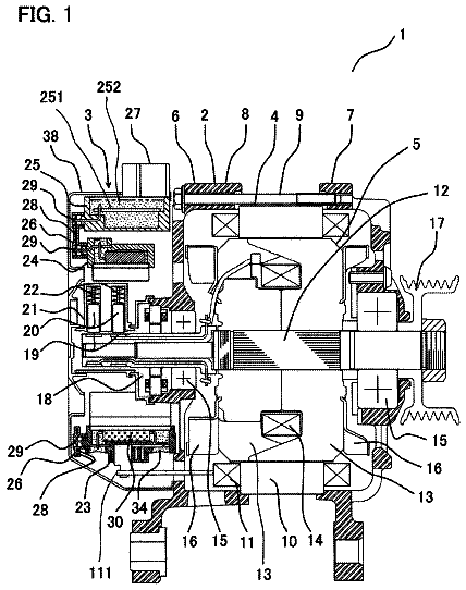
The FIGURE is a schematic view of an embodiment of the present invention.
Each numeral list parts represented as follows: 1 , Shaft, 2 , Master motor, 3 , Master flywheel, 4 , Slave motor bracket, 5 , Outer rotor of slave motor and drive connector, 6 , Slave motor coil winding, 7 , Magnet wheel, 8 , Slave motor three-phase electrodes, 9 , Slave motor stator, 10 , Slave motor three-phase electrode fixed boss, 11 , Heat dissipation structure invention.
Detailed description of the drawings
The principles and features of the present invention will be described, the examples only serve to illustrate the invention and are not intended to limit the scope of the invention.
A master-slave flywheel drive motor is shown in FIG. 1 , includes shaft 1 , master motor 2 , master flywheel 3 , slave motor bracket 4 , outer rotor of slave motor and drive connector 5 , slave motor coil winding 6 and magnet wheel 7 . The master motor 2 , master flywheel 3 , slave motor bracket 4 and outer rotor of slave motor and drive connector 5 are sequentially fitted over the shaft 1 . The slave motor coil winding 6 and magnet wheel 7 are sequentially fitted over the outside of master motor 2 .
The master flywheel 3 with slave motor three-phase electrode fixed boss 10 on the side, the three-phase electrode fixed boss 10 integrally formed with the master flywheel 3 .
The drive motor includes slave motor three-phase electrodes 8 and stator 9 , the slave motor stator 9 is fitted over the slave motor bracket 4 , the slave motor three-phase electrodes 8 are fitted over the fixed boss 10 .
The three-phase electrodes 8 number is 3.
There is heat dissipation structure 11 on the master motor 2 .
The above description presents a preferred embodiment of the present invention, which is not intended to limit the present invention, any modification within the spirit and principles of the present invention, equivalent replacement, improvement, etc., should be included in the protection range of the present invention.
 Lapsed, fee not paid4 drawings