Field of the invention and related art
The present invention relates to an image heating apparatus for heating a toner image on a sheet. This image heating apparatus is mountable in an image forming apparatus, of an electrophotographic type, such as a copying machine, a printer, a facsimile machine or a multi-function machine of these machines.
In recent years, a fixing device (image heating apparatus) of a belt heating type has been put into practical use from the viewpoints of a quick start property and an energy saving property. Specifically, a fixing belt (endless belt) is sandwiched between a ceramic heater and a pressing roller, so that a nip is formed. Into the nip, a recording material (sheet) on which a toner image is formed is introduced and then heated and pressed, so that the toner image is fixed on the recording material.
Thus, the fixing device of the belt heating type is a thin fixing belt and is small in thermal capacity, and also has a good thermal responsivity, and therefore thermal response of the heater can be efficiently reflected in the fixing belt. Further, a temperature of the fixing belt can be caused to reach a target fixing temperature in a short time from turning-on of the heater, and on the basis of these effects, electric power saving is realized.
In such a fixing device, if in the case where a stapled recording material is introduced into a nip, there is a liability that a crack occurs at a widthwise end portion of the fixing belt. Such a crack becomes large with continuous image formation and finally causes an image defect.
In a fixing device disclosed in Japanese Laid-Open Patent Application (JP-A) 2014-10319, a method in which two thermistors for detecting a temperature of a fixing belt at a widthwise central portion and a width one end portion are provided for detecting abnormal rotation of the fixing belt has been proposed although the method does not aim at detection of the crack. Specifically, in JP-A 2014-10319, a technique for discriminating whether or not the fixing belt is rotated depending on a difference in detection temperature between the two thermistors is disclosed.
However, in the case where the method disclosed in JP-A 2014-10319 is used, the following problem cannot be solved.
FIG. 6 shows the case where a crack K occurs in the neighborhood of a widthwise end portion of a fixing belt. Here, the crack K has a length (width) W with respect to a widthwise direction of the fixing belt and has a length (width) L with respect to a circumferential direction of the fixing belt. Further, the fixing belt is 30 mm in diameter.
According to study by the present inventor, in the above method, an occurrence of the crack K could not be detected from an occurrence of a crack K of W=1 mm and L=1 mm until a size of the crack K grows to W=15 mm and L=45 mm with continuous image formation.
Such a crack may preferably be detected early, and therefore a method for that purpose has been required.
Summary of the invention
According to an aspect of the present invention, there is provided an image heating apparatus comprising: an endless belt configured to heat a toner image on a sheet; a temperature raising portion configured to raise a temperature of the endless belt; a first detecting portion configured to detect the temperature of the endless belt at a widthwise central portion of the endless belt; a controller configured to control energization to the temperature raising portion depending on an output of the first detecting portion; a second detecting portion configured to detect the temperature of the endless belt at a widthwise one end portion of the endless belt; an air blowing portion configured to blow air depending on an output of the second detecting portion to cool the widthwise one end portion of the endless belt; and a discriminating portion configured to discriminate whether or not the endless belt is broken on the basis of the output of the second detecting portion when the air blowing portion is operated while effecting the energization to the temperature raising portion.
Further features of the present invention will become apparent from the following description of exemplary embodiments with reference to the attached drawings.
Brief description of the drawings
FIG. 1 is a schematic longitudinal sectional front view of a principal part of a fixing device in Embodiment 1.
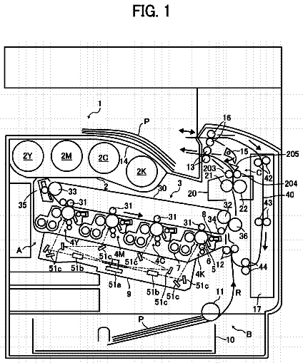
FIG. 2 is a schematic view of an example of an image forming apparatus.
FIG. 3 is an enlarged cross-sectional right side view of the principal part of the fixing device shown in FIG. 1 .
FIG. 4 is an exploded perspective view of a belt unit in a left side (one end side).
FIG. 5 is an exploded perspective view of the belt unit in a right side (the other end side).
FIG. 6 is an illustration of a crack.
FIG. 7 is a flowchart of an operation in a control mode.
FIG. 8 is a schematic view of abnormal notification on a display panel.
FIG. 9 is a graph showing a detection temperature of a thermistor.
FIG. 10 is a flowchart of an operation in a control mode in Embodiment 2.
FIG. 11 is a graph showing a detection temperature of a thermistor.
FIG. 12 is a flowchart of an operation in a control mode in Embodiment 3.
FIG. 13 is a schematic longitudinal sectional front view of a principal part of a fixing device in Embodiment 4.
Description of the embodiments
[Embodiment 1]
Image Forming Apparatus
FIG. 2 is a schematic view of an example of an image forming apparatus 1 in which an image heating apparatus according to the present invention is mounted as a fixing device (fixing apparatus) 40 . This image forming apparatus 1 is a four-color basis full-color electrophotographic laser printer of an intermediary transfer type and a tandem type, and is capable of forming and printing out a full-color toner image on a sheet P. The sheet P is a recording material (recording medium) on which the toner image is capable of being formed, and may comprise plain paper, glossy paper, a resin-made sheet, thick paper, a postcard, an envelope, an OHP sheet, printing paper, format paper or the like. Hereinafter, these sheets or papers are referred to as the sheet P. Printer constitutions other than the constitution of the fixing device 40 are well known, and therefore will be briefly described below.
An image forming portion 2 includes process cartridges 3 (3Y, 3M, 3C, 3K) as 4 image forming units which are juxtaposed, a laser scanner unit 4 as an exposure means, and an intermediary transfer belt unit 5 . Each cartridge 3 includes a rotatable drum-type photosensitive member 6 , a charging roller 7 , a developing device 8 , a primary transfer roller 9 , a cleaning member 10 , and the like which are used as electrophotographic image forming process means. Each cartridge 3 forms a toner image (developer image) of yellow (Y), magenta (M), cyan (C) or black (K) on the associated photosensitive member 6 .
The above 4 color toner images are successively primary transferred from the photosensitive members of the cartridges 3 onto an intermediary transfer belt 11 in a predetermined superposition manner, so that a full-color toner image is formed on the intermediary transfer belt 11 . Then, the full-color toner image is secondary-transferred onto the sheet P at a secondary transfer nip 16 which is a press-contact portion between the intermediary transfer belt 11 and a secondary transfer roller 15 .
The sheet P is separated and fed one by one from a sheet cassette 12 and is introduced into the secondary transfer nip 16 at predetermined control timing along a feeding path 14 including a registration roller pair 13 . Then, the sheet P subjected to secondary transfer of the toner image is introduced into the fixing device 40 , so that the toner image is fixed on the sheet P under application of heat and pressure.
The sheet P coming out of the fixing device 40 is discharged as a full-color image-formed product by a discharging roller pair 17 onto a tray 18 which is an upper surface of the image forming apparatus. In the case of an operation in a monochromatic image forming mode, only the cartridge necessary to form an associated color toner image performs an image forming operation, and other cartridges are only subjected to idling of the photosensitive members 6 but do not perform the image forming operation.
In the image forming apparatus 1 in this embodiment, feeding of the sheet P in the apparatus is made by a so-called center(-line) basis feeding. This sheet feeding is made so that even any width sheet usable (passable) in the apparatus is passed in such a manner that a widthwise center line of the sheet is aligned with a widthwise center of a sheet feeding path.
Fixing Device
The fixing device 40 in this embodiment is an image heating apparatus of a belt (film) heating type and a pressing roller driving type (tension-less type). FIG. 1 is a schematic longitudinal sectional front view of a principal part of the fixing device 40 , and FIG. 3 is an enlarged cross-sectional right side view of the principal part of the fixing device 40 .
In this embodiment, with respect to the fixing device 40 or constituent members thereof, a front (surface) side is a side (surface) in which the device or member is viewed from a sheet entrance side, and a rear (surface) side is a side (surface) (sheet exit side) opposite from the front side. Left and right are left (one end side) and right (the other end side). Upper (above) and lower (below) are those with respect to the direction of gravity. A longitudinal direction (or widthwise direction) or a sheet width direction is a direction substantially parallel to a direction perpendicular to a sheet feeding direction a in a sheet feeding path plane. A short direction is a direction substantially parallel to the sheet feeding direction a in the sheet feeding path plane.
In this embodiment, the fixing device 40 is provided so that the front side which is the sheet entrance side is directed downward relative to an image forming apparatus main assembly, so that the sheet P fed upward from the secondary transfer nip 16 is guided by a sheet back surface guiding member (not shown) to be introduced into the fixing device 40 from below to above.
The fixing device 40 includes a belt unit 111 provided with a cylindrical fixing belt (heat-conductive member) 101 as a rotatable endless belt for heating the image on the sheet (recording material) at the nip. The fixing device 40 further includes a pressing roller (pressing member) 106 as a nip-forming member for forming the nip between itself and the fixing belt 101 and for nip-feeding the sheet P on which the toner image T is carried. The fixing device 40 further includes a fixing frame (casing) 112 in which the belt unit 111 and the pressing roller 106 are accommodated.
The fixing device 40 further includes, for taking countermeasures against end portion temperature rise, an abnormal cooling unit 120 as an air blowing portion for cooling the belt 101 in each of one end side and the other end side with respect to the widthwise direction (longitudinal direction) from an outside of the belt.
(2-1) Belt Unit
FIG. 4 is an exploded perspective view of the belt unit 111 in a left side (one end side), and FIG. 5 is an exploded perspective view of the belt unit 111 in a right side (the other end side).
The belt unit 111 includes the cylindrical fixing belt 101 . The belt unit 111 further includes a ceramic heater (heating member, heat generating source) 100 , a back-up member (press-contact member) 103 , a stay (reinforcing member) 102 and 3 (central portion, left side, right side) thermistors (detecting portions) 105 C, 105 F, 105 R, which are provided inside the fixing belt (endless belt) 101 . The belt unit 111 further includes left and right fixing flanges 104 F, 104 R. Each of the fixing belt 101 , the ceramic heater 100 , the back-up member 103 and the stay 103 is a long member extending in a left-right direction.
The fixing belt 101 is a heat-resistant member which functions as a heat-conductive member for conducting heat to the sheet P and which has a small thickness and flexibility. In order to improve a quick start property by decreasing a thermal capacity, as the fixing belt 101 , it is possible to use a single-layer belt formed of PTFE, PFA, FEP or the like in a thickness of 100 μm or less, preferably 50 μm or less and 20 μm or more, for example. Further, it is also possible to use a composite-layer belt prepared by coating PTFE, PFA, FEP or the like on an outer peripheral surface of a layer of polyimide, polyamideimide, PEEK, PES, PPS or the like. Further, it is also possible to use a belt formed of metal.
In this embodiment, the fixing belt 101 which was prepared by forming an elastic layer on a cylindrical thin metal base layer and which had flexibility was used. In a free state, the fixing belt 101 assumed a substantially cylindrical shape by its own elasticity.
The ceramic heater (temperature raising portion) 100 has a basic constitution including an elongated thin plate-like ceramic substrate and an energization heat-generating resistor layer formed on a surface of the substrate and is a low-thermal capacity heater (heating portion) increasing in temperature with an abrupt rising characteristic in an entire effective heat-generating length region by energization to the heat-generating resistor layer. The heater 100 is engaged in and supported by a heater engaging groove portion 103 a formed along a longitudinal direction of the back-up member 103 in an outer surface side of the back-up member 103 .
The back-up member 103 is a molded member which has a substantially semi-circular cross-section and which is formed of a heat-resistant and heat-insulating material, and another surface thereof supporting the heater 100 slides with an inner peripheral surface of the fixing belt 101 . The back-up member 103 is formed of a material having good insulating and heat-resistant properties, such as phenolic resin, polyimide resin, polyamide resin, polyamideimide resin, PEEK resin, PES resin, PPS resin, PFA resin, PTFE resins, or LCP resin.
The back-up member 103 not only holds the heater 100 but also has the function of realizing pressure application at the nip formed by the back-up member 103 press-contacted to the pressing roller 106 and feeding stability during rotation of the fixing belt 101 .
The stay 102 is a rigid member for not only providing the back-up member with a longitudinal strength but also rectifying the back-up member by being pressed against an inner surface of a relatively soft back-up member formed of the resin material. In this embodiment, the stay 102 is formed of a metal molding material such as iron or aluminum having a U-shape in cross-section.
The fixing belt 101 is loosely fitted around an assembly of the back-up member 103 and the stay 102 . Left side end portions (one end side end portions) 103 b F, 102 a F and right side end portions (the other end side end portions) 103 b R, 102 a R of the back-up member 103 and the stay 102 are extended and projected from left and right end portions toward outsides of the fixing belt 101 , respectively.
The heater 100 has a length substantially corresponding to a full length portion of the back-up member 103 including the left and right extended end portions 103 b F, 103 b R. On each of heater substrate end portion surfaces corresponding to the left and right extended end portions 103 b F, 103 b R of the back-up member 103 , an electrode portion for energization (not shown) exists.
The left and right fixing flanges 104 F, 104 R are engaged with the left and right extended end portions 102 a F, 102 a R of the stay 102 projected from the left and right end portions toward the outsides of the fixing belt 101 . In this embodiment, the left and right extended end portions 102 a F, 102 a R of the stay 102 are engaged in holes 104 b formed in the left and right fixing flanges 104 F, 104 R. As a result, the left and right fixing flanges 104 F, 104 R are engaged with the left and right extended end portions 102 a F, 102 a R of the stay 102 , respectively.
Each of the left and right fixing flanges 104 F, 104 R includes a flange seat 104 a for regulating (limiting) the end portion of the fixing belt 101 and an arcuate guiding portion 104 c for guiding the inner peripheral surface of the end portion of the fixing belt 101 . In a side opposite from the guiding portion 104 c side of the flange seal 104 a , a pressure-receiving portion 104 d is provided. In a state in which the left and right fixing flanges 104 F, 104 R are engaged with the left and right extended end portions 102 a F, 102 a R of the stay 102 , respectively, the guiding portions 104 c are engaged into the left and right end portions of the fixing belt 101 .
The 3 (central portion, left side, right side) thermistors 105 C, 105 F, 105 R are temperature detecting members for detecting temperatures of the fixing belt 101 at a longitudinal central portion (widthwise central portion), a left side end portion (one end side) and a right side end portion (the other end side), respectively, in the inside of the fixing belt 101 . The thermistors 105 C, 105 F, 105 R are mounted inside the back-up member 103 at free end portions of leaf spring portions 105 b fixedly mounted at their base portions on pedestals 105 a provided at the longitudinal central portion, the left side end portion and the right side end portion, respectively.
The stay 102 is provided with holes (through holes) 102 b at predetermined locations corresponding to the respective pedestals 105 a in the back-up member 103 side. Each of the leaf spring portions 105 b is projected toward the outside of the stay 102 through the associated hole 102 b . Each of the thermistors 105 C, 105 F, 105 R at the leaf spring free end portion is urged against the inner surface of the fixing belt 101 at a predetermined contact pressure by elasticity of the leaf spring portion 105 b , thus detecting an inner surface temperature of the fixing belt 101 . In this embodiment, the leaf spring portion 105 b is formed of stainless steel and also constitutes an electrical conduction path for the associated thermistor
(2-2) Pressing roller
The pressing roller (rotatable driving member) 106 is constituted by a core metal 106 a and a heat-resistant elastic layer 106 b which is formed by molding in a roller shape coaxially with an axis of the core metal and which is coated on the core metal 106 b with silicone rubber, fluorine-containing rubber, fluorine-containing resin, or the like. On the elastic layer 106 b , a parting layer 106 c is formed as a surface layer. As a material for the parting layer 106 c , it is possible to select a material having good parting and heat-resistant properties, such as fluorine-containing resin, silicone resin, fluorosilicone rubber, fluorine-containing rubber, PFA, PTFE, FEP, or the like, for example.
The pressing roller 106 is provided so that left and right shaft portions 106 d thereof are rotatably held between left and right side plates 112 F, 112 R of the fixing frame 112 via bearing members 113 formed of a heat-resistant resin material such as PEEK, PPS, a liquid crystal polymer or the like. At an end portion of the right side shaft portion 106 d , a driving gear G is provided substantially concentrically integral with the shaft portion 106 d . To the pressing roller 106 , a driving force of a first motor M 1 controlled by a controller 200 is transmitted via a drive transmitting mechanism (not shown). As a result, the pressing roller 106 is rotationally driven as the rotatable driving member at a predetermined peripheral speed in the clockwise direction indicated by an arrow R 106 in FIG. 3 .
The left and right side plates 112 F, 112 R of the fixing frame 112 are provided with slit portions 112 a , in a mirror symmetrical manner, into which base portions of the pressure-receiving portions 105 d of the left and right fixing flanges 104 F, 104 R. The slit portions 112 a are guiding portions for slidably (movably) holding the pressure-receiving portions 104 d of the fixing flanges 104 F, 104 R in directions in which the portions 104 d move toward and away from the pressing roller 106 .
In the belt unit 111 , the heater 100 is disposed opposed to the pressing roller 106 substantially parallel to the pressing roller 106 , and the pressure-receiving portions 105 d of the left and right fixing flanges 104 F, 104 R are engaged in the slit portions 112 a . Thus, to the pressure-receiving portions 104 d of the left and right fixing flanges 104 F, 104 R, a predetermined pressure is applied by pressing mechanisms 109 F, 109 R, respectively.
Although a specific structure of each of the pressing mechanisms 109 F, 109 R is omitted from the figures, for example, an appropriate pressing mechanism such as a pressing mechanism including a pressing spring and a pressing plate, a pressing mechanism including a pressing cam or a pressing mechanism using an electromagnetic solenoid can be used. Further, it is also possible to use a mechanism capable of eliminating the pressure as desired.
By the pressure of the pressing mechanisms 109 F, 109 R, the stay 102 , the back-up member 103 , the heater 100 and the fixing belt 101 are press-contacted to the pressing roller 106 against the elasticity of the elastic layer 106 b . As a result, between the fixing belt 101 and the pressing roller 106 , the nip having a predetermined width with respect to the short direction is formed.
Electrical connectors 107 F, 107 R are inserted into the fixing flanges 104 F, 104 R through holes 104 e provided in the pressure-receiving portions 104 d of the fixing flanges 104 F, 104 R and are engaged with the left and right extended end portions 103 b F, 103 b R of the back-up member 103 supporting the heater 100 . As a result, the heater 100 and a power source portion (energizing portion) 201 are electrically connected with each other, so that energization from the power source portion 201 to the heater 100 can be made.
Further, in this embodiment, also such a constitution that pieces of electrical information on detection temperatures of the thermistors 105 C, 105 F, 105 R is fed back to the controller 200 via these electrical connectors 107 F, 107 R is employed.
(2-3) Air Blowing Cooling Unit
An air blowing cooling unit 120 as an air blowing portion is a mechanism portion for alleviating a degree of temperature rise by air blowing cooling at non-sheet passing portion (non-recording material passing portion) (i.e., end portion temperature rise) in each of one end side and the other end side of the fixing belt 101 with respect to the widthwise direction when a small-sized sheet having a width smaller than a width of a maximum width sheet usable in the apparatus is introduced in the fixing device.
The air blowing cooling unit 120 in this embodiment is provided in a side opposite from the pressing roller 106 side of the belt unit 111 . The air blowing cooling unit 120 includes a unit substrate 121 mounted between the left and right side plates 112 F, 112 R of the fixing frame 112 . The unit substrate 121 is provided with air blowing openings 122 F, 122 R in left and right end portion sides, respectively. The unit substrate 121 is further provided with shutter plates 61 F, 61 R for adjusting an opening width of the air blowing opening 122 F, 122 R by movement in the widthwise direction (longitudinal direction) of the fixing belt 101 .
Although details of moving mechanisms for the shutter plates 61 F, 61 R are omitted from the figures, in this embodiment, a stepping motor (second motor) M 2 controlled by the controller 200 so as to be driven in normal and reverse directions and a reciprocating portion which is driven by the motor M 2 and which includes a pinion gear and a rack are provided. The shutter plates 61 F, 61 R are moved symmetrically in synchronism with each other by an operation of the reciprocating portion in a direction (opening direction) in which the opening widths of the air blowing openings 122 F, 122 R are broadened or a direction (closing direction) in which the opening widths of the air blowing openings 122 F, 122 R are narrowed with respect to the widthwise direction of the fixing belt 101 as indicated by arrows in FIG. 1 .
Outside the unit substrate 122 , fans (end portion cooling fans) 60 F, 60 R for blowing air toward the air blowing openings 122 F, 122 R are provided. The fans 60 F, 60 R are ON/OFF-controlled by the controller 200 .
In FIG. 1 , Wmin is a sheet passing portion width (sheet passing region width) of a minimum width sheet usable in the apparatus, and Wmax is a sheet passing portion width of a maximum width sheet usable in the apparatus. In this embodiment, feeding of the sheet P in the apparatus is made by the so-called center(-line) basis feeding. The minimum width (Wmin) sheet P is an A5R (148 mm×210 mm: short edge feeding) sheet, and the maximum width (Wmax) sheet P is an SRA (320 mm×450 mm: long edge feeding) sheet. Each of the opening widths of the air blowing openings 122 F, 122 R is set at a width corresponding to a non-sheet passing portion width when the minimum width sheet is passed through the fixing device 40 .
Movement amount control of the shutter plates 61 F, 61 R is effected so that the opening widths of the air blowing openings 122 F, 122 R are adjusted to opening widths corresponding to non-sheet passing portion widths generated by the width of the associated one of sheets having various sizes from A5R to SRA.
Here, as a temperature detecting member for thermistor control of the heater 100 , the central portion thermistor 105 C detects the inner surface temperature of the fixing belt 101 in a region corresponding to passing region of the minimum width (Wmin) sheet. In this embodiment, the central portion thermistor 105 C is disposed so as to detect the temperature of the fixing belt 101 at a portion corresponding to a substantially central portion with respect to the longitudinal direction (widthwise direction). Each of the left and right thermistors 105 F, 105 R is disposed as a temperature detecting member for detecting end portion temperature rise so as to detect the inner surface temperature of the associated fixing belt end portion corresponding to a region somewhat inside a region end line of the sheet passing region of the maximum width (Wmax) sheet.
That is, the left and right thermistors 105 F, 105 R are disposed so as to detect the temperatures of the fixing belt 101 in one end side and the other end side, respectively, with respect to the widthwise direction of the fixing belt in the inside of the fixing belt 101 .
(2-4) Fixing operation
The controller 200 (also functioning as a discriminating portion) starts rotational drive of the pressing roller 106 on the basis of an image formation start signal (job execution signal) by actuating the first motor M1. By a frictional force generated at the nip N between the pressing roller 106 and the outer surface of the fixing belt 101 by the rotational drive of the pressing roller 106 , a rotational force (rotational torque) acts on the fixing belt 101 . As a result, the fixing belt 101 is rotated by the rotational drive of the pressing roller 106 at a peripheral speed substantially corresponding to the rotational peripheral speed of the pressing roller 106 in the counterclockwise direction indicated by an arrow R101, while the inner surface thereof slides with and is in intimate contact with the outer surface of the back-up member 103 , including the heater 100 , at the nip N.
In order to smooth the rotation of the fixing belt 101 by the pressing roller 106 , it is preferable that a lubricant (not shown) is interposed at (applied onto) a mutual sliding portion between the fixing belt 101 and the outer surface of the back-up member 103 including the heater 100 .
The controller 200 causes the power source portion 201 to supply electric power to the heater 100 . As a result, the heater 100 abruptly increases in temperature, so that the fixing belt 101 rotating while sliding with the heater 100 at the inner peripheral surface thereof is heated. On the basis of detection information of the fixing belt temperature fed back from the central portion thermistor 105 C, the controller 200 raises the fixing belt temperature to a predetermined fixing temperature. Then, the controller 200 controls electric power supplied to the heater 100 so that the fixing temperature is maintained, so that the temperature of the fixing belt 101 is controlled.
In this state of the fixing device 40 , the sheet P on which the (unfixed) toner image T is carried is introduced from the secondary transfer portion 16 of the image forming portion 2 , and is nip-fed through the nip N. As a result, the toner image T and the sheet P are heated and pressed by heat of the fixing belt 101 and the nip pressure, so that the toner image T is fixed as a fixed image on the sheet P. The sheet P nip-fed through the nip N is curvature-separated from the surface of the fixing belt 101 at a sheet exit of the nip N and then is discriminated and fed from the fixing device 40 .
The air blowing cooling unit 120 is controlled in the following manner. When a job for continuously passing (introducing) small-sized sheets, having a width smaller than the width of the maximum width sheet usable in the apparatus, through the nip N is executed, end portion temperature rise (non-sheet passing portion temperature rise) in which the temperature of the fixing belt 101 at the non-sheet passing portion (non-recording material passing portion) becomes higher than the temperature of the fixing belt 101 at the sheet passing portion (recording material passing portion) occurs. The increased temperatures at left and right end portions of the fixing belt 101 are detected by the left and right thermistors 105 F, 105 R, respectively.
On the basis of pieces of temperature information fed back from the end portion thermistors 105 F, 105 R, when it is confirmed that the end portion temperatures reach a first set temperature (upper limit allowable temperature of the end portion temperature rise), the controller 200 turns on the fans 60 F, 60 R. In this embodiment, the first set temperature is 220° C.
Then, the controller 200 moves the shutter plates 61 F, 61 R so that the opening widths of the air blowing openings 122 F, 122 R become opening widths corresponding to the non-sheet passing portion widths formed by the small-sized sheet passed through the fixing device 40 . The movement control of the shutter plates 61 F, 61 R may also be executed before the start of the job on the basis of width size information of a using sheet inputted into the controller 200 at the time of start of the image formation.
By the above-described turning-on of the fans 60 F, 60 R and movement control of the shutter plates 61 F, 61 R, air blowing cooling (end portion cooling) of the fixing belt 101 in the non-sheet passing region depending on the width size of the using sheet is made, so that the end portion temperatures of the fixing belt 101 are lowered. That is, the air blowing cooling unit 120 cools the fixing belt 101 by blowing air toward the fixing belt 101 in arrow d directions in FIG. 1 in the non-sheet passing region.
When it is confirmed by the end portion thermistors 105 F, 105 R that the end portion temperatures are lowered by the above air blowing cooling to a predetermined second set temperature, i.e., 170° C. in this embodiment, lower than the first set image, the controller 200 turns off the fans 60 F, 60 R. That is, the end portion cooling of the fixing belt 101 is stopped.
As described above, during the continuous sheet passing job of the small-sized sheets, when the end portion thermistors 105 F, 105 R confirm that the fixing belt end portion temperatures increase up to the predetermined first set temperature, the controller 200 turns on the fans 60 F, 60 R to start the air blowing cooling. Then, when the end portion thermistors 105 F, 105 R confirm that the fixing belt end portion temperatures decrease down to the predetermined second set temperature, the controller 200 turns off the fans 60 F, 60 R to stop the air blowing cooling. Then, by repeating the start and the stop of the above-described air blowing cooling until the job ends, a degree of the end portion temperature rise is alleviated.
In the case where the passed sheet is the maximum width sheet usable in the fixing device 40 , even when the job is the continuous sheet passing job, the temperature of the fixing belt 101 is controlled substantially over a full width to the predetermined fixing temperature on the basis of the detection information fed back from the central portion thermistor 105 C. For that reason, the end portion temperature rise does not generate and the turning-off state of the fans 60 F, 60 R is maintained, so that the end portion cooling of the fixing belt 101 is not performed.
Abnormal Detection of Fixing Belt
A detecting method in the case where the fixing belt 101 caused abnormality, i.e., crack (breakage) will be described. In this embodiment, in the following case, the controller (discriminating portion) 200 discriminates that the breakage of the fixing belt 101 occurred. That is, in the case where a difference in detection temperature between the left and right thermistors 105 F, 105 R is a predetermined temperature difference in a state in which the air blowing cooling unit 120 is actuated due to the end portion temperature rise caused by continuously passing the small-sized sheets through the fixing device 40 , the controller 200 is notified of an abnormality of the fixing belt 101 .
This will be described using the case where the crack (breakage) K occurs only at the left side (F side) end portion of the fixing belt 101 as shown in FIG. 6 . In FIG. 6 , a crack length of the fixing belt 101 with respect to the longitudinal direction (widthwise direction) is W, and a crack length of the fixing belt 101 with respect to a circumferential direction is L.
As described above, when small-sized sheets (A4-sized sheet, 80 gsm, short edge feeding in this embodiment) are continuously passed through the fixing device 40 to cause end portion temperature rise and the left and right thermistors 105 F, 105 R detect not less than 220° C. as the predetermined first set temperature, the air blowing cooling unit 120 is actuated. That is, the fans 60 F, 60 R are turned on, so that the air is blown from the fan 60 F ( 60 R) in an arrow direction in FIG. 6 and thus end portion cooling is effected.
In the case where the crack K does not occur in either of the left side or the right side, both of the detection temperatures of the left and right thermistors 105 F, 105 R, with temperature lowering of the belt 101 by the end portion cooling progress, detect substantially the same value (temperature lowering gradient). That is, the detection temperatures of the left and right thermistors 105 F, 105 R at the same point of time are the substantially same value, and even when there is a temperature difference between the detection temperatures, the temperature difference is, e.g., about 5° C. in actuality, i.e., is small.
However, in the case where the crack K occurs at one of the left and right end portions in the left side (F side) in an example of FIG. 6 or in the case where the crack K has already occurred, the wind of the fan 60 F enters an inside of the fixing belt 101 through the crack K. For that reason, the wind of the fan 60 F directly blows against the inner surface of the fixing belt 101 and the left side thermistor 105 F. On the other hand, there is no crack at the end portion in the right side (R side), and therefore the wind of the fan 60 R does not enter the inside of the fixing belt 101 , so that the wind of the fan 60 R does not directly blow against the inner surface of the fixing belt 101 and the right side thermistor 105 R.
For that reason, the temperature lowering gradient of the detection temperature of the left side thermistor 105 F with the end portion cooling of the fixing belt 101 is considerably larger than the temperature lowering gradient of the detection temperature of the right side thermistor 105 R, i.e., the left and right thermistors 105 F, 105 R are in an unbalanced temperature lowering state. That is, there arises such a situation that the temperature difference between the detection temperatures of the left and right thermistors 105 F, 105 R, at the same point of time with the temperature lowering of the fixing belt 101 by the end portion cooling, is substantial.
This embodiment focuses on this phenomenon and employs a constitution in which in the case where the thermistor difference between the detection temperatures of the left and right thermistors 105 F, 105 R is a predetermined temperature difference, the controller 200 discriminates that the fixing belt 101 is abnormal (occurrence of crack) and notifies the abnormality (crack occurrence).
Control for detecting the crack occurrence of the fixing belt 101 in this embodiment will be described using a flowchart of FIG. 7 . This control is effected by the controller 200 under a condition in which the fans 60 F, 60 R of the air blowing cooling unit 120 are turned on during the continuous sheet passing of the small-sized sheets. That is, in this embodiment, in the case where the temperature difference between the detection temperatures of the left and right end portion thermistors 105 F, 105 R under this condition is not less than 30° C. as the predetermined temperature difference in this embodiment, the controller (discriminating portion) 200 detects that an abnormality is generated. Control of devices (members) other than the fixing device 40 will be omitted.
Step B: Energization to the heater 100 is made, and the motor M 1 is rotated, so that the fixing device 50 is actuated.
Step C: Whether or not the thermistors 105 C, 105 F, 105 R at the central portion and the left and right end portions normally operate is checked.
If the thermistors do not normally operate, the fixing device 40 or the thermistors 105 C, 105 F, 105 R cause abnormality, and therefore the operation of the image forming apparatus 1 is stopped (step K).
Step D: In the case where the thermistors 105 C, 105 F, 105 R normally operate, sheet passing through the fixing device 40 (continuous sheet passing job of set small-sized sheets) is started.
Step E: During the sheet passing, whether or not the detection temperature TF 1 or TR 1 of the left or right thermistor 105 F or 105 R disposed in the non-sheet passing region is not less than 220° C. as the predetermined first set temperature is checked.
Step F: In the step E, in the case where the detection temperature is not less than 220° C., the fans 60 F, 60 R of the air blowing cooling unit 120 are turned on. The shutter plates 61 F, 61 R are moved so that the opening widths of the air blowing openings 122 F, 122 R of the air blowing cooling unit 120 are opening widths corresponding to the non-sheet passing portion widths formed by the small-sized sheets passed through the fixing device 40 . As a result, the end portion cooling of the fixing belt 101 is made.
Step G: Whether or not a temperature difference T 2 between the detection temperatures of the left and right thermistors 105 F, 105 R is less than 30° C. as a predetermined temperature difference is checked. That is, whether or not the fixing belt 101 causes abnormality (crack occurrence) is discriminated.
In the case of T 2 ≧30° C. (in the case where T 2 is not less than the predetermined thermistor difference), the controller 200 discriminate that the crack K occurs in the left end portion side or the right end portion side of the fixing belt 101 , and then stops the operation of the image forming apparatus 1 including the fixing device 40 (step K).
The description continues in the full USPTO document.
 Lapsed, fee not paid8 drawings

