Field of the invention
The present invention relates to an image forming apparatus, the developing section of which forms an image with the use of developer which contains toner and carrier.
Background art
There have been widely used image forming apparatuses which have an image bearing component, an exposing section, a developing section, a transferring section, and a fixing section, and in which the exposing section forms an electrostatic image on the image bearing component; the developing section develops the electrostatic latent image into a toner image with the use of developer which contains toner and carrier; the transferring section transfers the toner image onto a sheet of recording medium; and the fixing section fixes the toner image to a sheet of recording medium by the application of heat and pressure. As an image forming operation continues, toner consumption continues. Consequently, the developer in the developing section reduces in TD ratio (toner density: weight ratio of toner in developer). As the developer reduces in TD ratio, the developer supplying section supplies the developing section with replenishment developer which contains toner.
Japanese Laid-open Patent Application No. 2005-62848 discloses an image forming apparatus, the developing section of which is provided with an inductance sensor for detecting the TD ratio. In the case of this image forming apparatus, in order to maintain the TD ratio of the developer at a preset level (preset value), the amount by which the replenishment developer is supplied to the developing section from a replenishment developer container is adjusted according to the output of the induction sensor. As the TD ratio of the developer falls below the preset level, the control section of the apparatus determines that the replenishment developer container has become empty, interrupts the ongoing image forming operation, and displays a message which suggests the need for replacement of the replenishment developer container, on the control panel.
The density of an image which an image forming apparatus outputs corresponds to the amount (weight per unit area) by which toner is adhered to the electrostatic latent image to develop the electrostatic image. The amount by which toner is adhered to an electrostatic image is affected by the state of the image bearing component after the charging of the image bearing component by the charging section, state of the image bearing component after the exposure of the image bearing component by the exposing section, and state of the electrostatic image after the development of the electrostatic image by the developing section.
Japanese Laid-open Patent Application No. 2005-345961 discloses an image forming apparatus equipped with an optical sensor for detecting the amount (per unit area) of toner in the toner image formed on the image bearing component. In the case of this image forming apparatus, an image forming operation is periodically interrupted, and multiple test images (toner images) which are different in the amount of output of the exposing section, are formed. Then, the test images are detected by an optical sensor. Then, the exposing section is adjusted in the amount of output, based on the results of the detection, in order to ensure that the image forming apparatus outputs images which are proper in the amount of toner per unit area.
As the developer in the developing section reduces in the TD ratio, the developing section increases the amount of charge it gives to toner. Consequently, it reduces in the amount by which it adheres toner to an electrostatic image, and therefore, is likely to cause the image forming apparatus to reduce in image density.
Thus, Japanese Laid-open Patent Application No. 2005-62848 proposes an image forming apparatus designed so that as it determines, based on the output of its induction sensor, that the developer has reduced in TD ratio, its replenishment developer supplying section replenishes the developing section with replenishment developer. However, it sometimes occurs that even though the operation for replenishing the developing section with replenishment developer is carried out by the replenishment developer supplying section, the developer in the developing section continues to reduce in TD ratio.
For example, as a replenishment developer container becomes almost empty, even if the replenishment developer supplying section carries out the operation for replenishing the developing section with replenishment developer, the developing section is not supplied with a sufficient amount of toner, and therefore, the developer in the developing section continues to reduce in TD ratio. If the replenishment developer container becomes empty, the developing section is not replenished with toner no matter how long the operation for replenishing the developing section with replenishment developer is continued, and therefore, the developer in the developing section continues to reduce in TD ratio. Consequently, the image forming apparatus continues to reduce in image density, outputting therefore several tens of prints which are inferior in image quality.
Summary of the invention
The primary object of the present invention is to provide an image forming apparatus which is capable of preventing the problem that it reduces in image density in a case where the developer in its developing section continues to reduce in TD ratio even though its replenishment developer supplying section continues to carry out the operation for supplying the developing section with replenishment developer. Solution to Problem
According to an aspect of the invention, there is provided an image forming apparatus comprising an image bearing member configured to carry an image; a developing device configured to develop a latent image formed by exposing said image bearing member electrically charged to light, with a developer including toner and carrier; a sensor configured to detect information relating to an amount of magnetization of the developer per unit volume in said developing device; and a controller configured to control an image forming condition so as to change, on the basis of a detection result of said sensor, a development contrast which is a potential difference between an image portion potential of a maximum image density in the latent image and a development DC bias potential applied to said developing device, wherein said controller controls the image forming condition on the basis of the detection result of said sensor such that when the amount of magnetization of the developer per unit volume in said developing device is a first predetermined value, the development contrast is smaller than that when the amount is a second predetermined value which is larger than the first predetermined value.
According to the present invention, there is provided an image forming apparatus which is capable of preventing the problem that it reduces in image density in a case where the developer in its developing section continues to reduce in TD ratio even though its replenishment developer supplying section continues to carry out the operation for supplying the developing section with replenishment developer.
Brief description of the drawings
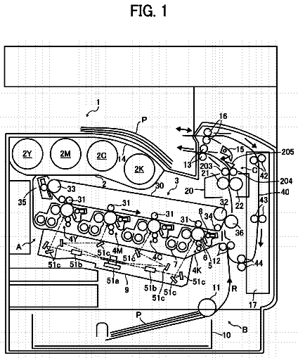
FIG. 1 is a drawing for describing the structure of a typical image forming apparatus to which the present invention is applicable.
FIG. 2 is a drawing for describing the structure of the image forming section of the image forming apparatus shown in FIG. 1 .
FIG. 3 is a drawing for describing the relationship between the exposure strength of an exposing device and the potential level of a given unexposed point of the electrostatic image formed by the exposure.
FIG. 4 is a drawing for describing the test image (toner images) formed in an image density adjustment control sequence.
FIG. 5 is a drawing for describing the data obtained in the image density adjustment control sequence.
FIG. 6 is a drawing for describing the structure of the replenishment developer supplying section.
FIG. 7 is a drawing for describing the amount by which replenishment developer is delivered by the replenishment developer supplying section, per rotation of the motor of the section.
FIG. 8 is a drawing for describing the relationship between the TD ratio and image density when the replenishment developer supplying section is nearly running out of replenishment developer.
FIG. 9 is a drawing for describing the image density adjustment control sequence in the first embodiment of the present invention.
FIG. 10 is a flowchart of the image density adjustment control sequence in the second embodiment of the present invention.
FIG. 11 is a drawing for describing the relationship between the laser output setting and exposure amount adjustment coefficient.
FIG. 12 is a flow chart of the laser output adjustment control sequence in the second embodiment.
FIG. 13 is a drawing for describing the effects of the second embodiment when the laser output setting is low.
FIG. 14 is a drawing for describing the effects of the second embodiment when the laser output setting is high.
FIG. 15 is a flowchart of the image density adjustment control sequence in the third embodiment of the present invention.
FIG. 16 is a drawing for describing the relationship between the DC voltage to be applied to the charge roller, and the laser output setting.
FIG. 17 is a drawing for describing the relationship between the laser output setting and coefficient of L adjustment.
FIG. 18 is a drawing for describing the relationship between the reduction in the sensitivity of a photosensitive drum, and the resultant changes in the potential level of a given point of an electrostatic image, which corresponds to an exposed point of the peripheral surface of the photosensitive drum.
FIG. 19 is a drawing for describing how the L adjustment coefficient is set in consideration of the reduction in the sensitivity of the photosensitive drum.
Description of the embodiments
Hereinafter, some of the preferred embodiments of the present invention are described in detail with reference to appended drawings.
<Embodiment 1>
(Image Forming Apparatus)
FIG. 1 is a drawing for describing the structure of the image forming apparatus in this embodiment. Referring to FIG. 1 , the image forming apparatus 80 is a monochromatic printer of the intermediary transfer type, in which its image forming section 85 is disposed on the top side of its intermediary transfer belt 81 . The image forming apparatus 80 in this embodiment can output as many as 25 prints of size A4 per minute in the landscape mode.
In the image forming section 85 , a toner image is formed on a photosensitive drum 13 , and is transferred onto the intermediary transfer belt 81 . Then, the toner image on the intermediary transfer belt 81 is conveyed to the secondary transferring section T 2 , in which the toner image is transferred (secondary transfer) onto a sheet P of recording medium. A separation roller 62 pulls the sheets in a cassette 60 one by one out of a cassette 60 , and sends each sheet P to a pair of registration rollers 41 , which sends each sheet P to the secondary transferring section T 2 with such timing that the sheet P arrives at the secondary transferring section T 2 at the same time as the toner image on the intermediary transfer belt 81 . After the secondary transfer of the toner image onto the sheet P, heat and pressure are applied to the sheet P and the toner image thereon. Thus, the toner image becomes fixed to the surface of the sheet P.
The intermediary transfer belt 81 is supported by a tension roller 37 , an inward secondary transfer roller 39 , and a driver roller 38 in such a manner that the intermediary transfer belt 81 bridges between adjacent two rollers. It rotates in the direction indicated by an arrow mark X by being driven by the driver roller 38 . The secondary transfer roller 40 forms the secondary transferring section T 2 by being placed in contact with the portion of the intermediary transfer belt 81 , which is being backed up by the inward secondary transfer roller 39 . As positive DC voltage is applied to the secondary transfer roller 40 , the toner image on the intermediary transfer belt 81 transfers onto a sheet P of recording medium. The belt cleaning device 50 recovers the transfer residual toner, that is, the toner remaining adhered to the surface of the intermediary transfer belt 81 after the secondary transfer, by rubbing the intermediary transfer belt 81 with its cleaning blade.
(Image Forming Section)
FIG. 2 is a drawing for describing the structure of the image forming section. Referring to FIG. 2 , the image forming section 85 has the photosensitive drum 13 as an example of an image bearing component. It has also a charging device 11 , an exposing device 12 , a developing device 2 , a transfer roller 14 , and a drum cleaning device 15 , which are disposed in the adjacencies of the peripheral surface of the photosensitive drum 13 . The photosensitive drum 13 comprises an aluminum cylinder, and a photosensitive layer formed on the peripheral surface of the aluminum cylinder. It rotates in the direction indicated by an arrow mark R 1 at a process speed of 110 mm/sec.
The charging device 11 negatively and uniformly charges the peripheral surface of the photosensitive drum 13 to a potential level VD (preset potential level) by applying oscillatory voltage, which is a combination of negative DC voltage and AC voltage Vac, to the charge roller. The lengthwise ends of the charge roller are under the pressure generated by unshown springy components in the direction of the photosensitive drum 13 . The charge roller is rotated by the rotation of the photosensitive drum 13 . For example, the DC voltage Vd is −600 V, and the AC voltage Vac is 1.5 kV in peak-to-peak voltage.
The exposing device 12 writes an electrostatic image of an image to be formed, on the peripheral surface of the photosensitive drum 13 , by scanning, with the use of a rotational mirror, the peripheral surface of the photosensitive drum 13 , by a beam of laser light it emits while modulating (turning on or off) the beam according to the image formation signals obtained by dividing the image to be formed, into minute cells. As the peripheral surface of the photosensitive drum 13 , which has just been charged to −600 V (pre-exposure potential level) is scanned by the exposing device 12 , the exposed points of the peripheral surface of the photosensitive drum 13 are discharged by the exposure. Consequently, an electrostatic image is effected, the exposed points of which are 100 V in potential level (post-exposure potential level).
The exposing device 12 is enabled to change the beam of laser light it emits, in intensity, within an intensity range of 0-255, in order to change a given point of the uniformly charged peripheral surface of the photosensitive drum 13 , in the potential level at which the given point will be as it is exposed. As the beam of laser light is changed in intensity L within the range of 0-255, the potential level of a given exposed point on the peripheral surface of the photosensitive drum 13 becomes V(L).
The gradation of an image is controlled by area gradation, by controlling the exposing device 12 in the laser beam intensity L, as will be described later. However, the present invention is also applicable to an image forming apparatus which controls image tone by changing the laser power.
The developing device 2 develops the electrostatic image on the photosensitive drum 13 into a visible image (image formed of toner). The lengthwise ends of the transfer roller 14 are kept under the pressure generated by unshown springy components in the direction of the photosensitive drum 13 . The transfer roller 14 forms a transferring section T 1 between the photosensitive drum 13 and intermediary transfer belt 81 by pressing on the intermediary transfer belt 81 . As positive DC voltage is applied to the transfer roller 14 , the negatively charged toner image on the photosensitive drum 13 is transferred onto the intermediary transfer belt 81 . The drum cleaning device 15 removes the secondary transfer residual toner, that is, the toner remaining on the peripheral surface of the photosensitive drum 13 after the toner image transfer, by rubbing the peripheral surface of the photosensitive drum 13 with its cleaning blade.
(Developing Device)
Referring to FIG. 2 , the developing device 2 is of the so-called two-component development type. That is, it uses developer which contains toner (nonmagnetic) and carrier (magnetic). The polarity to which toner is charged is negative, whereas the polarity to which carrier is charged is positive.
The internal space of the developing device 2 has a development chamber 212 and a stirring chamber 211 , which are separated by a partition wall 213 . The front and rear end portions of the partitioning wall 213 are provided with a pair of developer passages, one for one, which connect between the development chamber 212 and stirring chamber 211 .
The development chamber 212 has a development sleeve 232 . There is a first conveyance screw 222 on the underside of the development sleeve 232 . The first conveyance screw 222 conveys the developer in the development chamber 212 while stirring the developer. It coats the development sleeve 232 with the developer in the development chamber 212 while conveying the developer. As the developer in the development chamber 212 is used for development, the toner in the developer is consumed for the development. Thus, the developer in the development chamber 212 reduces in TD ratio. Then, the developer in the development chamber 212 is moved into the stirring chamber 211 by the first screw 222 through one of the aforementioned developer passages.
The stirring chamber 211 is provided with the second conveyance screw 221 . The second conveyance screw 221 conveys a combination of the toner delivered to the stirring chamber 211 from the developer supplying section 7 , and the developer in the developing device 2 , while stirring the combination, making the developer in the developing device 2 uniform in TD ratio. After the developer in the stirring chamber 211 is restored in TD ratio by being replenished with toner, it is moved into the development chamber 212 by the second conveyance screw 221 through the other developer passage.
The development sleeve 232 , first conveyance screw 222 , and second conveyance screw 221 are in connection with each other through an unshown gear train. They are driven by a developing device driving motor 27 . There is a stationary magnet 231 in the hollow of the development sleeve 232 . The magnet 231 is provided with three or more magnetic poles. In this embodiment, the magnet 231 is provided with five magnetic poles.
While the developer in the development chamber 212 is conveyed while being stirred, it is adhered to the peripheral surface of the development sleeve 232 by the magnetic force of the pickup pole N 3 , and then, is conveyed by the development sleeve 232 as the development sleeve 232 rotates. The developer on the peripheral surface of the development sleeve 232 is conveyed further by the development sleeve 232 while being securely held to the peripheral surface of the development sleeve 232 by the cut pole S 2 , and forming a magnetic brush. The regulation blade 25 trims the tip portion of the magnetic brush to correct in thickness the developer (developer layer) on the peripheral surface of the development sleeve 232 . After being corrected in thickness, the developer (developer layer) is conveyed to the development area of the photosensitive drum 13 by the rotation of the development sleeve 232 while being securely held to the peripheral surface of the development sleeve 232 by the magnetic pole N 1 . In the development area, the developer on the development sleeve 232 forms a magnetic brush by being held to the peripheral surface of the development sleeve 232 by the development pole S 1 , and rubs the peripheral surface of the photosensitive drum 13 .
A development power source 28 causes the toner in the magnetic brush to transfer onto the electrostatic image on the photosensitive drum 13 , by applying oscillatory voltage, which is a combination of DC voltage Vdc (for example, −550 V), and AC voltage Vac (1.3 kVpp), to the development sleeve 232 .
As described previously with reference to FIG. 2 , the exposing device 12 forms a latent image by exposing the photosensitive drum 13 which is an example of an image bearing component for bearing an image. The developing device 2 develops the latent image formed by exposing the photosensitive drum 13 , with the use of the developer which contains toner and carrier, and the potential of which is kept at the development level (DC). The replenishment developer supplying section 7 which is an example of a replenishing device, replenishes the developing device 2 with toner, based on the difference between the value (inductance) detected by the inductance sensor 26 , and a preset value, if the value (inductance) detected by the inductance sensor 26 is no more than a preset value.
(Image Density Adjustment Control)
FIG. 3 is a drawing for describing the relationship between the exposure intensity of the exposing device 12 and the potential level of a given exposed point of the peripheral surface of the photosensitive drum 13 . FIG. 14 is a drawing for describing a test image (patch) for image density adjustment control. FIG. 5 is a drawing for describing the data obtained by the image density adjustment control sequence.
Referring to FIG. 2 , the photosensitive drum 13 is charged to a potential level of −700 V (pre-exposure level), and then, an electrostatic image, the exposed points of which have a potential level of VL, is formed by exposing the photosensitive drum 13 with the exposing device 12 . The exposing device 12 can be changed in the intensity of exposure light (laser output), by setting the input to a semiconductor laser element, to one of 256 levels expressed in 8 bits.
Referring to FIG. 3 , the greater the input to the semiconductor laser element, the greater the output of the semiconductor laser. The greater the output of the semiconductor laser, the lower in potential level VL, the exposed points of the electrostatic image. When the output L of the semiconductor laser is 0, the value of the potential level VL of an exposed point of the electrostatic image is the same as the value of the potential level VD of an unexposed point of the electrostatic image.
Referring to FIG. 2 , the electrostatic image on the photosensitive drum 13 is developed into a toner image, the amount of toner per unit area of which is proportional to the development contrast Vcont, which is the difference between the magnitude of the DC voltage Vdc to be applied to the development sleeve 232 , and the value of the potential level VL of an exposed point of the electrostatic latent image (unexposed point of uniformly charged peripheral surface of photosensitive drum 13 ). The greater the exposing device 12 is made in the output L of the semiconductor laser, the lower in potential level VL, an exposed point of a resultant electrostatic image will be, and therefore, the greater, the development contrast Vcont will be. Therefore, as the exposing device 12 is increased in the output L of the semiconductor laser, the amount by which toner is adhered to the electrostatic latent image on the photosensitive drum 13 to develop the electrostatic image increases.
There is disposed an optical sensor 31 in the immediate adjacencies of the outward surface of the intermediary transfer belt 81 . The optical sensor 31 is capable of detecting the amount of toner which the toner image on the intermediary transfer belt 81 has per unit area. It projects a beam of infrared light from its LED toward the intermediary transfer belt 81 , and detects the portion of the beam, which was regularly reflected by the toner image on the intermediary transfer belt 81 . The greater in the amount of toner per unit area, the toner image, the more, the beam of infrared light from the LED is diffused, and therefore, the smaller the amount by which the beam of infrared light is regularly reflected by the toner image on intermediary transfer belt 81 . Thus, the output of the photo-diode corresponds to the amount of toner of the toner image on the intermediary transfer belt 81 .
The control section 100 carries out an operation for adjusting the image forming apparatus 80 in image density (Dmax control) by interrupting the ongoing image forming operation. In an operation for adjusting the image forming apparatus 80 in image density (which hereafter may be referred to simply as “image density adjustment control sequence”), test images (test patches) for density detection are formed on the photosensitive drum 13 , and are transferred onto the intermediary transfer belt 81 . Then, the test images are detected by the optical sensor 31 . The control section 100 obtains the amount of toner of each test image per unit area based on the value of the output of the optical sensor 31 , and converts the obtained amount of toner into a value which is equivalent to the reflection density of a fixed toner image (converted image density).
The control section 100 sets the output L of the laser so that the converted image density of a test image (toner image) which is highest in density (100% in areal gradation) takes a preset value. The control sequence is referred to as “image density adjustment control sequence (Dmax control sequence)”. In consideration of the balance between the stabilization of the image forming apparatus 80 in terms of image density, and the amount of downtime, the control section 100 interrupts an ongoing image forming operation with a frequency of once for every 300 images in order to carry out the image density adjustment control sequence.
Referring to FIG. 4 , five test images for density detection are formed in an extended image interval. The five test images correspond to laser outputs L of 80, 115, 150, 185 and 220 of the developing device 2 .
Referring to FIG. 5 , as the exposing device 12 is changed in the laser output L to the abovementioned five values, the amount by which toner is adhered to the peripheral surface of the photosensitive drum 13 changes to five different amounts, respectively. Thus, five different output values are obtained from the optical sensor 31 . As described above, there is such a relationship between the output of the optical sensor 31 and the amount of toner of the test patch per unit area. That is, the greater, a test image in the amount of toner per unit area, the smaller the amount by which the beam of infrared light is reflected. Thus, the lower, the value of the sensor output, the higher the converted image density.
The control section 100 obtains a value for the laser output L, which corresponds to the target value for the converted image density, based on the relationship between each of the five sensor output values, and the corresponding laser output L, shown in FIG. 5 . Then, it sets the laser output of the exposing device 12 to the obtained value. In this embodiment, the laser output L of the exposing device 12 is set so that the target converted image density (maximum density Dmax) becomes 1.4. In a case where the results of the detection (measurement) by the optical sensor 31 are as shown in FIG. 5 , the laser output L is set to 150 (L=150).
(Replenishment Developer Supplying Section)
FIG. 6 is a drawing for describing the replenishment developer supplying section. Referring to FIG. 2 , a toner bottle 70 which is an example of developer container is attached to the replenishment developer supplying section 7 in such a manner that it can be replaced. The toner bottle 70 stores the replenishment developer which is pure (100%) toner. In order to prevent toner from scattering, the replenishment developer is available to a user only in the toner bottle 70 which is sealed by a manufacturer. Thus, when the developing device 4 needs to be replenished with toner, the empty toner bottle in the developing device 2 is to be replaced with a brand-new (sealed) toner bottle 70 . There is disposed a toner bottle sensor 76 above the replenishment developer supplying section 7 . The control section 100 determines whether the toner bottle 70 is present or absent, and whether the toner bottle 70 in the replenishment developer supplying section 7 needs to be replaced or not.
Referring to FIG. 2 , the replenishment developer supplying section 7 replenishes the developing device 2 with the replenishment developer through the replenishment toner entrance ( 75 in FIG. 6 ), by rotating the toner conveyance bottom screw 72 . As the toner conveyance top screw 71 is rotated, the replenishment developer supplying section 7 moves the replenishment developer supplied from the toner bottle 70 . The toner conveyance bottom screw 72 and toner conveyance top screw 71 are in connection to each other through a gear train, and simultaneously rotate by being driven by a replenishment motor 73 . The rotation of the replenishment motor 73 is detectable in increments of a full rotation of the toner conveyance bottom screw 72 , by a rotation detecting means 74 (photo-interrupter).
(Replenishment Developer Delivery Control)
Referring to FIG. 2 , each time an electrostatic image is developed, the developer in the developing device 2 reduces in TD ratio by an amount equivalent to the amount by which the toner is consumed for the development. The control section 100 calculates the amount of toner necessary to develop an electrostatic image. Then, it replenishes the developing device 2 with the replenishment developer (100% in toner content) from the replenishment developer supplying section 7 , by an amount equivalent to the calculated amount of toner consumption, in order to restore the developer in the developing device 2 in TD ratio. More concretely, each time an electrostatic image is developed, the control section 100 calculates the amount by which the developing device 2 needs to be replenished with toner, and rotates the replenishment motor 73 by an amount equivalent to the calculated amount by which the developing device 2 needs to be replenished with toner.
However, it is possible that there will be a difference between the amount by which the developing device 2 is replenished with the replenishment developer based on the calculated amount of toner consumption per electrostatic image, and the actual amount by which toner was consumed per electrostatic image. Thus, if an image forming operation is continued while there is the above-described difference, the TD ratio of the developer in the developing device 2 gradually deviates from its initial value. Thus, in order to deal with this issue, the stirring chamber 211 of the developing device 2 is provided with an inductance sensor 26 . The control section 100 determines the TD ratio of the developer in the developing device 2 by detecting the output of the inductance sensor 26 . Then, it adjusts the amount by which the replenishment developer is to be supplied from the replenishment developer supplying section 7 , based on the obtained TD ratio of the developer in the developing device 2 , in order to keep the developer in the developing device 2 stable in TD ratio at a preset level. Next, the amount by which the developing device 2 is replenished with the replenishment developer as the N-th image is formed in a continuous image forming operation, is described.
Referring to FIG. 2 , the control section 100 calculates video count value Vc based on the information about the image on the Nth print, and calculates video count replenishment amount Mvc by multiplying the obtained video count value Vc by a coefficient Avc. The video count value Vc is the amount (number) of 1 in a single binary signal in the image formation signals. Thus, the video count value Vc of an image which is 100% (solid image with maximum density) is 1023. The video count value Vc is affected by the image ratio. The coefficient Avc is stored in advance in a ROM 102 . Mvc=Vc×Avc
Referring to FIG. 2 , the control section 100 computes the converted TD ratio Tdin of the developer, based on the output of the inductance sensor 26 , which is obtained when the Nth toner image is formed. Then, it calculates the inductance replenishment amount Min by multiplying the difference between the converted TD ratio Tdin and target TD ratio Tdtgt, by a coefficient Ain. The coefficient Ain is stored in advance in the ROM 102 . The target TD ratio is recorded in a RAM 103 . It is changeable in value. Min=( TDtgt−TDin )× Ain
The control section 100 calculates the amount M by which the developing device 2 is replenished with toner when the Nth image is formed, using the following equation (3), in which if the amount M is smaller than zero, the amount M is set to zero (M=0). The third item Mrem on the right side of equation
stands for the residual amount of toner, that is, the amount of toner that failed to be delivered when the Nth image was formed. The reason why a certain amount of toner fails to be delivered is as follows. That is, the replenishment developer is delivered to the developing device 2 by the amounts measured in an increment which corresponds to a single full rotation of the toner conveyance bottom screw 72 . Therefore, the amount which is less than the equivalency of a full rotation of the toner conveyance bottom screw 72 has to be taken into consideration. M=Mvc +Min+ Mrem
The control section 100 calculates the number Brq of times replenishment motor 73 has to be rotated, based on the toner replenishment amount M, with the use of the following equation, in which the incremental replenishment amount T is the amount by which the developing device 2 is replenished with the replenishment developer by a single full rotation of the toner conveyance bottom screw 72 . The incremental replenishment amount T is stored in advance in the ROM 102 . In this embodiment, the incremental replenishment amount T is set to 0.10 g (T=0.10 g). The portion of the value of the required number of rotations Brg, which is on the right side of the decimal point, is ignored; only the integer portion is used. Brg=M/T
The control section 100 calculates the number Bpr of rotations, by which the toner conveyance bottom screw 72 is to be actually rotated for the replenishment, based on the required number Brq of rotations. The calculating method will be described later. When the Nth image is formed, the control section 100 supplies the developing device 2 with the replenishment developer, by activating the replenishment motor 73 for a length of time which is proportional to the number Bpr of rotations.
The above-described residual amount Mrem is calculated based on the number Bpr of rotations of the toner conveyance bottom screw 72 , with the use of the following equation. Mrem=M−Bpr×T
By the way, the target TD ratio TDtgt is changeable in value. In this embodiment, in a case where the target TD ratio TDtgt needs to be changed in value, referential test images for density detection are formed on the photosensitive drum 13 . Then, they are transferred onto the intermediary transfer belt 81 , and are detected by the optical sensor 31 . Then, the target TD ratio TDtgt is changed in value based on the result of the detection.
(Sequence for Confirming Residual Toner Amount)
FIG. 7 is a drawing for describing the amount by which the developing device 2 is replenished with toner by a single rotation of the replenishment motor of the replenishment developer supplying section 7 . FIG. 8 is a drawing for describing the TD ratio and image density toward the end of the life span of the toner bottle 70 . More specifically, FIG. 8( a ) shows the changes in the TD ratio, and FIG. 8( b ) shows the changes in the image density.
Referring to FIG. 7 , immediately before the replenishment developer supplying section 7 runs out of toner, the amount by which toner is delivered by a single rotation of the replenishment motor 73 gradually reduces until it becomes zero. Referring to FIG. 8( a ) , immediately before the replenishment developer supplying section 7 runs out of toner, the amount by which toner is delivered by a single rotation of the replenishment motor 73 becomes insufficient, and therefore, it becomes impossible for the TD ratio of the developer in the developing device 2 to be maintained at a preset level. Consequently, the TD ratio begins to reduce.
As the control section 100 determines that the converted TD ratio Tdin, which is obtained from the output of the inductance sensor 26 has become no more than a preset threshold value (8.0%), it carries out the sequence for confirming the remaining amount of toner (toner amount confirmation sequence). In the toner amount confirmation sequence, the ongoing image forming operation is interrupted for every 10 images. Then, the replenishment motor 73 is driven to replenish the developing device 2 with toner while the developing device driving motor 27 is driven. After the operation for replenishing the developing device 2 with toner is stopped, the control section 100 examines the results of the detection by the inductance sensor 26 to determine whether or not toner is in the replenishment developer supplying section 7 .
In the toner amount confirmation sequence, if the control section 100 determines that the relationship between the TD ratio detected when the Nth image is formed and the target TD ratio TDtgt satisfies the following mathematical formula, it determines that the replenishment developer supplying section 7 is out of the replenishment developer (toner). Δ TD ratio ( N )= TDin ( N )− TDtgt≦− 1.0%
Referring to FIG. 2 , the control section 100 , which is an example of a demanding section, determines that the result of the detection by the inductance sensor 26 becomes the first threshold value 7% which is smaller than a preset value (8%), it demands the replacement of the toner bottle 70 . That is, as the TD ratio of the developer detected by the inductance sensor 26 becomes no more than the first threshold value (7%), the control section 100 displays a message which suggests that the toner bottle 70 is to be replaced, on the control panel 301 .
More concretely, referring to FIG. 8( a ) , the control section 100 determines that the converted TD ratio TDin is no more than 7%, it determines that there is no toner in the replenishment developer supplying section 7 . Then, it stops the ongoing image forming operation, and demands the replacement of the toner bottle 70 in the replenishment developer supplying section 7 , through the control panel 301 . That is, it displays a message “Please replace toner bottle”, that is, a message which suggests that a user replaces the toner bottle 70 in the replenishment developer supplying section 7 , on the display 300 . Then, it prevents the image forming apparatus 80 from restarting the interrupted image forming operation.
The description continues in the full USPTO document.