Cross reference to related applications
This application is a U. S. National Phase of International Patent Application No. PCT/JP2014/082260 filed on Dec. 5, 2014, which claims priority benefit of Japanese Patent Application No. JP 2014-098664 filed in the Japan Patent Office on May 12, 2014. Each of the above-referenced applications is hereby incorporated herein by reference in its entirety.
Technical field
The present disclosure relates to a reception device, a transmission device, and a data processing method. More specifically, the present disclosure relates to a reception device and a transmission device for transmitting or receiving data via broadcast waves, for example, and a data processing method.
Background art
There are various systems for superposing and displaying subtitles on a video, and Timed Text Markup Language (TTML) as subtitle data in the Extensible Markup Language (XML) form, which enables a display region, a display timing and the like to be controlled, are increasingly used.
TTML can be associated with a web application such as HTML5, and has a property that it can use not only character codes but also bit maps.
Note that, TTML is described in Patent Document 1 (Japanese Patent Application Laid-Open No. 2012-169885), for example. CITATION LIST Patent Document
Patent Document 1: Japanese Patent Application Laid-Open No. 2012-169885 SUMMARY OF THE INVENTION Problems to be Solved by the Invention
The TTML subtitle data as subtitle data is used in VOD and the like, for example, but a specific method for delivering TTML subtitle data in TV broadcasting, for example, has not been obviously proposed.
It is an object of the present disclosure to provide a reception device and a transmission device capable of transmitting/receiving TTML subtitle data via broadcast waves and conducting various subtitle display control based on the TTML subtitle data on the reception side, and a data processing method. Solutions to Problems
A first aspect of the present disclosure lies in
a reception device including:
a communication unit for receiving a TTML subtitle data storage packet storing Timed Text Markup Language (TTML) subtitle data as payload of a MMT packet defined in the MPEG Media Transport (MMT) format, and a signaling message including subtitle-related information corresponding to the TTML subtitle data; and
a data processing unit for conducting subtitle display control by use of the TTML subtitle data and the signaling message.
Further, a second aspect of the present disclosure lies in
A transmission device including:
a data processing unit for generating a TTML subtitle data storage packet storing Timed Text Markup Language (TTML) subtitle data as payload of a MMT packet defined in the MPEG Media Transport (MMT) format, and a signaling message including subtitle-related information corresponding to the TTML subtitle data; and
a communication unit for transmitting the TTML subtitle data storage packet and the signaling message.
Further, a third aspect of the present disclosure lies in
a data processing method performed by the reception device,
wherein the communication unit receives a TTML subtitle data storage packet storing Timed Text Markup Language (TTML) subtitle data as payload of a MMT packet defined in the MPEG Media Transport (MMT) format, and a signaling message including subtitle-related information corresponding to the TTML subtitle data, and
the data processing unit conducts subtitle display control by use of the TTML subtitle data and the signaling message.
Further, a fourth aspect of the present disclosure lies in
a data processing method performed by the transmission device,
wherein the data processing unit generates a TTML subtitle data storage packet storing Timed Text Markup Language (TTML) subtitle data as payload of a MMT packet defined in the MPEG Media Transport (MMT) format, and a signaling message including subtitle-related information corresponding to the TTML subtitle data, and
the communication unit transmits the TTML subtitle data storage packet and the signaling message.
Other objects, characteristics, and advantages of the present disclosure will be apparent in more detailed description based on the exemplary embodiments of the present disclosure or the accompanying drawings described below. Note that, a system in the present specification is a logical collective structure of a plurality of devices, and the devices in each structure are not necessarily present in the same casing. Effects of the Invention
With the structure according to one exemplary embodiment of the present disclosure, a device and a method for realizing accurate TTML subtitle data display control are realized.
Specifically, a TTML subtitle data storage packet storing TTML subtitle data as payload of a MMT packet defined in the MMT format therein, and subtitle-related information corresponding to the TTML subtitle data are transmitted as a signaling message from a transmission device to a reception device. The signaling message defines a time mode (TMD) as a subtitle display timing control mode, or an operation mode (OPM) of selectively performing instant display of subtitles or TTML description-based display thereof, and the reception device can conduct display control in a designated mode.
With the structure, the device and the method for realizing accurate TTML subtitle data display control are realized.
Note that, the effects described in the present specification are merely exemplary and not restrictive, and additional effects may be given.
Brief description of drawings
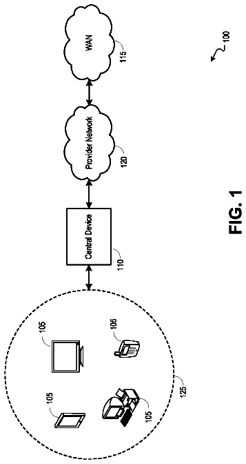
FIG. 1 is a diagram for explaining an exemplary structure of a communication system for performing the processing according to the present disclosure.
FIG. 2 is a diagram illustrating a stack model in the MMT format.
FIG. 3 is a diagram for explaining an exemplary structure of a transmission device.
FIG. 4 is a diagram for explaining an exemplary structure of a reception device.
FIG. 5 is a diagram for explaining a structure of a MMT packet.
FIG. 6 is a diagram for explaining a structure of a MMT packet.
FIG. 7 is a diagram for explaining data transmission in the MMT format.
FIG. 8 is a diagram for explaining data transmission in the MMT format.
FIG. 9 is a diagram for explaining a PA message.
FIG. 10 is a diagram for explaining MMT package table (MPT).
FIG. 11 is a diagram for explaining MMT package table (MPT).
FIG. 12 is a diagram for explaining MMT package table (MPT).
FIG. 13 is a diagram for explaining data transmitted from the transmission device to the reception device.
FIG. 14 is a diagram for explaining subtitle-related data transmitted from the transmission device to the reception device.
FIG. 15 is a diagram for explaining a structure and exemplary use of TTML subtitle data.
FIG. 16 is a diagram for explaining subtitle-related information recorded in MPT.
FIG. 17 is a diagram for explaining a subtitle type recorded in MPT.
FIG. 18 is a diagram for explaining time modes recorded in MPT.
FIG. 19 is a diagram for explaining display modes recorded in MPT.
FIG. 20 is a diagram for explaining operation modes recorded in MPT.
FIG. 21 is a diagram for explaining display formats recorded in MPT.
FIG. 22 is a diagram for explaining compression modes recorded in MPT.
FIG. 23 is a diagram for explaining a structure of MH-Envent Information table (EIT).
FIG. 24 is a diagram for explaining the processing while TMD=1: TTML description+EIT starttime mode is set.
FIG. 25 is a diagram for explaining a data structure of UTC-NPT-reference/EMT.
FIG. 26 is a diagram for explaining the processing while TMD=2: TTML description+NPT mode is set.
FIG. 27 is a diagram for explaining the processing while TMD=3: TTML description+absolute time mode is set.
FIG. 28 is a diagram for explaining the processing while TMD=4: TTML description+reference starttime mode is set.
FIG. 29 is a diagram for explaining the processing while TMD=4: TTML description+reference starttime mode is set.
FIG. 30 is a diagram for explaining a MPU timestamp descriptor.
FIG. 31 is a diagram for explaining the processing while TMD=5: TTML description+MPU_time stamp mode is set.
FIG. 32 is a diagram for explaining the processing while TMD=8: MPU_time stamp mode is set.
FIG. 33 is a diagram for explaining the processing while TMD=15: no time control mode is set.
FIG. 34 is a diagram for explaining the processing while OPM=0: Live mode is set.
FIG. 35 is a diagram for explaining the processing while OPM=1: Segmentation mode is set.
FIG. 36 is a diagram for explaining the processing while OPM=2: Program mode is set.
FIG. 37 is a diagram illustrating a flowchart for explaining a processing sequence performed by the transmission device.
FIG. 38 is a diagram illustrating a flowchart for explaining a processing sequence performed by the reception device.
FIG. 39 is a diagram for explaining an exemplary hardware structure of a communication device as the transmission device and the reception device.
Mode for carrying out the invention
A reception device, a transmission device, and a data processing method according to the present disclosure will be described below in detail with reference to the drawings. Note that, the description will be made according to the following items.
1. Exemplary structure of communication system
2. Structures of transmission device and reception device, and MPEG Media Transport (MMT)
3. Details of MMT format
4. MMT package table (MPT)
5. Outline of data and TTML subtitle data transmitted from transmission device to reception device
6. Subtitle-related information recorded in MMT package table (MPT)
7. Specific processing in each of time modes (TMD)
7-1. Processing while TMD=1: TTML description+EIT starttime mode is set
7-2. Processing while TMD=2: TTML description+NPT mode is set
7-3. Processing while TMD=3: TTML description+absolute time mode is set
7-4a. Processing while TMD=4: TTML description+reference starttime mode is set (first example)
7-4b. Processing while TMD=4: TTML description+reference starttime mode is set (second example)
7-5. Processing while TMD=5: TTML description+MPU timestamp mode is set
7-6. Processing while TMD=8: MPU timestamp mode is set
7-7. Processing while TMD=15: no time control mode is set
8. Specific processing in each mode of operation modes (OPM)
8-1. Processing while OPM=0 Live mode is set
8-2. Processing while OPM=1: Segmentation mode is set
8-3. Processing while OPM=2: Program mode is set
9. Processing sequences of processing performed by transmission device and reception device
10. Exemplary structures of transmission device and reception device
11. Summary of structure of present disclosure
[1. Exemplary Structure of Communication System]
An exemplary structure of a communication system for performing the processing according to the present disclosure will be first described with reference to FIG. 1 .
As illustrated in FIG. 1 , a communication system 10 has a transmission device 20 which is a communication device for transmitting video data, audio data, subtitle data, and data such as various items of control information, and a reception device 30 which is a communication device for receiving data transmitted from the transmission device 20 .
The transmission device 20 is specifically a device for providing contents of various programs, such as broadcast station 21 , for example.
On the other hand, the reception device 30 is a client device of a typical user, and is specifically configured of a TV 31 , a PC 32 , or a portable terminal 33 , for example.
Data communication between the transmission device 20 and the reception device 30 is made as one-way communication using broadcast waves.
Data transmission from the transmission device 20 to the reception device 30 is performed mainly in the MPEG Media Transport (MMT) format.
The MMT format defines a data transfer system (transport format) when coding data as content structure data, such as video, audio, and subtitles, is transmitted via a broadcast wave or network.
The transmission device 20 codes content data, generates a data file including coded data and metadata of the coded data, and stores the generated coded data in a MMT packet defined in MMT to be transmitted via a broadcast wave or network.
Data provided from the transmission device 20 to the reception device 30 is configured of guidance information such as program guide, notification information, and control information in addition to data to be reproduced such as video, audio, and subtitles.
[2. Structures of Transmission Device and Reception Device, and MPEG Media Transport (MMT)]
As described above, data transmission from the transmission device 20 to the reception device 30 is performed mainly in the MPEG Media Transport (MMT) format.
The structures of the transmission device and the reception device, and the data exchange processing using the MMT format for MPEG Media Transport (MMT) will be described in detail with reference to FIG. 2 and others.
FIG. 2 is a diagram illustrating a stack model in the MMT format.
In the MMT stack model illustrated in FIG. 2 , a physical layer (PHY) is present in the lowermost layer. The physical layer is divided into a broadcasting layer for broadcast processing, and a broadband layer for network processing.
MMT enables the processing using two communication networks for broadcast and network.
A Type Length Value (TLV) layer is present on top of the broadcasting layer for broadcast processing. TLV is a format definition layer defining an IP packet multiplexing system therein. A plurality of IP packets are multiplexed to be transmitted as a TLV packet. TLV-SI is a signaling message transmission layer in the TLV format.
A signaling message is configured of setting information required for receiving contents (programs) in the reception device 30 , guidance information such as program guide, notification information, control information, and the like.
A signaling message stored in the TLV packet generated in the TLB layer is TLV-SI, and a signaling message stored in the MMT packet is MMT-SI indicated in the uppermost layer.
A UDP/IP layer is set on top of the TLV layer.
The UDP/IP layer is dividable into an IP layer and a UDP layer in detail, but is a layer for defining transmission for storing a UDP packet in payload of an IP packet.
A MMT layer and a File delivery method layer are set on top of the UDP/IP layer.
Both a system for transmitting a MMT packet stored in an IP packet, and a system for performing data transmission in an IP packet by use of the File delivery method as a data transmission system not using a MMT packet are usable.
The following layers are set on top of the MMT layer: HEVC as video codec, and video data thereon AAC as audio codec, and audio data thereon Signaling message (MMT-SI) transmitted by use of MMT packet Subtitle data Electronic Program Guide (EPG) as program information Each item of the data is stored in a MMT packet to be transmitted.
Note that, Time (NTP: Network Time Protocol) is absolute time information, and is directly stored in a UDP packet to be transmitted.
Data service for performing other data delivery, contents download, and the like can be delivered by use of a different file delivery method from MMT.
FIG. 3 illustrates an exemplary structure of the transmission device 20 illustrated in FIG. 1 .
As illustrated in FIG. 3 , the transmission device 20 has a content providing unit 51 , an information processing unit 52 , a clock signal generation unit (NTP) 53 , a video data processing unit 54 , an audio data processing unit 55 , a subtitle data processing unit 56 , a signaling message processing unit 57 for performing the processing mainly on a signaling message stored in a MMT packet, a TLV signaling message processing unit 58 for performing the processing on a signaling message stored in a TLV packet, an IP service multiplexer (MUX) 59 , a TLV multiplexer (MUX) 60 , and a communication unit (modulation/transmission unit) 61 .
The content providing unit 51 is configured of a storage unit storing program contents therein, for example. Additionally, it may be configured of a data acquisition unit such as TV camera or microphone for live broadcast. Alternatively, it may be configured as a communication unit with external servers or the like for supplying contents.
The content providing unit 51 outputs contents such as video, audio, and subtitle to the video data processing unit 54 , the audio data processing unit 55 , and the subtitle data processing unit 56 , respectively.
Note that, subtitle data may be generated in the information processing unit 52 .
The information processing unit 52 generates information (signaling message) required for accurately receiving and reproducing the contents provided by the content providing unit 51 in the reception device 30 , such as generated subtitles, generated control information, or generated guidance information for the contents provided by the content providing unit 51 .
The subtitle data generated by the information processing unit 52 is provided to the subtitle data processing unit 56 . The signaling message is provided to the signaling message processing unit 57 and the TLV signaling message processing unit 58 .
The clock signal generation unit 53 generates time information synchronized with time information obtained from a NTP server (not illustrated) for transmitting absolute time information, and transmits an IP packet including the generated time information to the IP service multiplexer 59 .
Further, a clock signal generated in the clock signal generation unit 53 is also output to the video data processing unit 54 , the audio data processing unit 55 , and the subtitle data processing unit 56 , and the video data processing unit 54 , the audio data processing unit 55 , and the subtitle data processing unit 56 generate an IP packet setting clock information therein.
The video data processing unit 54 codes and packetizes a video signal sent from the content providing unit 51 , and sends an IP packet including a MMT packet storing video data therein to the IP service multiplexer 59 . Further, the audio data processing unit 54 codes and packetizes an audio signal sent from the content providing unit 51 , and sends an IP packet including an audio MMT packet therein to the IP service multiplexer 59 .
Further, the subtitle data processing unit 56 codes and packetizes subtitle data sent from the content providing unit 51 or the information processing unit 52 , and sends an IP packet including a subtitle MMT packet therein to the IP service multiplexer 59 .
Note that, with the structure according to the present disclosure, subtitle data employs Timed Text Markup Language (TTML) as subtitle data in the Extensible Markup Language (XML) form enabling a display region or a display timing to be controlled.
TTML subtitle data will be described below in detail.
The signaling message processing unit 57 generates a signaling message on the basis of the information sent from the information processing unit 52 , and generates an IP packet including a MMT packet in which the signaling message is arranged in the payload, and sends it to the IP service multiplexer 59 .
The TLV signaling message processing unit 58 generates a signaling message on the basis of the information sent from the information processing unit 52 , and generates a TLV packet in which the signaling message is arranged in the payload, and sends it to the TLV multiplexer 60 .
The transmission device 20 provides the IP service multiplexer 59 per channel to send (broadcast channel). The IP service multiplexer 59 for one channel generates an IP packet including each of video, audio, subtitle, and signaling message sent from each of the data processing units 54 to 57 , and sends it to the TLV multiplexer 60 .
The TLV multiplexer 60 multiplexes the IP packet output from the IP service multiplexer 59 and the TLV signaling message output from the TLV signaling message processing unit 58 , and generates and outputs a TLV packet including the data to the communication unit 61 .
The communication unit 61 performs a RF modulation processing or the like on the TLV packet generated in the TLV multiplexer 60 , and outputs a resultant broadcast wave.
FIG. 4 illustrates an exemplary structure of the reception device 30 illustrated in FIG. 1 . The reception device 30 illustrated in FIG. 4 has a communication unit 71 , a demultiplexer 72 , and the components of the demultiplexer 72 including a TLV processing unit 73 , a UDP/IP processing unit 74 , a MMT processing unit 75 , a MMT-SI filter 76 , and a TLV-SI filter 77 .
It further has a clock signal generation unit 78 , a video data processing unit 79 , an audio data processing unit 80 , a subtitle data processing unit 81 , a control unit 82 , and a superposition unit 83 .
The communication unit (tuner/demodulation unit) 71 receives a RF modulation signal and performs the demodulation processing thereon, thereby obtaining a broadcast stream. The demultiplexer 72 performs the demultiplex processing and the packet separation processing on the broadcast stream.
Each MMT packet or signaling message described below is obtained in the processing of each of the components of the demultiplexer 72 including the TLV processing unit 73 , the UDP/IP processing unit 74 , the MMT processing unit 75 , the MMT-SI filter 76 , and the TLV-SI filter 77 , and is output to a respective processing unit.
To output NTP time information stored in an IP packet to the clock signal generation unit 78
To output video data stored in a MMT packet to the video data processing unit 79
To output audio data stored in a MMT packet to the audio data processing unit 80
To output subtitle data stored in a MMT packet to the subtitle data processing unit 81
To output signaling message stored in a MMT packet or a TLV packet to the control unit 82
Note that, the MMT-SI filter 76 selects the MMT signaling message stored in the MMT packet, and the TLV-SI filter 77 selects and outputs the TLV signaling message stored in the TLV packet. The same signaling message is repeatedly transmitted, and thus each filter confirms the version set in the packet, and selects and obtains a signaling message with a new version, and outputs it to the control unit 82 without obtaining the already obtained signaling messages.
The control unit 82 controls the operation of each unit in the reception device 30 on the basis of the signaling message obtained in the demultiplexer 72 , or operation information from the user via a user operation unit (not illustrated).
The signaling message obtained by the control unit 82 is input into the video data processing unit 79 , the audio data processing unit 80 , and the subtitle data processing unit 81 , and is applied to the processing in each data processing unit.
The clock signal generation unit 78 generates time information synchronized with the NTP time information on the basis of the NTP time information obtained in the demultiplexer 72 .
Note that, a clock signal generated by the clock signal generation unit 78 is input into the video data processing unit 79 , the audio data processing unit 80 , and the subtitle data processing unit 81 , and the data generated in each data processing unit can be synchronized and output.
The video data processing unit 79 performs the decode processing or the like on a coded video signal obtained in the demultiplexer 72 thereby to generate an output video signal. Further, the audio data processing unit 405 performs the decode processing or the like on a coded audio signal obtained in the demultiplexer 72 thereby to generate an output audio signal. Further, the subtitle data processing unit 81 decodes a coded subtitle signal obtained in the demultiplexer 72 thereby to obtain a subtitle display signal.
Note that, the subtitle data processing unit 81 conducts subtitle output control for determining a display timing, a display region, and the like of subtitles, and outputs the subtitles to the superposition unit 83 at the determined display timing.
The display control processing will be described below in detail.
A clock signal generated by the clock signal generation unit 78 is input into the video data processing unit 79 , the audio data processing unit 80 , and the subtitle data processing unit 81 , and the data generated in each data processing unit is synchronized and output.
The superposition unit 83 performs the processing of superposing the subtitle data generated by the subtitle data processing unit 81 on the video signal generated by the video data processing unit 76 and outputting it.
Note that, as described above, with the structure according to the present disclosure, the subtitle data employs Timed Text Markup Language (TTML), which is subtitle data in the Extensible Markup Language (XML) format enabling a display region, a display timing, and the like to be controlled.
TTML subtitle data will be described below in detail.
[3. Details of MMT Format]
The communication system 10 illustrated in FIG. 1 assumes that MMT is mainly applied as the transport system for transmitting a broadcast signal from the transmission device 20 to the reception device 30 .
When MMT is used as the transport system, data is stored in a MMT packet to be transmitted.
A structure of a MMT packet will be described with reference to FIG. 5 and others.
A MMT packet is a unit of media data formatted to be transmitted by use of the MMT protocol.
(a) in FIG. 5 is a diagram illustrating an entire structure of a MMT packet.
When 1 is substituted into a packet counter flag “C,” it is expressed that the packet counter field indicated in an arrow from Cis present in the MMT packet. The packet counter is a 32-bit length field to be written with an integer value of the counted MMT packets, and is incremented by 1 each time a MMT packet is transmitted.
When 1 is substituted into an extension flag “X,” it is expressed that an extension header indicated in an arrow is present. (b) in FIG. 5 illustrates an exemplary structure of the extension header. The extension header is configured of a 16-bit length type field, a length field, and a header_extension_value field. A byte length of the header_extension_value field is written in the length field. Extension information not conforming to the MMT specification can be written in the header_extension_value field.
A type value indicating a type of the payload data of the MMT packet is written in the type field. The definitions of the type value are as follows.
0x00: MPU
0x01: Generic object
0x02: signaling message
0x00: repair symbol
The payload with type=0x00 is a media presentation unit (MPU). MPU is a unit set as one unit of video, audio, subtitle, or the like, for example. For example, one picture is 1 MPU for video. One TTML file is set as 1 MPU for subtitles.
Note that, 1 MPU is divided into a plurality of media fragment units (MFUs) as needed to be stored in the MMT packet.
The payload with type=0x02 is a signaling message. This is configured of setting information in the reception device, notification information, guidance information, attribute information on transmission data (video, audio, subtitles), control information, and the like.
Other types do not have a direct relationship with the processing according to the present disclosure, and thus the description thereof will be omitted.
When 1 is substituted into a Random Access Point (RAP) flag, it is expressed that the payload of the MMT packet includes Random Access Point to a data stream with the data type.
An integer value for discriminating an asset is written in the 16-bit length packet_id field. A value in the field results from asset_id of the asset to which the MMT packet belongs.
Mapping between a packet identifier (packet_id) and an asset identifier (asset_id) is indicated by MMT package table (MPT) as part of the signaling message.
MPT will be described below in detail.
Note that, asset is a data unit set for a signal series. Video data, audio data, and subtitle data are set as different assets, respectively. Further, when video data including a plurality of different items of video data, such as multi-view video, is transmitted, the shot videos are set as different assets, such as asset 1 for camera 1 and asset 2 for camera 2.
In the case of subtitle data, individual assets are set depending on the kind of subtitles.
Note that, the kinds of subtitles are discriminated by various elements such as languages including Japanese or English, subtitle type, and time mode defining a subtitle display timing, and TTML subtitle data in which the respective elements are identical is assumed as one asset.
A transmission time of the MMT packet is described in the 32-bit length timestamp field in the short-format defined in the NTP protocol.
An integer value (sequence number on the MMT transmission path) for discriminating a packet having the same packet_id is described in the 32-bit length packet_sequence_number field.
A serial number of the MMT packet is described in the 32-bit length packet_counter field.
(c) in FIG. 6 illustrates an exemplary structure of the payload of the MMT packet storing MPU as one unit of video, audio, or subtitles or MFU as divided data of MPU therein. A MMT packet storing MPU or MFU as divided data of MPU therein is called MPU mode MMT packet. This is when “0x00” is written in the type field in the MMT header. The MPU mode MMT packet is used for transmitting data such as video, audio, or subtitles.
A fragment type is indicated in a 4-bit value in the MPU Fragment Type (FT) field. The definitions of the FT value are as follows:
0: MPU metadata
1: Movie fragment metadata
2: Mfu
When 1 is written in the Timed (T) flag, it is expressed that MPU for transmitting timed media is fragmented, and when 0 is written therein, it is expressed that MPU for transmitting non-timed media is fragmented.
With data transmission using a MMT packet, both timed media such as video or audio as stream media, and non-timed media such as file can be transmitted.
The Timed (T) flag is directed for identifying whether MPU is timed media or non-timed media.
Information on fragmentation of the data unit in the payload is indicated in 2 bits in the Fragmentation Identifier (f_i) field. The definitions of four values of f_i are as follows:
0: To store an integer number of data units (MPU)
1: To store the first fragment (MFU) of data unit (MPU)
2: To store middle fragment (MFU) of data unit (MPU)
3: To store the last fragment (MFU) of data unit (MPU)
The number of payloads including the fragments of the same data unit followed by the MMT payload is described in the 8-bit length fragment_counter field.
A length of data (DU: Data Unit) leading to the 16-bit length DU_length field is described in the 16-bit length DU_length field. When the A flag is 0, the DU_length field is not present.
DU_Header is the header of a data unit. When the FT value is 0 or 1 (or when it is not MFU), DU_Header is not present. MFU includes a sample or sub-sample of timed media, or an item of non-timed media.
MPU or MFU as divided data of MPU is stored in DU_payload. Specifically, coded data of video, audio, or subtitles is stored. In the case of subtitle data, Timed Text Markup Language (TTML) is employed in the structure according to the present disclosure. TTML subtitle data will be described below in detail.
(d) in FIG. 6 illustrates an exemplary structure of DU_Header of MFU in which timed media is arranged in the payload. Further, (e) in FIG. 6 illustrates an exemplary structure of DU_Header of MFU in which non-timed media is arranged in the payload. As illustrated in (e) in FIG. 6 , DU_Header for non-timed media is configured of 32-bit length item_ID which is the identifier of an item transmitted as part of the MFU. The item is a resource configuring the application of HTML document data or mono-media data referred to by a HTML document. An item can be uniquely specified in a combination of packet_id in the header of the MMT packet, download id in the extension header, and item_ID in the DU header on the MMT transmission path designated by asset_id.
As described above, type set in the header of the MMT packet illustrated in FIG. 5 is type information capable of identifying whether the payload is MPU configured of video, audio, and subtitles, or a signaling message.
The payload with type=0x00 is a media presentation unit (MPU) configured of video, audio, and subtitles.
The payload with type=0x02 is a signaling message.
FIG. 7 is a diagram for explaining the structures of packets storing MPU, and an exemplary structure of packets storing a signaling message.
The following packet structures are illustrated by way of example:
(A) Video data (MPU)
(B) Subtitle data (MPU)
(C) Signaling data
(A) and (B) illustrate MPU of video and subtitles by way of example, and MPU is a unit set as one unit of video, audio, or subtitles, for example. For example, one picture is 1 MPU for video. One TTML file is set as 1 MPU for subtitles.
One MPU is divided into a plurality of media fragment units (MFU) as needed to be stored in a MMT packet.
The MMT packet is stored in a UDP packet, and the UDP packet is further stored in an IP packet.
Further, though not illustrated, the IP packet is stored in a TLV packet to be transmitted.
On the other hand, the payload with type=0x02 is (C) signaling message. This is configured of setting information in the reception device, notification information, guidance information, attribute information on transmission data (video, audio, and subtitles), control information, and the like.
The signaling message is not in the unit setting such as MPU/MFU, and is defined in its order by a sequence number, for example, to be stored in a MMT packet.
The MMT packet is stored in a UDP packet, and the UDP packet is further stored in an IP packet.
Further, though not illustrated, the IP packet is stored in a TLV packet to be transmitted.
Note that, with the structure according to the present disclosure, subtitle data employs Timed Text Markup Language (TTML).
A TTML file has a smaller amount of data than video data, and thus may not need to be divided (fragmented) in many cases. Thus, as illustrated in FIG. 8 , for example, one TTML file including TTML subtitle data is assumed as 1 MPU, and the MPU is stored in a MMT packet to be transmitted in many cases.
[4. MMT Package Table (MPT)]
According to the present disclosure, subtitle data transmitted by use of a MMT packet is TTML and subtitle data, and control information such as display control for the subtitle data is transmitted as a signaling message.
A signaling message including control information for subtitle data is MMT package table (MPT) by way of example.
MMT package table (MPT) will be described below.
A signaling message used in the MMT protocol includes information required for data transmission control or the data decode and reproduction processing in the reception device.
The MMT signaling message uses a typical format configured of three common fields, one field specific to each signaling message type, and a message payload. The message payload transmits signaling information.
A PA message including MMT package table (MPT) as a signaling message including control information for subtitle data will be described with reference to FIG. 9 .
A package Access (PA) message transmits a PA table having various items of information required for data reception and the coding and reproduction processing in the reception device 30 . The PA table includes a plurality of tables, one of which is MMT package table (MPT).
A data structure of the PA message illustrated on the right side of FIG. 9 will be described.
message id is a 16-bit fixed value for identifying the PA message in various items of signaling information.
version is an 8-bit integer value parameter indicating a version of the PA message. When even some parameters configuring MPT are updated, for example, version is incremented by +1. length is a 32-bit length parameter indicating a size of the PA message counted immediately after the field in bytes.
Index information in each table arranged in the payload field is arranged in the extension field. 8-bit table_id, 8-bit table_version, and 16-bit table_length are arranged in the field.
Detailed information on each table is recorded in the payload field in the PA message.
Detailed information on MMT package table (MPT) is also recorded therein.
A data structure of MMT package table (MPT) will be described below with reference to FIG. 10 to FIG. 13 .
The structure of MMT package table (MPT) is divided into three parts of front part, middle part, and rear part, which are illustrated in FIG. 10 to FIG. 12 , respectively.
A structure of the MPT heading part will be described with reference to FIG. 10 .
table_id is an 8-bit fixed value for identifying MPT in various items of signaling information.
version is an 8-bit integer value indicating a version of MPT. For example, when even some parameters configuring MPT are updated, version is incremented by +1. length is a 32-bit length parameter indicating a size of MPT counted immediately after the field in bytes.
MMT_package_id is identification information on the entire package including components of assets such as all the signals transmitted in broadcast signals (video, audio, and subtitles) and files. The identification information is text information.
MMT_package_id length indicates a size of the text information in bytes.
MP_table_descriptors field is an area where a descriptor of the entire package is stored.
MPT_table_descriptor length is a 16-bit length parameter indicating a size N2 of the field in bytes. Then, MP_table_descriptor assumes to be as much as N2 bytes (one or more assets are arranged) in consideration of descriptors for various purposes.
A structure of the middle part of MPT will be described below with reference to FIG. 11 .
number_of_assets is an 8-bit parameter indicating the number of assets (signals or files) as elements configuring the package. As many following loops (Asset loop) as number_of_asset (N3) are arranged.
The respective parameters asset_id_len, asset_id, gen_loc_info, asset_dsc_len, and asset_descriptor are arranged as individual items of asset information in one Asset loop.
asset_id is text information for uniquely identifying an asset
asset_id_len indicates a size of asset_id in bytes.
asset_clock_relation_flag describes therein a clock used by an asset or clock information referred to for subtitle display timing when the asset is TTML subtitle data, for example.
asset_timescale records a clock ID referred to by an asset.
A structure of the rear part of MPT will be described below with reference to FIG. 12 .
MMT_general_loc_info is information indicating an asset acquisition position. According to the present exemplary embodiment, it is described in the form of packet id on the transmission path as the asset acquisition position. Thus, asset_id is used on MPT thereby to extract relevant packet ID on the MMT transmission path.
The asset_descriptor field is an area where a descriptor for an asset is stored. asset_dsc_len indicates a size N5 of the asset_descriptor field in bytes. Then, asset_descriptor is assumed to be arranged by N5 (one or more assets) in consideration of descriptors for various purposes.
Asset-related control information is recorded therein.
When an asset is TTML subtitle data, TTML subtitle data display control information is described.
Note that, an asset corresponding to subtitle data is set per kind of the subtitle data.
The kind of subtitles is discriminated by various elements such as languages including Japanese or English, subtitle type, and time mode defining a subtitle display timing, and TTML subtitle data in which the respective elements are identical is assumed as one asset.
The subtitles-related control information recorded in PMT, and its use form will be described below in detail.
[5. Outline of Data and TTML Subtitle Data Transmitted from Transmission Device to Reception Device]
The description continues in the full USPTO document.
 Lapsed, fee not paid15 drawings