Technical field
The present invention relates to a communication system and a program.
Background art
As a request to cut down expenses and time required for a business trip is made in recent years, a call system which holds a teleconference or the like via a communication network such as the Internet has become widely available. A teleconference can be held by use of such call system in which image data and voice data are transmitted/received among a plurality of call terminals once a call has been initiated thereamong.
The enhancement of broadband environment in recent years has also allowed for the transmission/reception of high-quality image data and high-quality voice data among the plurality of call terminals, whereby one can grasp a state of the other party in the teleconference more easily to be able to have a more fulfilling communication by conversation.
Some conferences involve transmission/reception of data that is highly confidential, and thus it is desired to provide a technique which can appropriately restrict a participant to a conference. As a technique to restrict a participant to a conference, Patent Literature 1 has disclosed a technique which, for the purpose of restricting a participant to a conference, registers a participant prior to a conference and restricts the participation by anyone other than those who are registered participants. SUMMARY OF THE INVENTION Technical Problem
In the technique disclosed in Patent Literature 1, however, an operation by a user is required to register the participant to the conference in advance, where there is a demand to suit the convenience of a user while improving security by restricting participants in a more simple and appropriate manner and at the same time authorizing a specific person to participate.
The present invention has been made in consideration of the aforementioned problem. An object of the present invention is to provide a communication system and a program which can suit the convenience of a user while improving security by restricting a terminal allowed to participate in a communication in a simple and appropriate manner and at the same time allowing only a specific terminal to participate in the communication. Solution to Problem
According to an aspect of the invention, a communication system is provided. The communication system include: a first acquisition unit configured to acquire request information of session initiation and authentication information of session participation, the request information of session initiation requesting for initiation of a session between a first terminal and a second terminal and the request information of session initiation including whether or not there is session participation restriction for at least one terminal other than the first terminal and the second terminal, and the authentication information of session participation being provided for authenticating participation to the session when there is the session participation restriction; a session management unit configured to establish the session between the first terminal and the second terminal according to the request information of session initiation; a second acquisition unit configured to acquire request information of session participation and the authentication information of session participation being input by a third terminal, the request information of session participation being a request for participation in the session; and a participation determination unit configured to compare the authentication information of session participation obtained by the first acquisition unit with the authentication information of session participation obtained by the second acquisition unit when the request information of session participation is the request for participation in the session established by the request information of session initiation specifying the participation restriction, and the participation determination unit allowing the third terminal to participate in the session when the authentication information of session participation obtained by the first acquisition unit is identical to the authentication information of session participation obtained by the second acquisition unit, wherein the session management unit causes the third terminal to participate in the session when the participation determination unit allows the third terminal to participate in the session.
According to another aspect of the invention, a computer readable medium including a computer program product is provided. The computer readable medium includes a computer program product, the computer program product comprising instructions which, when executed by a computer, causes the computer to perform operations comprising: acquiring request information of session initiation and authentication information of session participation, the request information of session initiation requesting for initiation of a session between a first terminal and a second terminal and the request information of session initiation including whether or not there is session participation restriction for at least one terminal other than the first terminal and the second terminal, and the authentication information of session participation being provided for authenticating participation to the session when there is the session participation restriction; establishing the session between the first terminal and the second terminal according to the request information of session initiation; acquiring request information of session participation and the authentication information of session participation being input by a third terminal, the request information of session participation being a request for participation in the session; and comparing the authentication information of session participation obtained by the first acquisition unit with the authentication information of session participation obtained by the second acquisition unit when the request information of session participation is the request for participation in the session established by the request information of session initiation specifying the participation restriction, and the participation determination unit allowing the third terminal to participate in the session when the authentication information of session participation obtained by the first acquisition unit is identical to the authentication information of session participation obtained by the second acquisition unit, wherein the session management unit causes the third terminal to participate in the session when the participation determination unit allows the third terminal to participate in the session. Advantageous Effects of Invention
The present invention can have the effect of suiting the convenience of a user while improving security by restricting a terminal allowed to participate in a communication in a simple and appropriate manner and at the same time allowing only a specific terminal to participate in the communication.
Brief description of drawings
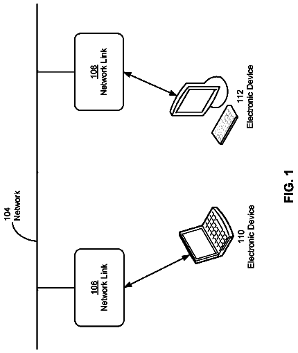
FIG. 1 is a schematic diagram of a transmission system.
FIG. 2 is a diagram illustrating a hardware structure of a transmission terminal.
FIG. 3 is a diagram illustrating a hardware structure of a management system, a relay device, a program providing system, or a maintenance system.
FIG. 4 is a functional block diagram illustrating each of a terminal, a device, and a system configuring the transmission system according to a first embodiment.
FIG. 5 is a conceptual diagram illustrating a relay device management table.
FIG. 6 is a conceptual diagram illustrating a terminal authentication management table.
FIG. 7 is a conceptual diagram illustrating a terminal management table according to the first embodiment.
FIG. 8 is a conceptual diagram illustrating a destination list management table.
FIG. 9 is a conceptual diagram illustrating a session management table.
FIG. 10 is a conceptual diagram illustrating a state modification management table.
FIG. 11 is a conceptual diagram illustrating a state modification management table.
FIG. 12 is a state transition diagram of a communication state.
FIG. 13 is a state transition diagram of a communication state.
FIG. 14 is a sequence diagram illustrating a process which manages state information indicating an operating status of each relay device.
FIG. 15 is a conceptual diagram illustrating a transmission/reception state of content data and various pieces of management information in the transmission system.
FIG. 16 is a sequence diagram illustrating a process performed in a preparatory phase before a call is initiated between transmission terminals.
FIG. 17 is a diagram illustrating a display example of a destination list.
FIG. 18 is a sequence diagram illustrating a process which makes a request to initiate a communication.
FIG. 19 is a flowchart illustrating a detailed process performed by an initiation requesting terminal in a destination selection process.
FIG. 20 is a diagram illustrating a display example of a dial confirmation dialog.
FIG. 21 is a diagram illustrating a display example of a participation authentication information entry screen.
FIG. 22 is a process flowchart illustrating a process which modifies a communication state.
FIG. 23 is a sequence diagram illustrating a process which authorizes a request to initiate a communication.
FIG. 24 is a diagram illustrating a display example of an initiation request acceptance screen.
FIG. 25 is a sequence diagram illustrating a process which makes a request to relay content data.
FIG. 26 is a process flowchart illustrating a process which modifies a communication state.
FIG. 27 is a sequence diagram illustrating a process which transmits participation requesting information for a content data session.
FIG. 28 is a diagram illustrating a display example of a destination list.
FIG. 29 is a process flowchart illustrating a process which makes determination on participation on the basis of a communication state.
FIG. 30 is a process flowchart illustrating a process which modifies a communication state.
FIG. 31 is a sequence diagram illustrating a process which makes a request to initiate a communication in a second embodiment.
FIG. 32 is a flowchart illustrating a detailed process performed by an initiation requesting terminal in a destination selection process according to the second embodiment.
FIG. 33 is a sequence diagram illustrating a process which authorizes a request to initiate a communication in a third embodiment.
FIG. 34 is a diagram illustrating an example of a destination list displayed on a display 120 of a participation requesting terminal according to the third embodiment.
FIG. 35 is a sequence diagram illustrating a process which transmits participation requesting information for a content data session according to a fourth embodiment.
FIG. 36 is a block diagram illustrating a functional structure of each of a terminal, a device, and a system configuring a transmission system 1 according to a fifth embodiment.
FIG. 37 is a diagram illustrating an example of a participation authentication information management table according to the fifth embodiment.
FIG. 38 is a diagram illustrating an example of a terminal management table according to the fourth embodiment.
FIG. 39 is a sequence diagram illustrating a process which makes a request to initiate a communication according to the fifth embodiment.
FIG. 40 is a diagram illustrating an example of a destination list displayed in a participation requesting terminal according to the fifth embodiment.
FIG. 41 is a flowchart illustrating a procedure of a participation determination process according to the fifth embodiment.
FIG. 42 is a diagram illustrating an example of a participation authentication information entry screen according to a variation.
FIG. 43 is a conceptual diagram illustrating a destination list according to another embodiment.
Description of embodiments
Embodiments of a communication system and a program will now be described in detail with reference to the attached drawings. FIG. 1 is a block diagram illustrating a configuration of a communication system and a program according to an embodiment. First Embodiment
<<Overall Configuration of Embodiment>>
Embodiments of a communication system and a program will now be described in detail with reference to FIGS. 1 to 43 . FIG. 1 is a schematic diagram of a transmission system 1 serving as a communication system according to a first embodiment and will be used to first describe an overview of the present embodiment.
The transmission system 1 includes: a data providing system which transmits content data in one direction from one transmission terminal to another transmission terminal through a management system; and a communication system which mutually communicates information and emotions among a plurality of transmission terminals through the management system. The communication system is a system in which a plurality of communication terminals (equivalent to the “transmission terminal”) communicates information and emotions with one another through a communication management system (equivalent to the “management system”), and can be a teleconference system, a videophone system, a voice conference system, a voice phone system, or a PC (Personal Computer) screen sharing system, for example.
The transmission system 1 , a management system 50 , and a transmission terminal 10 will be described in the present embodiment on the assumption that the teleconference system is given as an example of the communication system, a teleconference management system is given as an example of the communication management system, and a teleconference terminal is given as an example of the communication terminal. That is, the communication system according to the present embodiment is applied not only to the teleconference system but to the communication system and the transmission system.
The transmission system 1 illustrated in FIG. 1 includes: a plurality of transmission terminals ( 10 aa , 10 ab , etc); displays ( 120 aa , 120 ab , etc) provided for each of the transmission terminals ( 10 aa , 10 ab , etc); a plurality of relay devices ( 30 a , 30 b , 30 c , 30 d , and 30 e ); the management system 50 ; a program providing system 90 ; and a maintenance system 100 . Note that the “transmission terminal” is hereinafter simply referred to as a “terminal”, while the “management system” is simply referred to as a “management system”.
Also in the present embodiment the “transmission terminal 10 ” is used to refer to any of the transmission terminals ( 10 aa , 10 ab , etc), a “display 120 ” is used to refer to any of the displays ( 120 aa , 120 ab , etc), and a “relay device 30 ” is used to refer to any of the relay devices ( 30 a , 30 b , 30 c , 30 d , and 30 e ).
The transmission terminal 10 transmits/receives various pieces of information to/from another device. The transmission terminal 10 establishes a session with another terminal 10 , for example, and has a call therewith while transmitting/receiving content data including voice data and image data in the established session. Accordingly, a teleconference among the plurality of terminals 10 is realized in the transmission system 1 .
The “image data and the voice data” will be hereinafter referred to as the “content data”. Note that the content data transmitted among the terminals 10 is not limited to what is described in the embodiment but may be text data, for example, or content data including the text data in addition to the voice data and the image data, for example. The image data may be a moving image, a still image, or include both the moving image and the still image.
Moreover, when a teleconference is to be held in the transmission system 1 according to the present embodiment, a user who wishes to initiate the conference operates a predetermined terminal 10 , which then transmits initiation requesting information to the management system 50 .
The initiation requesting information here refers to information which makes a request to initiate a session used in the teleconference and includes information specifying the terminal 10 to be the other party in the session. The terminal 10 which transmits the initiation requesting information will be hereinafter referred to as an initiation requesting terminal. Moreover, the terminal 10 of the other party specified as the other party in the session will be referred to as a destination terminal.
The destination terminal (the other party in the session) may be one of the terminals 10 or two or more of the terminals 10 . This means that in the transmission system 1 , a teleconference can be realized by using a session established not only between two of the terminals 10 but among three or more of the terminals 10 .
Furthermore, in the transmission system 1 according to the present embodiment, another user can participate in a teleconference in the middle thereof, at which time a session has already been established and the teleconference has been initiated. A user who wishes to participate in a conference operates a predetermined terminal 10 , which then transmits to the management system 50 participation requesting information specifying the session being established (hereinafter referred to as an established session) and used in the teleconference in which the user wishes to participate. The terminal 10 which transmits the participation requesting information will be hereinafter referred to as a participation requesting terminal.
The management system 50 manages the terminal 10 and the relay device 30 in an integrated manner. The management system 50 realizes a teleconference by means of a call or a like between the terminals 10 by establishing a session between the terminals 10 .
Having received the initiation requesting information for a session from the predetermined terminal 10 , the management system 50 establishes the session between the terminal 10 (initiation requesting terminal) which has transmitted the initiation requesting information and the destination terminal, and initiates the teleconference. Having received the participation requesting information for a session which has already been established (hereinafter referred to as the established session) from the predetermined terminal 10 , on the other hand, the management system 50 determines whether or not to allow the participation requesting terminal to participate in the established session.
Furthermore, a plurality of routers ( 70 a , 70 b , 70 c , 70 d , 70 ab , and 70 cd ) illustrated in FIG. 1 selects an optimal path for the content data. Note that in the present embodiment, a “router 70 ” is used to refer to any of the routers ( 70 a , 70 b , 70 c , 70 d , 70 ab , and 70 cd ). The relay device 30 relays the content data among the plurality of terminals 10 .
The program providing system 90 includes a HD (Hard Disk) which is not shown and stores a program for terminal provided to allow the terminal 10 to implement various functions or various means, and can transmit the program for terminal to the terminal 10 . The HD in the program providing system 90 also stores a program for relay device provided to allow the relay device 30 to implement various functions or various means, whereby the program for relay device can be transmitted to the relay device 30 . Furthermore, the HD in the program providing system 90 stores a program for transmission management provided to allow the management system 50 to implement various functions or various means, whereby the program for transmission management can be transmitted to the management system 50 .
The maintenance system 100 is a computer which performs maintenance, management, or upkeep on at least one of the terminal 10 , the relay device 30 , the management system 50 , and the program providing system 90 . For example, the maintenance system 100 remotely performs maintenance, management or upkeep on at least one of the terminal 10 , the relay device 30 , the management system 50 , and the program providing system 90 through a communication network 2 when the maintenance system 100 is installed within the country while the terminal 10 , the relay device 30 , the management system 50 , or the program providing system 90 is installed outside the country. The maintenance system 100 further performs maintenance such as the management of a model number, a serial number, a sale destination, maintenance check, or a trouble history of at least one of the terminal 10 , the relay device 30 , the management system 50 , and the program providing system 90 without passing through the communication network 2 .
The terminals ( 10 aa , 10 ab , 10 ac , etc), the relay device 30 a , and the router 70 a are connected by a LAN 2 a to be able to communicate with one another. The terminals ( 10 ba , 10 bb , 10 bc , etc), the relay device 30 b , and the router 70 b are connected by a LAN 2 b to be able to communicate with one another. The LANs 2 a and 2 b are connected to be able to communicate with each other by a leased line 2 ab including the router 70 ab and are established within a predetermined region A. For example, the LAN 2 a is established at a branch in Tokyo while the LAN 2 b is established at a branch in Osaka where the region A corresponds to Japan.
On the other hand, the terminals ( 10 ca , 10 cb , 10 cc , etc), the relay device 30 c , and the router 70 c are connected by a LAN 2 c to be able to communicate with one another. The terminals ( 10 da , 10 db , 10 dc , etc), the relay device 30 d , and the router 70 d are connected by a LAN 2 d to be able to communicate with one another. The LANs 2 c and 2 d are connected to be able to communicate with each other by a leased line 2 cd including the router 70 cd and are established within a predetermined region B. For example, the LAN 2 c is established at a branch in New York while the LAN 2 d is established at a branch in Washington D.C. where the region B corresponds to the United States. The regions A and B are connected to be able to communicate with each other via Internet 2 i by the respective routers ( 70 ab and 70 cd ).
The management system 50 and the program providing system 90 are connected to the terminal 10 and the relay device 30 via the Internet 2 i to be able to communicate with one another. The management system 50 and the program providing system 90 may be installed in the region A, the region B, or another region.
The relay device 30 e is connected to the terminal 10 to be able to communicate therewith via the communication network 2 . The relay device 30 e is running at all times and thus installed in a region other than the region A or the region B in order to not be easily influenced by the traffic within a local area in the region A or B. Accordingly, the relay device 30 e is used as a relay device which relays the content data when the terminal 10 calls a terminal installed in another local area. The relay device 30 e is also used as an emergency relay device when a call is made between the terminals in the same local area in a case where the relay device installed in the local area is not running.
Note that the communication network 2 in the present embodiment is constructed by the LAN 2 a , the LAN 2 b , the leased line 2 ab , the Internet 2 i , the leased line 2 cd , the LAN 2 c , and the LAN 2 d . In addition to the wire communication provided, the communication network 2 may have an area where wireless communication is provided.
As illustrated in FIG. 1 , a set of four numbers at the bottom of each terminal 10 , each relay device 30 , the management system 50 , each router 70 , the program providing system 90 and the maintenance system 100 indicates a simplified IP address of a general IPv4. The IP address of the terminal 10 aa is “1.2.1.3”, for example. While IPv6 may be used instead of the IPv4, the IPv4 will be used to simplify the description.
<<Hardware Structure of Embodiment>>
The hardware structure of the present embodiment will now be described. FIG. 2 is a diagram illustrating a hardware structure of the terminal 10 according to the present embodiment. As illustrated in FIG. 2 , the terminal 10 according to the present embodiment includes: a CPU (Central Processing Unit) 101 which controls the overall operation of the terminal 10 ; a ROM (Read Only Memory) 102 in which the program for terminal is stored; a RAM (Random Access Memory) 103 which is used as a work area for the CPU 101 ; a flash memory 104 which stores various data such as the image data and the voice data; an SSD (Solid State Drive) 105 which controls reading or writing of the various data from/to the flash memory 104 under control of the CPU 101 ; a media drive 107 which controls reading or writing (storing) of data from/to a recording medium 106 such as a flash memory; an operation button 108 which is operated when selecting the destination terminal 10 or the like; a power switch 109 which switches a power source of the terminal 10 ON and OFF; and a network I/F (Interface) 111 which transmits data by using the communication network 2 to be described.
The terminal 10 further includes: a built-in camera 112 which captures an image of an object under control of the CPU 101 and obtains the image data; an image capturing element I/F 113 which controls drive of the camera 112 ; a built-in microphone 114 into which voice is input; a built-in speaker 115 which outputs the voice; a voice input/output I/F 116 which processes input/output of a voice signal between the microphone 114 and the speaker 115 under control of the CPU 101 ; a display I/F 117 which transmits the image data to the external display 120 under control of the CPU 101 ; an external device connecting I/F 118 which connects various external devices; an alarm lamp 119 which notifies of abnormality in various functions of the terminal 10 ; and a bus line 110 such as an address bus or a data bus which electrically connects each of the components as illustrated in FIG. 2 .
The display 120 is a display unit which is formed of a liquid crystal or organic EL and on which an image of an object or an operation icon is displayed. The display 120 is connected to the display I/F 117 by a cable 120 c . The cable 120 c may be a cable adapted for an analog RGB (VGA) signal, component video, or an HDMI (High-Definition Multimedia Interface) or DVI (Digital Video Interactive) signal.
The camera 112 includes a lens and a solid image capturing element which converts light into an electrical charge to turn the image (video) of an object into an electronic form, where the solid image capturing element is formed of a CMOS (Complementary Metal Oxide Semiconductor) or a CCD (Charge Coupled Device), for example.
The external device connecting I/F 118 can electrically connect thereto an external device such as an external camera, an external microphone, or an external speaker by a USB (Universal Serial Bus) cable or the like. The external camera, when connected, is given priority over the built-in camera 112 and driven under control of the CPU 101 . Likewise, the external microphone or the external speaker, when connected, is given priority over the built-in microphone 114 or the built-in speaker 115 , respectively, and driven under control of the CPU 101 . Note that the terminal 10 may be a general-purpose PC (Personal Computer), a smartphone, a tablet terminal, or a mobile phone. In this case, the camera 112 and the microphone 114 need not be built in but may be mounted externally.
The recording medium 106 is removable from the terminal 10 . Moreover, the flash memory 104 may be replaced by an EEPROM (Electrically Erasable and Programmable ROM) or the like as long as it is a nonvolatile memory which reads or writes data under control of the CPU 101 .
Furthermore, the program for terminal may be distributed while recorded in a recording medium (such as the recording medium 106 ) that can be read by a computer, the program having an installable or executable file format. The program for terminal may be stored not in the flash memory 104 but the ROM 102 instead.
FIG. 3 is a diagram illustrating a hardware structure of the management system according to the present embodiment. The management system 50 includes: a CPU 201 which controls the overall operation of the management system 50 ; a ROM 202 in which the program for transmission management is stored; a RAM 203 which is used as a work area for the CPU 201 ; an HD (Hard Disk) 204 in which various data is stored; an HDD (Hard Disk Drive) 205 which controls reading or writing of various data from/to the HD 204 under control of the CPU 201 ; a media drive 207 which controls reading or writing (storing) of data from/to a recording medium 206 such as a flash memory; a display 208 which displays various information such as a cursor, a menu, a window, a letter, or an image; a network I/F 209 which transmits data by using the communication network 2 to be described; a keyboard 211 which includes a plurality of keys to input a letter, a numerical value, various instructions and the like; a mouse 212 which selects and executes the various instructions, selects an object to be processed, and moves the cursor; a CD-ROM drive 214 which controls reading or writing of data from/to a CD-ROM (Compact Disc Read Only Memory) 213 as an example of a removable recording medium; and a bus line 210 such as an address bus or a data bus which electrically connects each of the components as illustrated in FIG. 3 .
Note that the program for transmission management may be distributed while recorded in a recording medium such as the recording medium 206 or the CD-ROM 213 that can be read by a computer, the program having an installable or executable file format.
The description of the relay device 30 will be omitted since the hardware structure thereof is similar to that of the management system 50 . Here, a program for relay device provided to control the relay device 30 is recorded in the ROM 202 . In this case as well, the program for relay device may be distributed while recorded in a recording medium such as the recording medium 206 or the CD-ROM 213 that can be read by a computer, the program having an installable or executable file format.
Furthermore, the description of the program providing system 90 will be omitted since the hardware structure thereof is similar to that of the management system 50 . A program for providing program which is provided to control the program providing system 90 is however recorded in the ROM 202 . In this case as well, the program for providing program may be distributed while recorded in a recording medium such as the recording medium 206 or the CD-ROM 213 that can be read by a computer, the program having an installable or executable file format.
The description of the maintenance system 100 will be omitted since the hardware structure thereof is similar to that of the management system 50 . A program for maintenance provided to control the maintenance system 100 is however recorded in the ROM 202 . In this case as well, the program for maintenance may be distributed while recorded in a recording medium such as the recording medium 206 or the CD-ROM 213 that can be read by a computer, the program having an installable or executable file format.
Note that the aforementioned programs may be provided while recorded in a recording medium such as a CD-R (Compact Disc Recordable), a DVD (Digital Versatile Disk), or a Blu-ray disk that can be read by a computer as another example of the removable recording medium.
<<Functional Structure of Present Embodiment>>
The functional structure of the present embodiment will now be described. FIG. 4 is a functional block diagram illustrating the functional structure of each of the terminals, the device and the system included in the transmission system 1 according to the present embodiment. As illustrated in FIG. 4 , the terminal 10 , the relay device 30 and the management system 50 are connected to be able to perform data communication with one another via the communication network 2 . Here, the program providing system 90 and the maintenance system 100 illustrated in FIG. 1 are omitted from FIG. 4 since the systems are not directly relevant to teleconference communication.
<Functional Structure of Terminal>
The terminal 10 includes a transmission/reception unit 11 , an operation input acceptance unit 12 , a login request unit 13 , an image capturing unit 14 , a voice input unit 15 a , a voice output unit 15 b , a display control unit 16 , a delay detection unit 18 , a store/read process unit 19 , and a destination list creation unit 20 . Each of these units is a function or means implemented when any of the components illustrated in FIG. 2 is operated by a command from the CPU 101 according to the program stored in the ROM 102 . The terminal 10 further includes a volatile memory unit 1002 constructed by the RAM 103 illustrated in FIG. 2 and a nonvolatile memory unit 1000 constructed by the flash memory 104 illustrated in FIG. 2 .
<Each Functional Unit of Terminal>
Each unit of the terminal will now be described in detail. The transmission/reception unit 11 of the terminal 10 is implemented by the network I/F 111 illustrated in FIG. 2 and transmits/receives various data (or information) to/from another terminal, device or system via the communication network 2 .
The transmission/reception unit 11 starts receiving from the management system 50 each state information representing the state of each terminal 10 as a destination terminal candidate before the concerned terminal 10 establishes a session with another terminal 10 and initiates a teleconference by placing a call.
The destination terminal candidate here refers to the terminal 10 that can be designated as the other party the concerned terminal 10 holds the teleconference with, or the other party in the session. In other words, the concerned terminal 10 cannot establish the session or hold the teleconference with a terminal that is not preset as the destination terminal candidate. The destination terminal candidate is a candidate for a partner terminal, namely a partner terminal candidate, which holds the teleconference with the concerned terminal.
The state information represents an operating status (an ON line or OFF line state) of each terminal 10 and, when the terminal is ON line, a detailed state (hereinafter referred to as a communication state) indicating whether the terminal is in call or on standby. The state information represents not only the operating status and the communication state of each terminal 10 but also a variety of states including a state where a cable is detached from the terminal 10 , voice can be output but an image cannot, or the terminal is set to not output voice (MUTE). Described below is a case where the state information represents the operating status and the communication state.
The transmission/reception unit 11 further transmits the initiation requesting information to the management system 50 when the concerned terminal 10 operates as an initiation requesting terminal. Here, the initiation requesting information refers to information which makes a request to initiate a session used in the teleconference. The initiation requesting information specifically includes the information indicating the request to initiate the session, a terminal ID of the initiation requesting terminal from which the initiation requesting information is transmitted, a terminal ID which identifies the destination terminal to be the other party in the session, and restriction information indicating whether or not participation to the session by a terminal other than the destination terminal is restricted. Note that the terminal ID is a piece of information which identifies the terminal 10 or a user thereof, and may be stored in the terminal 10 in advance or input directly into the terminal 10 by the user.
The initiation requesting information specifically includes “Invite” or “Private Invite”. Here, the “Invite” is the information which makes the request to initiate the session and, at the same time, is the restriction information indicating that participation is not restricted. On the other hand, the “Private Invite” is the information which makes the request to initiate the session and, at the same time, is the restriction information indicating that participation is restricted.
The restriction information is now described in detail. In the transmission system 1 according to the present embodiment, another terminal 10 can participate in the session that has already been established. There is however a conference such as a conference with high confidentiality where it is desired not to allow the other terminal 10 to participate. Now, in the transmission system 1 according to the present embodiment, the participation to the established session by the other terminal 10 is restricted in accordance with the restriction information indicating whether or not participation is restricted.
The transmission/reception unit 11 further transmits the participation requesting information to the management system 50 when the concerned terminal 10 operates as a participation requesting terminal. Here, the participation requesting information refers to information which makes a request for the participation to the established session used in the teleconference that has already been initiated. The participation requesting information specifically includes information “Call” indicating that it is the participation requesting information, a terminal ID of the participation requesting terminal from which the participation requesting information is transmitted, and a terminal ID of a participant terminal that is a terminal already participating in the established session in which the participation requesting terminal wishes to participate. Here, the participant terminal specifically refers to the initiation requesting terminal or the destination terminal which is indicated in the initiation requesting information transmitted when starting the established session. The transmission/reception unit 11 here functions as an initiation requesting information acquisition unit which acquires the initiation requesting information and a participation requesting information acquisition unit which acquires the participation requesting information.
The operation input acceptance unit 12 is implemented by the operation button 108 and the power switch 109 illustrated in FIG. 2 and accepts various inputs from a user. Once the user has turned on the power switch 109 illustrated in FIG. 2 , for example, the operation input acceptance unit 12 illustrated in FIG. 4 accepts the power-on input and thus turns on the power source.
The login request unit 13 is implemented by a command from the CPU 101 illustrated in FIG. 2 , triggered by the acceptance of the power-on input, and automatically transmits login requesting information indicating a request to login as well as a current IP address of the concerned terminal 10 to the management system 50 from the transmission/reception unit 11 via the communication network 2 . Once the user has turned off the power switch 109 from the on state, the transmission/reception unit 11 transmits state information indicating that the power source is turned off to the management system 50 , followed by the operation input acceptance unit 12 completely turning off the power source. The management system 50 can therefore figure out that the power source of the terminal 10 has been turned off from the on state.
The description continues in the full USPTO document.
 Lapsed, fee not paid3 drawings