Field
Embodiments described herein generally relate to semiconductor packages, and specially, to methods, systems, and apparatuses for cooling semiconductor packages.
Background
One type of semiconductor package is a multi-chip semiconductor package or multi-chip package (MCP), which is an electronic package with multiple components—e.g., integrated circuits (ICs), semiconductor dies or other discrete components—that are packaged onto a substrate. MCPs can be formed using three-dimensional (3D) packaging technologies that exploit the z-height dimension by stacking semiconductor dies in a vertical configuration to make the resultant MCP footprint in the x-y dimensions smaller. Examples of packages created by 3D packaging technologies include package-on-package (PoP) solutions, package-in-package (PiP) solutions, embedded wafer level (eWLB) packages, etc.
Integrated heat spreader (IHS) solutions can be used in MCPs to dissipate unwanted heat produced by the components of MCPs. One disadvantage of stacking dies in an MCP is that the z-height of components in the MCP can vary, which can have negative effects on the performance capabilities of the MCP by increasing unwanted heat production. Typical integrated heat spreader (IHS) solutions do not work as effectively because of these variations in component height. FIGS. 1A-1B illustrate this issue.
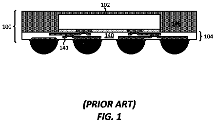
FIG. 1A is a cross-sectional view of a typical MCP 100 that includes a typical IHS solution. As shown in FIG. 1A , components 103 and 104 , each of which can include semiconductor die(s), are on a substrate 101 . In the MCP 100 , a typical IHS solution is used for dissipation of unwanted heat produced by the components 103 and 104 . This typical IHS solution includes a typical IHS lid 102 , a first thermal interface material layer (TIM-1 layer) 105 on the component 104 , and a TIM-1 layer 106 on the component 103 . Sidewall regions of the typical IHS lid 102 are attached to the substrate 101 using a sealant (not shown), such that the typical IHS lid 102 is over the components 103 and 104 . The TIM-1 layers 105 and 106 couple the components 104 and 103 , respectively, to a central region of the typical IHS lid 102 thermally and/or mechanically.
The components 103 and 104 have varying z-heights from each other, which are collectively referred to as a height variation. Specifically, this height variation occurs because the component 104 has a larger z-height than the component 103 . This height variation can include a natural height variation inherent in the manufacturing processes used to create components 103 and 104 . This natural height variation can occur regardless of whether the manufacturing process used to manufacture the component 103 is the same as or different from the manufacturing process used to manufacture the component 104 . Another contributor to the height variation affecting the components 103 and 104 can result from attachment mechanisms or techniques used to attach components 103 and 104 to the substrate 101 . For example, if the component 103 represents a die mounted on a substrate 101 via a ball grid array (BGA) assembly (not shown), while the component 104 represents a die directly attached to substrate 101 , then there can be some differences between the z-height of the components 103 and the component 104 .
In addition to their heat dissipation functions, the TIM-1 layer 105 and TIM-1 layer 106 are used to compensate for this height variation. As shown in FIG. 1A , TIM-1 layer 106 is thicker than TIM-1 layer 105 to compensate for the component height difference. Compensating for the height variation affecting the components 103 and 104 occurs at the expense of increasing the z-height or bond line thickness (BLT) of the TIM-1 layers 106 and 105 . Thicker BLTs of the TIM-1 layers 106 and 105 , however, reduce the cooling capabilities of the TIM-1 layers 106 and 105 , which in turn leads to higher chip junction temperature (T.sub.j), limited bandwidth, frequency, greater power leakage, and the like. Additionally, absorption of the height variation by the TIM-1 layers 105 and 106 can limit choices of TIM-1 materials used for forming the TIM-1 layers 105 and 106 .
Currently, an architectural IHS solution in the form of a typical three-dimensional IHS solution (typical 3D IHS solution) can avoid increasing the BLTs of the TIM-1 layers. Nevertheless, this typical 3D IHS solution fails to remedy the shortcomings of the typical IHS solution described above in connection with FIG. 1A .
FIG. 1B is a cross-sectional view of a typical MCP 150 having a typical 3D IHS solution for dissipating heat produced by the components 123 and 124 . This typical 3D IHS solution includes a typical IHS lid 122 , a TIM-1 layer 126 on the component 123 , a TIM-1 layer 125 on the component 124 , a copper (Cu) foil 127 on the TIM-1 layer 126 , a Cu foil 131 on the TIM-1 layer 125 , an intermediate thermal interface material layer (TIM-1A layer) 129 on the Cu foil 127 , and a TIM-1A layer 133 on the Cu foil 131 . In FIG. 1B , the Cu foils 127 and 131 are coupled to the typical IHS lid 122 using TIM-1A layers 129 and 133 , respectively. Each respective combination of a Cu foil and a TIM-1A layer acts as an individual IHS solution for its respective component. The BLT of the TIM-1 layer 126 is substantially equal to the BLT of the TIM-1 layer 125 . Moreover, the z-height of the Cu foil 127 is substantially equal to the z-height of the Cu foil 131 . Consequently, the height variation affecting the components 123 and 124 is absorbed by the TIM-1A layers 129 and 133 , respectively. As shown in FIG. 1B , the BLT of the TIM-1A layer 129 is larger than the BLT of the TIM-1A layer 133 . Thus, the height variation affecting the components 123 and 124 is transferred from the TIM-1 layers 126 and 125 to the TIM-1A layers 129 and 133 , respectively. Increases in the BLTs of the TIM-1A layers 129 and 133 result in reductions to their cooling capabilities. Consequently, the typical 3D IHS solution merely transfers the problem associated with BLTs of the TIM-1 layers to the BLTs of the TIM-1A layers.
Furthermore, the Cu foils 127 and 131 generally need to be several times larger in the x-y dimensions than the components 123 and 124 . Thus, the typical 3D IHS solution is limited because it needs keep-out zones with large x-y dimensions to dissipate unwanted heat.
Brief description of the drawings
Embodiments described herein are illustrated by way of example and not limitation in the figures of the accompanying drawings, in which like references indicate similar features. Furthermore, in the figures, some conventional details have been omitted so as not to obscure from the inventive concepts described herein.
FIG. 1A is a cross-sectional view of a typical MCP that includes a typical integrated heat spreader (IHS) solution.
FIG. 1B is a cross-sectional view of a typical MCP that includes a typical three-dimensional (3D) IHS solution.
FIGS. 2A-2B illustrate cross-section side views of a smart IHS lid, in accordance with at least one embodiment.
FIG. 2C illustrates a cross-section side view of a semiconductor package including a multi-reference integrated heat spreader (IHS) solution or a smart IHS solution, in accordance with an embodiment.
FIG. 2D illustrates a cross-section side view of a semiconductor package including a smart IHS solution, in accordance with another embodiment.
FIG. 2E illustrates a cross-section side view of a semiconductor package including a smart IHS solution and a heat sink, in accordance with at least one embodiment.
FIG. 3 is a process flow illustration of a method of forming a smart IHS lid, in accordance with one embodiment.
FIG. 4 is a process flow illustration of a method of forming a semiconductor package that includes a smart IHS solution, in accordance with one embodiment.
FIGS. 5A-5G are cross-sectional side view illustrations of a method of forming a semiconductor package that includes a smart IHS solution in accordance with an embodiment.
FIGS. 6A-6G are cross-sectional side view illustrations of a method of forming a semiconductor package that includes a smart IHS solution in accordance with another embodiment.
FIG. 7 is a process flow illustration of a method of forming a semiconductor package that includes a smart IHS solution, in accordance with another embodiment.
FIG. 8 is an illustration of a schematic block diagram of a computer system that utilizes a semiconductor package that includes a smart IHS solution, according to an embodiment.
Detailed description
Embodiments described herein provide methods, systems, and apparatuses that can assist with improving integrated heat spreader (IHS) solutions for semiconductor packages, such as multi-chip packages (MCPs).
For one aspect, embodiments integrate a multi-reference integrated heat spreader (IHS) solution or a smart IHS solution into an MCP to improve heat dissipation of unwanted heat produced by one or more components of an MCP.
For one embodiment, a “multi-reference integrated heat spreader solution,” a “multi-reference IHS solution,” a “smart integrated heat spreader solution,” a “smart IHS solution,” and their variations refer to an architectural solution that includes each of the following components: (i) a smart IHS lid formed from a thermally conductive material, where the smart IHS lid has at least one cavity formed in a central region of the smart IHS lid; (ii) at least one TIM-layer 1 to be on at least one component of a semiconductor package (e.g., an MCP, etc.); (iii) at least one individual IHS lid (IHS slug) formed from a thermally conductive material to be on the at least one TIM-1 layer and inserted into the at least one cavity of the smart IHS lid; and (iv) at least one TIM-1A layer to be on the at least one IHS slug and/or layered in the at least one cavity of the smart IHS lid. For an alternate embodiment, the smart IHS solution includes at least one of the components described above. For one embodiment, the smart IHS solution is a heat exchanger that transfers heat from a heat source (e.g., one or more components of a semiconductor package (e.g., an MCP, etc.)) to a secondary heat exchanger (e.g., a heat sink, an ambient environment, etc.). For one embodiment, sidewalls of a cavity formed in the smart IHS lid surround sidewalls of an IHS slug on a TIM-1 layer such that at least one portion of the IHS slug is inserted in the cavity. Furthermore, and for one embodiment of a smart IHS solution, a TIM-1A layer is between a cavity of the smart IHS lid and an IHS slug inserted into the cavity.
Use of a smart IHS solution can assist with dissipation of unwanted heat produced by one or more components of a semiconductor package (e.g., an MCP, etc.) in the following ways: (i) the IHS slugs can assist with mitigating the impact of power non-uniformity affecting the components of the package; (ii) the use of a TIM-1A layer between at least one cavity of the smart IHS lid and at least one IHS slug can assist with coupling heat from the IHS slug through the TIM-1A-layer, which can in turn increase the area of heat transfer; (iii) the combination of the smart IHS lid and at least one IHS slug can be designed to have a minimum overlap area and thermal performance, which can effectively mitigate bond line thickness (BLT) variation; (iv) the smart IHS solution may be able to assist with increasing performance of a semiconductor package (e.g., an MCP, etc.) (as compared with the typical IHS solutions described above in connection with FIGS. 1A-1B ); (v) the smart IHS solution can be used with dense package architectures that require tight pitches between package components; (v) the smart IHS solution can be used with currently available manufacturing techniques, which can assist with reducing manufacturing costs; and (vii) the smart IHS solution can leverage current and/or future improvements in materials because the smart IHS solution is an architectural solution (as opposed to a material-based solution).
For one embodiment, a semiconductor package includes a component on a substrate. For one embodiment, the package includes at least one semiconductor die and a smart integrated heat spreader (IHS) solution. For a further embodiment, the smart IHS solution includes a smart IHS lid. For one embodiment, the smart IHS lid includes a cavity formed in a central region of the smart lid. For one embodiment, the smart IHS lid is on the component, such that the cavity corresponds to the component. For one embodiment, the smart IHS solution also includes a first thermal interface material layer (TIM-layer 1) on the component. For a further embodiment, the smart IHS solution also includes an individual IHS lid (IHS slug) on the TIM-1 layer. For an even further embodiment, the IHS slug is inserted into the cavity of the smart IHS lid, where sidewalls of the cavity surround at least some portion of the sidewalls of the IHS slug. For one embodiment, the smart IHS solution includes an intermediate thermal interface material layer (TIM-1A layer) that is between the IHS slug and cavity of the smart IHS lid.
For one embodiment, the TIM-1A layer is formed in the cavity of the smart IHS solution before the IHS slug is inserted into the cavity of the smart IHS lid. For an alternate embodiment, the TIM-1A layer is on IHS slug before the IHS slug is inserted in the cavity of the smart IHS lid. The TIM-1A layer can include least one of a polymeric thermal interface material (PTIM), an epoxy, a liquid phase sintering (LPS) paste, or a solder paste. For one embodiment, the smart IHS lid is coupled to the IHS slug. For example, the smart IHS lid is at least one of thermally coupled or mechanically coupled to the IHS slug. In addition, the smart IHS lid can be mechanically coupled to the substrate with a sealant.
The package can include a heat sink on the smart IHS lid, where the heat sink is coupled to the smart IHS lid with a second thermal interface material (TIM-2) layer on the smart IHS lid between the heat sink and the smart IHS lid. For example, the heat sink is at least one of thermally coupled or mechanically coupled to the smart IHS lid.
FIGS. 2A-2B illustrate cross-section side views of a smart IHS lid 202 , in accordance with at least one embodiment. Referring to FIG. 2A , which shows the smart IHS lid 202 with at least one cavity formed in a central region of the smart IHS lid 202 . For the specific embodiment illustrated in FIG. 2A , the smart IHS lid 202 includes two cavities 207 and 209 formed in a central region of the smart IHS lid 202 . It is to be appreciated that embodiments of the smart IHS lid described herein can include one or more cavities—e.g., the smart IHS lid 232 described below in connection with FIG. 2D includes only one cavity.
The smart IHS lid 202 can be formed from a thermally conductive material, such as metal. For example, the smart IHS lid 202 can be formed from at least one of copper, aluminum, steel, nickel, any other metal, a metal alloy, any other conductive material, or any combination thereof. Each of the cavities 207 and 209 can be formed using techniques known in the art. For example, forming the cavities 207 and 209 includes mechanically cutting the cavities using at least one of laser drilling, etching, forging, stamping, or die-casting as known in the art. Each of the cavities 207 and 209 can have a square, rectangular, round, oval, or any other shape that corresponds to an underlying component of a semiconductor package (not shown in FIGS. 2A-2B ). For each of the cavities 207 and 209 in the smart IHS lid 202 , its size is greater than a size of an underlying component of a semiconductor package (e.g., an MCP, etc.) (not shown in FIGS. 2A-2B ). For some embodiments, a z-height of each of the cavities 207 and 209 is less than or equal to 2000 μm. For one embodiment, a width and a length (i.e., the x-y dimensions) of each of the cavities 207 and 209 are greater than a width and a length of an underlying component of a semiconductor package (e.g., an MCP, etc.) (not shown in FIGS. 2A-2B ). For one embodiment, each of the cavities 207 and 209 in the smart IHS lid 202 is centered over the component. For a further embodiment, the thickness of the smart IHS lid 202 is greater than the heights of each of the cavities 207 and 209 . For some embodiments, the thickness of the smart IHS solution is greater than 2000 μm.
Referring to FIG. 2B , the cavity 207 includes an intermediate level thermal interface material (TIM-1A) layer 211 formed on each wall of the cavity 207 and the cavity 209 includes a TIM-1A layer 213 formed on each wall of the cavity 209 . For some embodiments, the layering of the cavities 207 and 209 of the smart IHS lid 202 with the TIM-1A layers 211 and 213 , respectively, can assist with dissipating heat from components of semiconductor package (not shown in FIGS. 2A-2B ), which can in turn assist with increasing the area of heat transfer to maximize heat dissipation from the semiconductor package. As shown in FIG. 2B , a top wall of the cavity 207 that is parallel (or co-planar) with a top of the smart IHS lid 202 has a TIM-1A layer 211 with a z-height that ranges between 50 μm and 450 μm. Moreover, a top wall of the cavity 209 that is parallel (or co-planar) with a top of the smart IHS lid 202 has a TIM-1A layer 213 with a z-height that ranges between 50 μm and 450 μm. For one embodiment, a thickness or bond line thickness (BLT) of the TIM-1A layer 211 can be different from a thickness or BLT of the TIM-1A layer 213 . For another embodiment, a thickness or BLT of the TIM-1A layer 211 can be equal or substantially equal to a thickness or BLT of the TIM-1A layer 213 .
For one embodiment, the TIM-1A layers 211 and 213 are deposited into the respective cavities 207 and 209 . For this embodiment, the deposited TIM-1A layers 211 and 213 are cured and/or baked to adhere the TIM-1A layers 211 and 213 to the walls of the cavities 207 and 209 . For an alternate embodiment, the TIM-1A layers 211 and 213 are each deposited into the respective cavities 207 and 209 without curing and/or baking. For this alternate embodiment, the TIM-1A layers 211 and 213 adhere to the walls of the cavities 207 and 209 due to the properties (e.g., chemical properties, mechanical properties, magnetic properties, etc.) of the TIM(s) used for forming the TIM-1A layers 211 and 213 .
For one embodiment, each TIM used for forming the TIM-1A layers 211 and 213 is a material that exhibits high thermal conductivity—for example, copper, silver, gold, beryllium oxide, aluminum, tungsten, zinc, brass, and any other material or combination of materials known in the art to exhibit high thermal conductivity. For one embodiment, the thermal conductivity of each of TIM-1A layers 211 and 213 ranges from 2 watts per meter kelvin (W/mK) to 30 W/mK. For a further embodiment, each of the TIM-1A layers 211 and 213 includes at least one of a polymeric thermal interface material (PTIM) with a thermal conductivity that ranges from 2 W/mK to 7 W/mK, an epoxy with a thermal conductivity that ranges from 10 W/mK to 20 W/mK, a liquid phase sintering (LPS) paste with a thermal conductivity that ranges from 5 W/mK to 15 W/mK, or a solder paste with a thermal conductivity that ranges from 10 W/mK to 30 W/mK.
FIG. 2C illustrates a cross-section side view of a semiconductor package 200 including a smart IHS solution, in accordance with at least one embodiment. The package 200 can be a multi-chip package (MCP). It is to be appreciated that the package 200 does not have to be a MCP package—for example, the package 200 can be a single-chip package. The smart IHS lid 202 described below in connection with FIG. 2C is similar to or the same as the smart IHS lid 202 described above in connection with at least one of FIGS. 2A-2B .
Referring to FIG. 2C , one embodiment of the package 200 includes the following: (i) a substrate 201 ; (ii) a component 203 ; (iii) a component 204 ; (iv) a first level thermal interface material (TIM-1) layer 205 on the component 204 ; (v) a TIM-1 layer 206 on the component 203 ; (vi) a smart IHS lid 202 that includes cavities 207 and 209 ; (vii) an individual IHS lid (IHS slug) 297 on the TIM-1 layer 206 ; (viii) an IHS slug 299 on the TIM-1 layer 205 ; (ix) an intermediate level thermal interface material (TIM-1A) layer 211 between the cavity 207 and the IHS slug 297 ; (x) a TIM-1A layer 213 between the cavity 209 and the IHS slug 299 ; and (xi) a sealant 217 .
As shown in FIG. 2C , the package 200 can include multiple components, such as the components 203 and 204 , on a substrate 201 . The components 203 and 204 can be adjacent to each other and can be spaced apart from each other on substrate 201 . The components 203 and 204 can be any one of active and passive electronic device components—e.g., transistors, memories, capacitors, resistors, optoelectronic devices, switches, interconnects, and any other electronic device components. For one embodiment, at least one of the components 203 and 204 includes a memory, a processor, a Platform Controller Hub (PCH), a Peripheral Component Interconnect (PCI), a Graphics Processing Unit (GPU), an on-chip system fabric, a network interface controller, a stacked component, a non-stacked component, a ball grid array (BGA) package, any other electronic component, or any combination thereof.
The components 203 and 204 can have different z-heights relative to the surface of the substrate 201 . For one embodiment, the z-height of the components 203 and 204 on the substrate 201 is from 400 μm to 1170 μm. For a specific embodiment, the components 203 and 204 each include at least one die that has a z-height of at least 770 μm. For one embodiment, a height difference between the components 203 and 204 is at least 400 μm. The height variation affecting the components 203 and 204 can be attributable to one or more causes, as described above in connection with FIGS. 1A-1B .
For one embodiment, the components 203 and 204 include a semiconductor die. For some embodiments, at least one of the components 203 and 204 is a non-stacked die component. For other embodiment, at least one of the components 203 and 204 is a stacked die component. For some embodiments, at least one of the components 203 and 204 is a die block. Each die block can be a stacked die package or non-stacked die package. For one embodiment, the components 203 and 204 are manufactured using the same or similar manufacturing processes. For one embodiment, the components 203 and 204 are manufactured using different manufacturing processes. For one embodiment, the components 203 and 204 are similar to or the same as each other—e.g., each of components 203 and 204 is a die that is directly attached to the substrate 201 . For an alternate embodiment, the components 203 and 204 are different from each other—e.g., the component 203 can be a non-stacked die package, while the component 204 is a stacked die package. For some embodiments, at least one of the components 203 and 204 is attached to the substrate 201 via any attachment mechanisms or techniques known in the art—e.g., a BGA substrate.
Although FIG. 2C illustrates the package 200 as having only two components (i.e., the components 203 and 204 ), the number of components on the package 200 can be at least one component. Generally, a die in the context of integrated circuits is a small block of semiconducting material, on which a functional circuit is fabricated. Typically, integrated circuits are produced on a wafer of electronic-grade silicon or other semiconductor, for example, Gallium Arsenide (“GaAs”) using one of photolithography techniques known in the art.
The wafer is typically cut (“diced”) into many pieces, each containing a copy of the circuit. Each of these pieces can be called a die or a chip. The die can be mounted on a substrate, such as substrate 201 , using different techniques known in the art. For example, mounting die on the substrate 201 can be performed using wire bonding, a flip-chip connection, and any other technique known in the art. The die can be directly attached to the substrate using any technique known in the art. For one embodiment, the substrate 201 is a laminated substrate at a bottom side of an electronic device package. The substrate 201 can have conductive traces that route and connect, for example, the die-to-substrate bonds to the substrate-to-ball array bonds.
For one embodiment, the substrate 201 includes an organic core, resin, filler material, copper, solder epoxy underfill, solder, or a combination thereof. For some embodiments, the substrate 201 is a ceramic substrate. For other embodiments, the substrate 201 includes a semiconductor material—for example, monocrystalline silicon (“Si”), germanium (“Ge”), silicon germanium (“SiGe”), a III-V material (such as gallium arsenide (“GaAs”)), or any combination thereof. For one embodiment, the substrate 201 includes metallization interconnect layers for integrated circuits. The substrate 201 can include electronic devices—for example, transistors, memories, capacitors, resistors, optoelectronic devices, switches, and any other active and passive electronic devices that are separated by an electrically insulating layer. The insulating layer can be an interlayer dielectric, a trench insulation layer, or any other insulating layer known in the art of the electronic device manufacturing. For some embodiments, the substrate 201 includes interconnects—for example, one or more vias configured to connect metallization layers.
The package 200 can include a TIM-1 layer on each of the components. Specifically, a TIM-1 layer 206 is on the component 203 and a TIM-1 layer 205 is on the component 204 . Thermal interface materials (TIMs) are used to facilitate thermal conduction from a component (e.g., components 203 and/or 204 ) to a secondary heat exchanger (e.g., a heat sink, an ambient environment, other secondary heat exchangers, etc.). TIMs can assist with minimizing interface thermal resistance. Each of the TIM-1 layers 205 and 206 can be at least one of a high thermal conductivity adhesive material or a metallic alloy. Thus, the TIMs used to form the TIM-1 layers 205 and 206 are typically high thermal conductivity materials that become liquidous or near-liquidous at predetermined operating temperatures. The TIMs can flow and fill surface asperities enabling reductions in thermal resistance between two contacting surfaces. The TIMs used to make at least one of the TIM-1 layers 205 or 206 can be at least one of a metal based TIM, a polymer matrix TIM, thermal grease, or any other TIM-1 material layer known in the art. At least one of the TIM-1 layers 205 or 206 can be a metallic alloy with a low melting point. At least one of the TIM-1 layers 205 or 206 can be a solder thermal interface material (“STIM”), such as an indium solder TIM. For one embodiment, each of the TIM-1 layers 205 and 206 is 99.99% indium solder. For one embodiment, at least one of the TIM-1 layers 205 or 206 is a metal based alloy layer. For example, one or both of the TIM-1 layers 205 and 206 includes at least one of indium, tin, lead, silver, antimony, bismuth, zinc, cadmium, gold, copper, ruthenium, nickel, cobalt, chromium, iron, manganese, titanium, aluminum, hafnium, tantalum, tungsten, vanadium, molybdenum, palladium, platinum, or any combination thereof.
For some embodiments, the TIM-1 layers 205 and 206 are deposited on the components 204 and 203 , respectively. Deposition of TIM-1 layers can be performed using any techniques known in the art. For one embodiment, a thickness or BLT of the TIM-1 layer 205 can be different from a thickness or BLT of the TIM-1 layer 206 . For another embodiment, a thickness or BLT of the TIM-1 layer 205 can be equal or substantially equal to a thickness or BLT of the TIM-1 layer 206 . For one embodiment, the TIM-1 layers 205 and 206 have a single predetermined BLT. For a further embodiment, the minimum thickness of each of the TIM-1 layers 205 and 206 is less than 50 μm. For some embodiments, the thickness of the each of the TIM-1 layers 205 and 206 is from about 20 μm to about 50 μm. For an embodiment, each of the TIM-1 layers 205 and 206 is a TIM-1 preform that has a predetermined shape adjusted to a shape of die(s) on the components 203 and 204 , respectively. The TIM-1 preform can be placed on the top surface of any one of the components 203 and 204 using, for example, a vacuum tool. The TIM-1 preform can be manufactured using one of techniques known in the art—e.g., by stamping, etc. For one embodiment, the TIM-1 preform is placed on the die using any suitable tool known in the art.
The package 200 can also include a plurality of individual IHS lids (IHS slugs) 297 and 299 on the TIM-1 layers 206 and 205 , respectively. For one embodiment, the IHS slugs 297 and 299 are deposited on the TIM-1 layers 206 and 205 , respectively. For one embodiment, a thickness of the IHS slug 297 in the z-direction can be different from a thickness of the IHS slug 299 in the z-direction. For another embodiment, a thickness of the IHS slug 297 in the z-direction can be equal or substantially equal to a thickness of the IHS slug 299 in the z-direction.
For one embodiment, the IHS slug 297 has x-y dimensions (i.e., length and width) that are at least the same as x-y dimensions (i.e., length and width) of the component 203 and the IHS slug 299 has x-y dimensions that are at least the same as x-y dimensions of the component 204 . For example, the IHS slug 297 has the same length and the same width as the component 203 , which can be a die or a die stack. For one embodiment, each of IHS slug 297 and IHS slug 299 has a height (i.e., z-height) that less than or equal to 2000 μm. For yet another embodiment, each of IHS slug 297 and IHS slug 299 has a height (i.e., z-height) that ranges from 500 μm to 2000 μm. For another embodiment, the IHS slug 297 has x-y dimensions (i.e., length and width) that are larger than the x-y dimensions (i.e., length and width) of the component 203 and the IHS slug 299 has x-y dimensions that are larger than the x-y dimensions of the component 204 .
As shown in FIG. 2C , the IHS slugs 297 and 299 are included in the package 200 to dissipate heat generated by the components 203 and 204 , respectively. This can assist with mitigating the impact of power non-uniformity in the die(s) of the component 203 and the die(s) of the component 204 . For some embodiments, each of the IHS slugs 297 and 299 is a copper plate, aluminum plate, any other plate made from a highly thermally conductive material, or a combination thereof. For some embodiments, each of the IHS slugs 297 and 299 has an area size adjusted to the size of its respective component. For example, the IHS slug 297 has a size adjusted to the size of component 203 . The IHS slugs 297 and 299 can have a square, rectangular, round, oval, or any other shape that corresponds to the underlying components 203 and 204 , respectively. Each of the IHS slugs 297 and 299 can act as a first heat exchanger that moves heat between a heat source (e.g., components 203 and 204 ) and the smart IHS lid 202 , whose larger surface area and geometry are more adapted to remove overall heat from the package 200 . The heat produced by a heat source (e.g., component 203 and 204 ) is “spread out” by the IHS slugs 297 and 299 allowing the smart IHS lid 202 to increase the heat capacity of the package 200 .
Referring still to FIG. 2C , the package 200 can also include a smart IHS lid 202 that includes the cavities 207 and 209 , where the TIM-1A layer 211 is between the cavity 207 and the IHS slug 297 and where the TIM-1A layer 213 is between the cavity 209 and the IHS slug 299 . The smart IHS lid 202 of FIG. 2C is similar to or the same as the smart 202 described above in connection with FIG. 2B . One of the advantages of the smart IHS lid 202 can be seen from a comparison of the smart IHS lid 202 with a presently available IHS lid, such as the IHS lid 102 or the IHS 122 described above in connection with FIGS. 1A-1B . Component variability in a semiconductor package can increase bond line thickness (BLT) of the TIM-1 layers used to couple a presently available IHS lid (e.g., the IHS lid 102 or the IHS lid 122 ) to components of a semiconductor package. This may cause an increase in the thermal resistance of the TIM-1 layers as the thickness of the TIM layer 116 increases. As such, a thinner TIM-1 layer, such as the TIM-1 layers 205 and 206 that have fixed z-heights, may more effectively dissipate heat from components of a semiconductor package. In addition to added thermal resistance due to additional thickness of TIM-1 layers, the variability of the required thickness of the TIM-1 layer limits the choice of materials. For instance, many pad type TIM-1 layer materials may not be sufficiently compressible to accommodate the required dimensional variability. Additionally, some thermal grease materials may lack the thermal conductivity required, particularly where the x-y dimensions require relatively thick TIM-1 layers.
One or more embodiments of the smart IHS lid 202 described herein can assist with reducing or mitigating some of the issues associated with presently available IHS lids. For one embodiment, the smart IHS lid 202 is used in combination with the IHS slugs 297 and 299 to assist with improved heat dissipation from the components 203 and 204 , when the cavities 207 and 209 of the smart IHS lid 202 are filled with the TIM-1A layers 211 and 213 . The following description explains how the smart IHS lid 202 , the IHS slugs 297 and 299 , the cavities 207 and 209 , and the TIM-1A layers 211 and 213 can be used to provide one or more of the advantages described herein. For the sake of brevity, only the IHS slug 297 , the cavity 207 , and the TIM-1A layer 211 will be described. It is to be appreciated that the following description also applies to the IHS slug 299 , the cavity 209 , and the TIM-1A layer 213 .
Referring still to FIG. 2C , the IHS slug 297 can be inserted into the cavity 207 such that the TIM-1A layer 211 encapsulates the IHS slug 297 . Stated differently, and for one embodiment, the sidewalls of the cavity 211 surround the sidewalls of the IHS slug 297 such that at least one portion of the IHS slug 297 is inserted in the cavity 207 . In this way, the cavity 207 enables existence of some overlap between the smart IHS lid 202 and the IHS slug 297 . For one embodiment, an x-dimension, a y-dimension, or a z-dimension of the cavity 207 is larger than a corresponding x-dimension, a corresponding y-dimension, or a corresponding z-dimension of the IHS slug 297 to enable the IHS slug 297 to be inserted into the cavity 207 such that the TIM-1A layer 211 encapsulates the IHS slug 297 . For a first example, the cavity 207 has x-y dimensions that are larger than x-y dimensions of the of the IHS slug 297 to enable the IHS slug 297 to be inserted into the cavity 207 such that the TIM-1A layer 211 encapsulates the IHS slug 297 . For a second example, the cavity 207 has a z-dimension that is larger than a z-dimension of the of the IHS slug 297 to enable the IHS slug 297 to be inserted into the cavity 207 such that the TIM-1A layer 211 encapsulates the IHS slug 297 .
As shown in FIG. 2C , the TIM-1A layer 211 encapsulates the IHS slug 297 . As used herein, “encapsulating” and its variations do not require all surfaces of an IHS slug to be encased within a TIM-1A layer. For one embodiment, the encapsulation of IHS slug 297 by the TIM-1A layer 211 enables heat dissipation through the TIM-1A layer 211 to be improved. Furthermore, this encapsulation can enable any variation in the z-height of component 203 to be absorbed by at least one of the IHS slug 297 or the TIM-1A layer 211 . For example, if the cavity 207 has fixed z-height of 2000 μm, the TIM-1 layer 206 has a fixed z-height of 50 μm and the component 203 has a variable z-height of 400 μm to 1170 μm, then the IHS slug 297 can have a variable z-height of 500 μm to 2000 μm or the TIM-1A layer 207 can have a variable z-height of 50 μm to 450 μm. Thus, any variations in the z-height of the component 203 can be absorbed by adjusting at least one of the z-height of IHS slug 297 or the z-height of the TIM-1A layer 211 . The overlap created by placing the IHS slug 297 inside the cavity 207 can assist with reducing at least one of the BLT of the TIM-1 layer 206 or the BLT of the TIM-1A layer 211 , which can in turn assist with minimizing interface thermal resistance, which can further assist with improving heat dissipation by the smart IHS solution shown in FIG. 2C . For one embodiment, the encapsulation of IHS slug 297 by the TIM-1A layer 211 enables any variation in the z-height of component 203 to be absorbed by the TIM-1A layer 211 without being absorbed by the IHS slug 297 . For another embodiment, the encapsulation of IHS slug 297 by the TIM-1A layer 211 enables any variation in the z-height of component 203 to be absorbed by the IHS slug 297 without being absorbed by the TIM-1A layer 211 .
For one embodiment, and with regard to FIG. 2C , when the IHS slugs 297 and 299 are transferred onto the TIM-1 layers 206 and 205 , respectively, a force is applied to ensure that the bond line thickness (BLT) of each of the TIM-1 layers 206 and 205 is minimized. This application of a force can assist with ensuring a minimum BLT of each of the TIM-1 layers 206 and 205 (which assist with making the thickness of the lower thermal conductivity TIM as low as possible and with lowering overall thermal resistance). For one embodiment, and with regard to FIG. 2C , when the smart IHS lid 202 is transferred onto the IHS slugs 297 and 299 , a force is applied to the smart IHS lid 202 to ensure that the BLT of each of the TIM-1A layers 207 and 209 is minimized. This application of a force can assist with ensuring a minimum BLT of each of the TIM-1A layers 207 and 209 (which assist with making the thickness of the lower thermal conductivity TIM as low as possible and with lowering overall thermal resistance).
The smart IHS lid 202 can be coupled to the substrate 201 via a sealant 217 . For one embodiment, the sealant 217 is dispensed at the perimeter of the smart IHS lid 202 , with a contact area limited by the area of the footprint (in the x-y dimensions) of the smart IHS lid 202 . The size of this footprint area and its location are driven by package design considerations such as, but not limited to, locations of the components 203 and 204 and the size of the substrate 201 . For some embodiments, the sealant 217 may provide some level of thermal coupling between the smart IHS lid 202 and the substrate 201 ; however, the primary purpose of the sealant 217 is to provide a structural or mechanical connection between the smart IHS lid 202 and the substrate 201 . The sealant 217 can be a seal adhesive material that is a thermally conductive material. Thermally conductive materials are known in the art. The sealant 217 can also be made from silicone- or epoxy-based sealant materials, as is known in the art. For one embodiment, clips and/or sealant-adhesives can be used as the sealant 217 to adhere the smart IHS lid 202 to the substrate 201 .
FIG. 2D illustrates a cross-section side view of a semiconductor package 225 including a smart IHS solution, in accordance with one embodiment. The package 225 shown in FIG. 2D is similar to the package 200 described above in connection with FIG. 2C . For the sake of brevity, only the differences between the package 225 and the package 200 will be described below in connection with FIG. 2D .
The description continues in the full USPTO document.
 Lapsed, fee not paid7 drawings