 Lapsed, fee not paid26 drawings
Cameras, Displays & Optics · US 9,804,523 B2
Image forming apparatus
A control portion switches first and second modes based on information which influences a toner charging amount.
US 9,804,533 B2 · Assignee: Ricoh Company, Ltd. · Inventors: Yamashita; Takeshi et al.
Sheet 1 of 9 from the published document. All sheets in the USPTO PDF
An image forming apparatus including an image bearer to bear toner; a developer bearer includes a first seal on one end of the developer bearer in a direction of axis and a second seal on another end of the developer bearer in the direction of axis, to supply the image bearer with the toner; a supply member disposed within a range between the first seal and the second seal in the direction of axis, to supply the developer bearer with the toner; and a transfer member opposed to the image bearer. The transfer member has a width shorter than a width of the supply member in the direction of axis. The transfer member is disposed within a range between one end and another end of the supply member in the direction of axis.
Technical Field Exemplary aspects of the present disclosure generally relate to an image forming apparatus, such as a copier, a facsimile machine, a printer, or a multi-functional system including a combination thereof. Related Art In an image forming apparatus that employs toner as a developer, a supply member supplies a developer bearer with toner, and the toner is then supplied onto an image bearer, developing a latent image formed on the image bearer with the supplied toner. The developed toner image is primarily transferred onto a transfer member opposed to the image bearer, and the toner image is transferred onto a recording medium conveyed by the transfer member. The developer bearer has seals on the ends of the developer bearer in the direction of axis to prevent toner from leaking out of the ends. In such a configuration, an external additive separated from toner is likely to ac
8 of 9 drawing sheets so far from the published document, cropped to the drawing. Every sheet is in the USPTO PDF.
What the patent claimed, word for word. All of it is now free to use.
This patent application is based on and claims priority pursuant to 35 U.S.C. §119(a) to Japanese Patent Application No. 2015-152592, filed on Jul. 31, 2015, in the Japan Patent Office, the entire disclosure of which is hereby incorporated by reference herein.
Technical Field
Exemplary aspects of the present disclosure generally relate to an image forming apparatus, such as a copier, a facsimile machine, a printer, or a multi-functional system including a combination thereof.
Related Art
In an image forming apparatus that employs toner as a developer, a supply member supplies a developer bearer with toner, and the toner is then supplied onto an image bearer, developing a latent image formed on the image bearer with the supplied toner. The developed toner image is primarily transferred onto a transfer member opposed to the image bearer, and the toner image is transferred onto a recording medium conveyed by the transfer member.
The developer bearer has seals on the ends of the developer bearer in the direction of axis to prevent toner from leaking out of the ends.
In such a configuration, an external additive separated from toner is likely to accumulate on the ends of the developer bearer, and the accumulated external additive is developed onto the image bearer during a developing process, resulting in the external additive aggregation (which is called as “killfish”) appearing on the image bearer. With an increase in size of the external additive aggregation, the edge of the cleaning blade may be damaged, thereby causing toner to leak out of the damaged part, contaminating a charging roller, resulting in scattering of toner because the surface of the photoconductor corresponding to a contaminated position on the charging roller is not charged while toner continues to be developed.
In an aspect of this disclosure, there is provided an image forming apparatus including an image bearer to bear toner; a developer bearer including a first seal on one end of the developer bearer in a direction of axis and a second seal on another end of the developer bearer in the direction of axis, to supply the image bearer with the toner; a supply member disposed within a range between the first seal and the second seal in the direction of axis, to supply the developer bearer with the toner; and a transfer member opposed to the image bearer. The transfer member has a width shorter than a width of the supply member in the direction of axis. The transfer member is disposed within a range between one end and another end of the supply member in the direction of axis.
The aforementioned and other aspects, features, and advantages of the present disclosure will be better understood by reference to the following detailed description when considered in connection with the accompanying drawings, wherein:
FIG. 1 is a diagram describing the relative positions of a supply member and a roller-shaped transfer member according to a first embodiment of the present disclosure;
FIG. 2 is a schematic view of a monochrome image forming apparatus according to an embodiment of the present disclosure;
FIG. 3 is a schematic view of a multi-color image forming apparatus according to another embodiment of the present disclosure;
FIGS. 4A and 4B are schematic views of surroundings of an image bearer;
FIG. 5 is a diagram describing the relative positions of a supply member and a transfer member according to a comparative example;
FIG. 6 is a diagram describing the relative positions of a supply member and a belt-shaped transfer member according to an embodiment of the present disclosure;
FIG. 7 is a diagram describing a configuration with a belt presser;
FIG. 8 is a diagram describing the relative positions of a supply member and a transfer member with the belt presser according to a second embodiment of the present disclosure; and
FIG. 9 is an enlarged view of a space between an end of the belt-shaped transfer member and an end of the supply member.
The accompanying drawings are intended to depict embodiments of the present disclosure and should not be interpreted to limit the scope thereof. The accompanying drawings are not to be considered as drawn to scale unless explicitly noted.
In describing embodiments illustrated in the drawings, specific terminology is employed for the sake of clarity. However, the disclosure of this patent specification is not intended to be limited to the specific terminology so selected and it is to be understood that each specific element includes all technical equivalents that operate in a similar manner and achieve similar results.
Although the embodiments are described with technical limitations with reference to the attached drawings, such description is not intended to limit the scope of the disclosure and all of the components or elements described in the embodiments of this disclosure are not necessarily indispensable.
Referring now to the drawings, embodiments of the present disclosure are described below. In the drawings for explaining the following embodiments, the same reference codes are allocated to elements (members or components) having the same function or shape and redundant descriptions thereof are omitted below.
Referring to FIG. 1 , a description is provided of an image forming apparatus 1 / 1 A according to an embodiment of the present disclosure. In this case, the reference number “1” denotes a monochrome image forming apparatus, and the reference number “ 1 A” denotes a color image forming apparatus. The same reference numerals will be given to constituent elements such as parts and materials having the same functions, and the descriptions thereof will be omitted. In some Figures, portions of configurations are partially omitted to better understand the configurations. It is to be noted that suffixes Y, M, C, and K denote colors yellow, magenta, cyan, and black, respectively. These suffixes may be omitted unless otherwise specified.
In the image forming apparatus 1 / 1 A according to the present embodiment, disposing a transfer member within the width of a supply member in the direction of axis prevents scattering of toner. The supply member supplies a developer bearer with toner.
A description is first provided of the entire configuration of the image forming apparatus 1 / 1 A, and then a description of configuration of characteristic portions is given.
The image forming apparatus 1 illustrated in FIG. 2 is an electrophotographic monochrome image forming apparatus 1 . In FIG. 2 , the monochrome image forming apparatus 1 includes a process cartridge 2 in the center of an apparatus body 10 . The process cartridge 2 includes a drum-shaped photoconductor 3 as an image bearer and an optical writing head 7 as an exposure unit. The photoconductor 3 rotates at a peripheral speed V 1 within a predetermined range. The optical writing head 7 forms a latent image on the photoconductor 3 . As illustrated in FIG. 4A , the process cartridge 2 includes, in a direction of rotation of the photoconductor 3 , a developing roller 23 as a developer bearer used in the electrophotographic method, a cleaning blade 25 as a cleaner that constitutes a cleaning unit, a charging roller 21 as a charger that constitutes a charging unit, and the optical writing head 7 . Between the optical writing head 7 and the photoconductor 3 , a spacer 71 is disposed to determine the distance between the photoconductor 3 and the optical writing head 7 . The developing roller 23 is supplied with toner T by a supply roller 24 as a supply member. The photoconductor 3 is supplied with toner T by the developing roller 23 . The developing roller 23 and the supply roller 24 constitute the developing unit 22 .
As illustrated in FIG. 2 , below the process cartridge 2 is a transfer roller 33 as a roller-shaped transfer member contacting the photoconductor 3 to form a transfer portion between the transfer roller 33 and the photoconductor 3 . A transfer bias is applied to the transfer roller 33 . The transfer roller 33 rotates at a peripheral speed V 2 . A difference in peripheral speed occurs between the peripheral speed V 1 of the photoconductor 3 and the peripheral speed V 2 of the transfer roller 33 . In the present embodiment, the peripheral speed V 1 is greater than the peripheral speed V 2 .
Below the transfer roller 33 , a sheet feeder 40 is disposed to include a cassette, in which recording sheets P are stacked and stored. The sheet feeder 40 feeds a recording sheet P toward the transfer portion, using a feed roller 41 . The recording sheet P fed by the sheet feeder 40 is then delivered toward the transfer portion in appropriate timing by a registration roller 42 . The registration roller 42 is disposed between the sheet feeder 40 and the transfer portion.
As illustrated in FIG. 4A , the photoconductor 3 bears a toner image on the surface 3 a of the photoconductor 3 . Such a toner image is obtained by developing a latent image written by the optical writing head 7 with the toner T supplied from the developing unit 22 . Such a toner image is then transferred onto a recording sheet P fed from the sheet feeder 40 to the transfer portion.
As illustrated in FIG. 2 , on the right side of the process cartridge 2 is disposed a fixing device 60 . The recording sheet P having the toner image transferred onto at the transfer portion is delivered to the fixing device 60 , and heat and pressure are applied to the recording sheet P. Accordingly, the toner image is melted and fixed on the recording sheet P in a fixing process. Then, the recording sheet P having the toner image fixed onto is discharged by ejection rollers 13 to a tray 14 on an upper face of the apparatus body 10 .
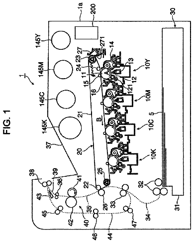
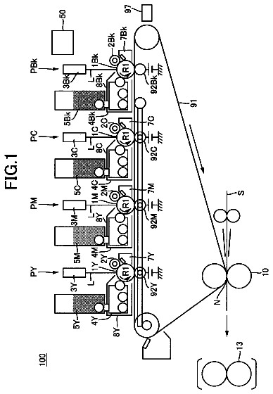
The image forming apparatus 1 A illustrated in FIG. 3 is an electrophotographic color image forming apparatus 1 A. The color image forming apparatus 1 A according to the present embodiment includes a plurality of process cartridges 2 Y, 2 M, 2 C, and 2 K for the respective colors of yellow, magenta, cyan, and black in an apparatus body 10 A. The color image forming apparatus 1 A further includes an intermediate transfer device 30 as a transfer device, a sheet feeder 40 , and a fixing device 60 . The process cartridges 2 Y, 2 M, 2 C, and 2 K include drum-shaped photoconductors 3 Y, 3 M, 3 C, and 3 K, respectively. The photoconductors 3 Y, 3 M, 3 C, and 3 K serve as image bearers. The process cartridges 2 Y, 2 M, 2 C, and 2 K further respectively include charging rollers 21 Y, 21 M, 21 C, and 21 K as chargers, each constituting a charging unit, developing units 22 Y, 22 M, 22 C, and 22 K, cleaning blades 25 Y, 25 M, 25 C, and 25 K as cleaners, each constituting a cleaning unit, and a electric charge remover. Optical writing heads 7 Y, 7 M, 7 C, and 7 K are disposed between the charging rollers 21 Y, 21 M, 21 C, and 21 K and the developing units 22 Y, 22 M, 22 C, and 22 K, respectively, as optical writing devices to scan the respective photoconductors 3 Y, 3 M, 3 C, and 3 K while emitting exposure light to the respective photoconductors 3 Y, 3 M, 3 C, and 3 K. As the optical writing device, instead of disposing the optical writing heads 7 Y, 7 M, 7 C, and 7 K in the process cartridges 2 Y, 2 M, 2 C, and 2 K, respectively, the photoconductors 3 Y, 3 M, 3 C, and 3 K may be illuminated with a plurality of exposure light beams using a polygon mirror to perform scanning.
As illustrated in FIG. 3 , the developing units 22 Y, 22 M, 22 C, and 22 K include developing rollers 23 Y, 23 M, 23 C, and 23 K as developer bearers to supply the photoconductors 3 Y, 3 M, 3 C, and 3 K with toner T, and supply rollers 24 Y, 24 M, 24 C, and 24 K as supply members to supply the developing rollers 23 Y, 23 M, 23 C, and 23 K with the toner K, respectively. The supply rollers 24 Y, 24 M, 24 C, and 24 K are collectively referred to as a supply roller 24 in some cases. The developing rollers 23 Y, 23 M, 23 C, and 23 K are collectively referred to as a developing roller 23 in some cases.
Each of the photoconductors 3 Y, 3 M, 3 C, and 3 K rotates at a peripheral speed V 1 within a predetermined range. The surfaces 3 a of the photoconductors 3 Y, 3 M, 3 C, and 3 K are uniformly charged by the charging rollers 21 Y, 21 M, 21 C, and 21 K, respectively. The charging unit may be a contact charging device that contacts each photoconductor ( 3 Y, 3 M, 3 C, and 3 K). Alternatively, a contactless charging device may be employed.
The uniformly charged surfaces 3 a of the photoconductors 3 Y, 3 M, 3 C, and 3 K are scanned by light beams projected from optical writing head 7 Y, 7 M, 7 C, and 7 K, thereby forming electrostatic latent images for the respective colors. Then, the developing rollers 23 Y, 23 M 23 C, and 23 K of the developing units 22 Y, 22 M, 22 C, and 22 K supply the photoconductors 3 Y, 3 M, 3 C, and 3 K toner T for the respective colors, developing the latent images into toner images for the respective colors.
As illustrated in FIG. 3 , an intermediate transfer device 30 includes a transfer belt 34 as a transfer member formed into an endless looped belt wound around and stretched taut about a drive roller 31 and a tension roller 32 . The transfer belt 34 rotates in a direction of rotation indicated by arrow A in FIG. 3 . Inside the loop of the transfer belt 34 , primary transfer roller 33 Y, 33 M, 33 C, and 33 K as a plurality of transfer rotators, and a cleaning roller 38 are disposed.
The primary transfer rollers 33 Y, 33 M, 33 C, and 33 K are pressed against the inner surface of the transfer belt 34 . The surfaces 3 a of the photoconductors 3 Y, 3 M, 3 C, and 3 K opposed to the primary transfer rollers 33 Y, 33 M, 33 C, and 33 K contact the surface 34 a of the transfer belt 34 to form primary transfer portions between the surfaces 3 a and the surfaces 34 a . The respective primary transfer rollers 33 Y, 33 C, 33 M, and 33 K receive a primary transfer bias applied. With the rotation of the drive roller 31 , the primary transfer rollers 33 Y, 33 M, 33 C, and 33 K rotates with the transfer belt 34 rotating in the direction A of rotation.
Outside the loop of the transfer belt 34 , a secondary transfer roller 35 is disposed facing the drive roller 31 . The secondary transfer roller 35 contacts the transfer belt 34 to form a secondary transfer portion as the transfer portion. The secondary transfer roller 35 receives a secondary transfer bias applied. The toner images are primarily transferred from the photoconductors 3 Y, 3 M, 3 C, and 3 K onto the transfer belt 34 at the primary transfer portions. Then, the primarily transferred toner image is conveyed to the secondary transfer portion with the rotation of the transfer belt 34 . In the present embodiment, the peripheral speed V 1 of each of the photoconductors 3 Y, 3 M, 3 C, and 3 K differs from the peripheral speed V 2 of the transfer belt 34 as the transfer member. Particularly, the peripheral speed V 2 of the transfer belt 34 is faster than the peripheral speed V 1 of each of the photoconductors 3 Y, 3 M, 3 C, and 3 K.
The sheet feeder 40 is disposed at the bottom of the apparatus body 10 A, in which a plurality of recording sheets P are stacked and stored. The recording sheets P are conveyed through a vertical conveyance path. A registration roller 42 is disposed on the conveyance path, between the sheet feeder 40 and the secondary transfer portion. The sheet feeder 40 feeds a recording sheet P toward the registration roller 42 , using a feed roller 41 . The registration roller 42 sends the fed recording sheet P to the secondary transfer portion, to coincide with a toner image of the transfer belt 34 at secondary transfer portion. The toner image is then transferred onto the recording sheet P fed to the secondary transfer portion. The fixing device 60 is disposed downstream from the secondary transfer portion.
While the recording sheet P passes through the fixing device 60 , the toner image is fixed on the recording sheet P with heat and pressure. Then, the recording sheet P having the toner image fixed onto at the fixing device 60 is discharged by ejection rollers 13 to a tray 14 A on an upper face of the apparatus body 10 A.
As illustrated in FIG. 3 , the residual toner is removed from the transfer belt 34 by a belt cleaning blade 37 , which contacts the surface of the transfer belt 34 , within a belt cleaner 36 . The removed toner residues are sent to and collected in a waste toner container 80 . It is to be note that, cleaning type of the belt cleaner 36 is not limited to a blade type. Instead, an electrostatic type, such as an electrostatic brush type or an electrostatic roller type, is available. In the case of the electrostatic type, a cleaning brush or a roller is disposed instead.
There are some cases in which backup charge for the residual toner having not transferred is needed according to the status of use of the color image forming apparatus 1 A. In such cases, the cleaner increases in size, and one to two high-voltage power sources are added. Accordingly, the belt cleaner 36 is preferably a belt blade type from the viewpoints of reduction in size and cost as well as cleanability.
Next, a description is provided of the surroundings of each of the photoconductors 3 Y, 3 M, 3 C, and 3 K, and the intermediate transfer device 30 .
Each of the photoconductors 3 Y, 3 M, 3 C, and 3 K is tubular with a diameter of 30 mm, and rotates at a peripheral speed ranging from 50 through 200 mm/S.
Each of the charging rollers 21 Y, 21 M, 21 C, and 21 K receives a bias of a direct current (DC) voltage or a bias, in which the DC voltage is superimposed on an alternating current (AC) voltage. In the present embodiments, each surface of the photoconductors 3 Y, 3 M, 3 C, and 3 K are uniformly charged to have a potential of −500 V.
In the present embodiments, with each surface of the photoconductors 3 Y, 3 M, 3 C, and 3 K exposed to light, the surface potential drops down to −50 V.
Each of the developing units 22 Y, 22 M, 22 C, and 22 K develops an electrostatic latent image of each of the photoconductors 3 Y, 3 M, 3 C, and 3 K with a bias of a predetermined value, such as −200 V, supplied from the high-voltage power source, into a visualized toner image. Each of the developing units 22 Y, 22 M, 22 C, and 22 K stores toner T having a negative charging polarity.
The process cartridges 2 Y, 2 M, 2 C, and 2 K and the drive roller 31 may be driven by the respective separate drive power sources or by a common power source. At least the process cartridge 2 K for black and the drive roller 31 are typically turned on and off at the same time, using a common power source, which is preferable to achieve a reduction in size and cost.
Each of the primary transfer rollers 33 Y, 33 C, 33 M, and 33 K is a sponge roller, which is a foam roller with a diameter of 12 through 16 mm. Each of the primary transfer rollers 33 Y, 33 M, 33 C, and 33 K is an ion conductive roller (combination of urethane and carbon dispersion, ntrile-butadene rbber (NBR), epichlorhydrin rubber) or an electronically conductive roller (Ethylene Propylene Rubber (EPDM)) having a resistance value ranging from 10.sup.6 through 10.sup.8 Ω. Alternatively, in some embodiments, each of the primary transfer rollers 33 Y, 33 M, 33 C, and 33 K is a pure metal roller, which is advantageous from the viewpoint of costs. In such a case, instead of disposing each of the primary transfer roller 33 Y, 33 M, 33 C, and 33 K immediately below the center of each of the photoconductor 3 Y, 3 M, 3 C, and 3 K, respectively, each of the primary transfer roller 33 Y, 33 M, 33 C, and 33 K is offset in a downstream direction, thereby causing the transfer belt 34 to wound around each of the photoconductors 3 Y, 3 M, 3 C, and 3 K, thus resulting in a successful primary transfer.
As the materials for the transfer belt 34 , an endless belt of a resin film is employed, in which conductive material, such as carbon black, is dispoersed in poly vinyldene fluoride (PVDF), ethylenetetrafluoroethylene (ETFE), polyimide (PI), polycarbonate (PC), and thermoplastic elastomer (TPE). In the present embodiment, a single-layer belt having a thickness ranging from 90 through 160 μm and a width of 230 mm is used, in which carbon black is added to the TPE with a tensile elasticity ranging from 1000 through 2000 MPa. The volume resistivity of the belt ranges from 10.sup.8 through 10.sup.11 Ωcm and the surface resistivity of the belt ranges from 10.sup.8 through 10.sup.11 Ω/sq, which are measured with an applied voltage of 500 V for 10 seconds, Hiresta UPMCPHT 45 manufactured by Mitsubishi Chemical Corporation.
The secondary transfer roller 35 is a sponge roller having a diameter of 16 through 25 mm. The secondary transfer roller 35 an ion conductive roller (combination of urethane and carbon dispersion, ntrile-butadene rbber (NBR), epichlorhydrin rubber) or an electronically conductive roller (Ethylene Propylene Rubber (EPDM)) having a resistance value ranging from 10.sup.6 through 10.sup.8 Ω. The resistance value of the secondary transfer roller 35 exceeding the upper limit described above makes it difficult for a sufficient amount of current to flow. Accordingly, a high voltage is applied to achieve a successful transfer, resulting in an increase in cost for power source. In addition, applying a high voltage to a transfer nip leads to the occurrence of electrical discharge in space in the vicinity of the transfer nip, thereby causing white spots to appear in a halftone image. Such a phenomenon is prominent under the environment conditions of low temperature and low humidity, for example at a temperature of 10° C. and a relative humidity (RH) of 15%. By contrast, the resistance value of the secondary transfer roller 35 falling below the lower limit described above hampers the transferability of both an image portion including a plurality of colors (hereinafter referred to as multi-color image portion) in a image, e.g., a three-color composite image, and a single-color image portion. This is because, a relatively low voltage is sufficient to perform a transfer in a single-color image portion with a sufficient amount of current flow. By contrast, to perform a successful transfer in a multi-color image portion, a higher voltage is applied than an appropriate amount of voltage for the single-color image portion. Accordingly, with an amount voltage appropriate for the multi-color image applied, an excessive amount of transfer current is applied to the single-color image portion, thus reducing the transfer efficiency.
It is to be noted that, the resistance value of each of the primary transfer roller 33 Y, 33 M, 33 C, and 33 K and the secondary transfer roller 35 is calculated from the value of current flown when a voltage of 1 kV is applied to between the metal core of each roller and a conductive metal plate, on which each roller is disposed. In this case, each core metal has a load of 4.9 N on both ends of the core metal.
The drive roller 31 may be made of polyurethane rubber with a thickness ranging from 0.3 through 1 mm, or may be a thin coated roller with a thickness ranging from 0.03 through 0.1 mm. In the present embodiment, the drive roller 31 is an urethane coated roller with a thickness of 0.05 mm and a diameter of 19 mm, which has a small change in diameter with changes in temperature. The electrical resistance value of the drive roller 31 is set less than 10.sup.6 Ω, which is lower than the resistance value of the secondary transfer roller 35 .
There are two secondary transfer methods: One is an attraction transfer method, in which a bias having a positive polarity is applied to the secondary transfer roller 35 and the drive roller 31 is electrically grounded to form a secondary transfer electrical field. The other is a repulsive force transfer method, in which a bias having a negative polarity is applied to the drive roller 31 and the secondary transfer roller 35 is electrically grounded to form a secondary transfer electrical field. In the present embodiment, the repulsive force transfer method is employed, in which a transfer bias ranging from +5 through 100 μA is applied under a constant current control when a recording sheet P passes through a nip.
In the present embodiment, a speed of image formation process changes according to the type of the recording sheet P. Particularly, with a recording sheet P having a sheet basis weight of greater than 100 g/m.sup.2, the image formation process slows down to a half speed. Accordingly, the recording sheet P passes through a fixing nip formed by a fixing roller pair in the fixing device 60 , taking twice time longer than the normal speed of the image formation process, thereby ensuring the fixing property of a tone image.
Next, a description is provided of toner T used in the present embodiments.
First Polyester
Initially, a first polyester is synthesized as described below. Into a reactor vessel to which a cooling pipe, an agitator, and a nitrogen introduction pipe are attached, 235 parts of bisphenol A-ethylene oxide-2-mole appendix, 525 parts of bisphenol A-propylene oxide 3-mole appendix, 205 parts of terephthalic acid, 47 parts of adipic acid, and 2 parts of jibtylchin oxide are input. Then, eight hours of chemical reaction is performed under ordinary pressure and room temperature of about 230 degrees Celsius. Subsequently, five hours of chemical reaction is performed under decreased pressure of from about 10 mmHg to about 15 mmHg. After that, 46 parts of anhydrotrimellic acid is input into the reactor vessel and chemical reaction is performed for two hours under ordinary pressure and room temperature of about 180 degrees Celsius, so that the first polyester is obtained. The first Polyester includes a number average molecular weight of 2,600, a weight average molecular weight of 6,900,a glass transition point Tg of about 44 degrees Celsius, and an acid value of 26.
Synthesis of First Prepolymer
Next, a first prepolymer is synthesized as described below. Into a reactor vessel, to which a cooling pipe, an agitator, and a nitrogen introduction pipe are attached, 682 parts of bisphenol A-ethylene oxide-2-mole appendix, 81 parts of bisphenol A-propylene oxide 2-mole appendix, 283 parts of terephthalic acid, 22 parts of anhydrotrimellic acid, and 2 parts of jibtylchin oxide are input. Then, eight hours of chemical reaction is performed under ordinary pressure and room temperature of about 230 degrees Celsius. Subsequently, five hours of chemical reaction is performed under decreased pressure of from about 10 mmHg to about 15 mmHg, so that a first intermediate Polyester is obtained. Here, the first intermediate Polyester includes the number average molecular weight of about 2,100, a weight average molecular weight of about 9,500, a glass transition point Tg of about 55 degrees Celsius, an acid value of about 0.5,and a hydroxyl group number of about 49. Subsequently, into a reactor vessel, to which a cooling pipe, an agitator, and a nitrogen introduction pipe are attached, 411 parts of the first intermediate polyester, 89 parts of isophorone diisocyanate, and 500 parts of ethyl ester are input. Then, five hours of chemical reaction is performed in room temperature of about 100 degrees Celsius so that the first prepolymer is obtained. Here, a free isocyanate weight % of the first prepolymer is about 1.53%.
Production of First Master Batch
Now, a first master batch is produced as described below. Forty parts of carbon black (Regal 400R manufactured by Cabot Corp.,), 60 parts of polyester resin as binder resin (RS-801 manufactured by Sanyo Chemical having an acid value 10, an Mw (weight average molecular weight) of 20,000, and a Tg (grass transition point) of 64 degrees Celsius), and 30 parts of water are mixed by Henschel mixer, so that a mixture in which water is infiltrated into the pigment aggregation is obtained. Then, the mixture is kneaded for 45 minutes by a pair of rolls having a surface temperature set to about 130 degrees Celsius, and is crushed by a pulverizer into grains each having a size of about 1 mm, so that a first master batch is obtained.
Production of First Pigments and Wax Dispersion Solution (Oil Phase)
Now, a first pigments and wax dispersion solution (oil phase) is produced as described below. Into a vessel, to which a stirring rod and a thermometer are set, 545 parts of first polyester, 181 parts of paraffin wax, and 1,450 parts of ethyl acetate are input and stirred while warming them up to about 80 degrees Celsius for about 5 hours. Then, the mixture is cooled down to about 30 degrees Celsius within one hour. Subsequently, 500 parts of a first master batch, 100 parts of a first electric charge control agents, and 100 parts of ethyl acetate are input into the vessel. Such preparation is then mixed for 1 hour, so that a first raw material solution is obtained.
First Raw Material Solution Liquid
Then, 1500 parts of the first raw material solution liquid is poured into a vessel, and carbon black and wax are dispersed therein by using a bead mill (e.g. Ultra-visco mill manufactured by AIMEX Co., Ltd.) under conditions in that a solution sending speed is about 1 kg/hr, a disk peripheral speed is about 6 m/s, and an amount of 80 cubic volume % of zirconia beads of 0.5 mm is filled, and the number of passage times is about three. Next, 425 and 230 parts of the first polyester are added to the mixture and are collectively passed through the bead mill once under the above-described conditions thereof, so that the first pigment and wax dispersion solution is obtained. Then, the first pigment and wax dispersion solution is regulated so that a solid content thereof becomes about 50% (about 130 degrees Celsius, about 30 minutes).
Aqueous Phase Preparing Process
Then, an aqueous phase preparing process is executed as described below. Specifically, 970 parts of ion exchange water, 40 parts of 25 wt % aqueous dispersion liquid of dispersion stabling fine organic resin particles (e.g., copolymers of sodium salt of styrene-methacrylate-butyl acrylate-methacrylate ethylene oxide added sulfate), and 140 parts and 90 parts of 48.5% solution of dodecyl diphenyl ether disulfonic acid sodium (e.g., Eleminol MON-7 produced by Sanyo Chemical Industries, Ltd.) are mixed and stirred, so that milky-white liquid is obtained as a first aqueous phase.
Emulsification Process
First Pigments and Wax Dispersion Solution
Then, an emulsification process is executed as described below. First, 975 parts of the first pigments and wax dispersion solution and 2.6 parts of isophoronediamine are mixed by a TK homo mixer (manufactured by PRIMIX Corporation) at about 5,000 rpm for about 1 minute. Then, 88 parts of the first prepolymer is added to the mixture and are further collectively mixed by the TK homo mixer at about 5,000 rpm for about 1 minute. Then, 1200 parts of the first aqueous phase of the milky-white liquid is added to the mixture and further mixed by the TK homo mixer at the number of rotations of from about 8,000 rpm to about 13,000 rpm for about 20 minutes, so that a first emulsion slurry is obtained.
Solvent Free Process
Now, a solvent free process is executed as described below. Into a container provided with an agitator and a thermometer, a first emulsion slurry is input and a solvent free process is performed at about 30 degrees Celsius for about eight hours, so that a first dispersed slurry is obtained.
Washing and Drying Processes
First Distributed Slurry
Now, washing and drying processes are performed as described below. After filtration of 1000 parts of the first distributed slurry under decreased pressure, the following processes are executed. First, 100 parts of ion exchange water is added to a filter cake, and are mixed by the TK HOMOMIXER (for about 10 minutes at the number of rotations of about 12,000 (rpm)), and are then subjected to filtration to obtain a filtrate. At this moment, the filtrate is creamy-white. Secondly, to the above-described filter cake, 900 parts of ion exchange water is added and mixed therewith by the TK HOMOMIXER while applying ultrasonic vibration thereto (for about 30 minutes at the number of rotations of about 12,000 rpm (revolutions per minute)). The mixture is then subjected to filtration under decreased pressure. This operation is repeated so that (until) electric conductivity of the reslurry fluid becomes about 10 μC/cm or less. Thirdly, 10% hydrochloric acid is added so that pH (hydrogen power) of the above-described reslurry liquid becomes about 4,and is stirred therewith by a three-one motor (i.e., a mixing motor) for about 30 minutes. The mixture is then filtered. Fourthly, to the above-described filter cake, 100 parts of ion exchange water is added and is mixed therewith by the TK HOMOMIXER (at a number of rotations of about 12,000 (rpm) for about 10 minutes). Then, the mixture is subjected to a filtrate process thereafter. The above-described operation is repeated so that (until) electric conductivity of the reslurry liquid becomes about 10 μC/cm or less, so that a first filtration cake is obtained. Then, the first filtration cake is dried at about 42 degrees Celsius for about 48 hours in an ambient wind drying machine, and is sieved by a mesh having of an opening about 75 μm, so that mother toner is obtained. Specifically, the mother toner includes an average circular degree of about 0.974,a volume average grain size (Dv) of about 6.3 μm, a number average particle size (Dp) of about 5.3 μm, and a particle size distribution Dv/Dp of about 1.19.
To 100 parts of the mother toner obtained by the above-described process, 1 part of commercially available fine silica powder H20TM [manufactured by Clariant Japan Corp., with a mean primary particle size of about 12 nm not processed by silicone oil], and 2 parts of RY50 [ manufactured by Japan Aerosil Corp., having a mean primary particle size of about 40 nm processed by silicone oil] are mixed by the Henschel mixer. Then, by letting the mixture pass through a sieve having an opening about 60 μm and thereby removing coarse particles and aggregates, toner is obtained.
FIG. 5 is a diagram of an arrangement of components in the direction W of axis in a process cartridge according to a comparative example. In this case, the photoconductor 3 Y, 3 M, 3 C, and 3 K are collectively referred to as a photoconductor 3 . The optical writing head 7 includes a light emitting substrate, a lens array 72 , and a head frame holding the lens array 72 . Further, the supply rollers 24 Y, 24 M, 24 C, and 24 K are collectively referred to as a supply roller 24 . The transfer rollers 33 Y, 33 M, 33 C, and 33 K are collectively referred to as a transfer roller 33 . The charging roller 21 Y, 21 M, 21 C, and 21 k are also collectively referred to as a charging roller 21 . As illustrated in FIG. 5 , the optical writing head 7 extends along the direction W of axis of the photoconductor 3 . In the present embodiments, the width L 1 of the lens array 72 in the direction W of axis is also referred to as the width L 1 of an image area.
In the present embodiments, the reference numeral “L 2 ” denotes the width of the supply roller 24 in the direction W of axis. The supply roller 24 supplies the developing roller 23 with toner T. The width L 2 corresponds to the length between a first end 24 A and a second end 24 B of the supply roller 24 .
The developing roller 23 has a first seal 26 A and a second seal 26 B at the respective end 23 A and end 23 B of the developing roller 23 in the direction W of axis, respectively to prevent leaks of toner from the ends 23 A and 23 B. Each of the first seal 26 A and the second seal 26 B is made of felt material. In the present embodiments, the reference numeral “L 3 ” in FIG. 5 denotes the width of a thin toner layer, which is the distance between the first inner surface 26 a of the first seal 26 A and the second inner surface 26 b of the second seal 26 B. Within the width L 3 of the thin toner layer, a thin layer of toner T is disposed over the surface of the developing roller 23 . In the present embodiments, the reference numeral “L 4 ” denotes the width in the direction W of axis of the transfer roller 33 contacting the photoconductor 3 . The width L 4 corresponds to the length between the ends 33 A and 33 B of the transfer roller 33 .
In the configuration according to a comparative example, the width L 4 of the transfer roller 33 , the width L 3 of the thin toner layer, and the width L 2 of the supply roller 24 satisfy the relations of L 4 >L 3 >L 2 . In this case, an external additive aggregation 29 , which is also referred to as “killfish”, appears in the first inner surface 26 a and second inner surface 26 b of the first seal 26 A and the second seal 26 B or between the first end 24 A of the supply roller 24 and the first seal 26 A and between the second end 24 B and the second seal 26 B. When the cleaning blade 25 illustrated in FIGS. 2 and 4 is damaged, a toner streak is formed on the photoconductor 3 , which is scraped by the transfer roller 33 , resulting in toner T scattering within the apparatus. The scattered toner T adheres to a conveyance path, which may contaminate the back surface or the edge surface of the recording sheet P.
When silica is used for the external additive of the toner T, there is a case that silica separates from toner due to friction between toner. Silica separated from toner is likely to deposit on both ends 23 A and 23 B of the developing roller 23 , or on space S between the first seal 26 A and the supply roller 24 and between the second seal 26 B and the supply roller 24 . Such silica is developed into an external additive aggregation 29 (killfish) on the photoconductor 3 during the developing process. With an increase in size of the external additive aggregation 29 , the edge of the cleaning blade 25 may be damaged, thereby causing toner to leak out of the damaged part, contaminating the charging roller 21 as a charger, resulting in scattering of toner because the surface of the photoconductor 3 corresponding to a contaminated position on the charging roller 21 is not charged.
With a configuration, in which both ends 24 A and 24 B of the supply roller 24 contact the first seal 26 A and the second 26 B, respectively, no space S is formed between the first end 24 A and the first seals 26 A and between the second end 24 B and the second seal 26 B. In such a configuration as well, toner T moving along the developing roller 23 is likely to accumulate in the ends 23 A and 23 B. Further, the first seal 26 A and the second seal 26 B contacting the first end 24 A and the second end 24 B of the supply roller 24 , respectively results in poor convection of toner and friction of toner between each other, thereby separating silica from toner.
(Embodiment 1)
The description continues in the full USPTO document.
About 6,932 words. The USPTO PDF has it with every drawing.
Fees are due 3.5, 7.5 and 11.5 years after grant. This patent expired on October 31, 2025, so the fee marked "not paid" was the one that went unpaid.
IMAGE FORMING APPARATUS
Filed Jul 2016 · published Feb 2017Image forming apparatus
Filed Jul 2016 · granted Oct 2017Earlier publications, parents and continuations. None of them can still be enforced, or this patent would not be listed.
Prior art cited by the examiner or applicant. Useful when you check your own idea for novelty.
Everything on this page comes from the documents linked above.