 Lapsed, fee not paid7 drawings
Industrial Equipment · US 9,804,089 B2
Sensing device for detecting a target substance
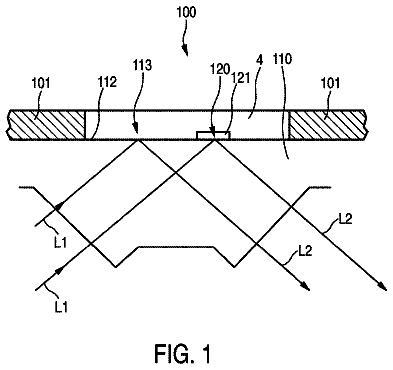
A sensing device ( 100 ) detects a target substance ( 2 ) in an investigation region ( 113 ).
US 9,804,094 B2 · Assignee: Hitachi High-Technologies Corporation · Inventors: Kohara; Yoshinobu et al.
Sheet 1 of 12 from the published document. All sheets in the USPTO PDF
To improve the detection sensitivity, detection accuracy, and reproducibility when electrostatic discharge is generated in a sample solution and analysis is performed using light emission in the generated plasma. A flow channel 100 , which has cylindrical main portions each expanding conically from a narrow portion, is filled with a conductive sample solution, and an electric field is applied to the flow channel 100 to generate plasma in the generated air bubbles, so that the resulting light emission is measured.
JP 3932368 B (Patent Literature 1) is given as the background art of the present invention. Patent Literature 1 describes a method for generating plasma and a method for elemental analysis, each comprising the steps of providing a narrow portion in a flow channel made of an insulation material, the narrow portion having a cross-sectional area markedly smaller than a cross-sectional area of the flow channel; filling the flow channel and the narrow portion with a conductive liquid, and thereafter applying an electric field to the narrow portion, to conduct the electric field through the narrow portion, thereby generating plasma at the narrow portion. Patent Literature 1 also describes an apparatus for generating plasma, the apparatus for generating plasma comprising a narrow portion in a flow channel made of an insulation material, the narrow portion having a cross-sectional area markedly
1 of 12 drawing sheets so far from the published document, cropped to the drawing. Every sheet is in the USPTO PDF.
What the patent claimed, word for word. All of it is now free to use.
The present invention relates to a plasma spectrometer for analyzing a liquid sample using plasma emission.
JP 3932368 B (Patent Literature 1) is given as the background art of the present invention. Patent Literature 1 describes a method for generating plasma and a method for elemental analysis, each comprising the steps of providing a narrow portion in a flow channel made of an insulation material, the narrow portion having a cross-sectional area markedly smaller than a cross-sectional area of the flow channel; filling the flow channel and the narrow portion with a conductive liquid, and thereafter applying an electric field to the narrow portion, to conduct the electric field through the narrow portion, thereby generating plasma at the narrow portion. Patent Literature 1 also describes an apparatus for generating plasma, the apparatus for generating plasma comprising a narrow portion in a flow channel made of an insulation material, the narrow portion having a cross-sectional area markedly smaller than a cross-sectional area of the flow channel; and a means of applying an electric field to the narrow portion to conduct the electric field through the narrow portion; and an apparatus for emission spectroscopic analysis comprising the apparatus for generating plasma. CITATION LIST Patent Literature
Patent Literature 1: JP 3932368 B SUMMARY OF INVENTION Technical Problem
Patent Literature 1 describes, in relation to a flow channel and a narrow portion that has a cross-sectional area markedly smaller than a cross-sectional area of the flow channel, the sizes of and the ratio between the cross-sectional areas of the flow channel and the narrow portion. Patent Literature 1 also describes an embodiment of a planar flow channel in which the depths of the narrow portion and the main portion of the flow channel and the flow channel of the connection portion are constant.
Patent Literature 1 does not describe a flow channel with a three-dimensional expansion in which the depths of the narrow portion, the connection portion, and the main portion of the flow channel are not constant. However, as a result of study, it has been found that in a flow channel with a three-dimensional expansion in which the depth and the width of the flow channel increase from the narrow portion through the connection portion to the main portion of the flow channel, the intensity of plasma emission is advantageously increased than when a planar flow channel with a constant depth is used, while the flow channel with a three-dimensional expansion has a problem in the phenomenon reproducibility as the behavior of air bubbles and plasma is unstable. Thus, the present invention provides a plasma spectrometer with significantly improved detection sensitivity, detection accuracy, and phenomenon reproducibility by defining the shape of a flow channel with a three-dimensional expansion and thus significantly improving the phenomenon reproducibility.
Patent Literature 1 fails to describe the arrangement direction of the flow channel. However, it has been found that the arrangement direction of a flow channel has large influence on the phenomenon reproducibility under the measurement condition of a low flow rate of a sample solution or short voltage application intervals that is advantageous when a very small amount of sample is handled, in particular. Further, it has been found that the arrangement direction of a flow channel has large influence on the phenomenon reproducibility under the condition of, in particular, low phenomenon reproducibility. Thus, the present invention provides a plasma spectrometer with significantly improved detection sensitivity, detection accuracy, and reproducibility by appropriately defining the arrangement direction of the flow channel and thus improving the phenomenon reproducibility.
Patent Literature 1 neither describes performing measurement at positions other than the narrow portion nor improving the sensitivity based on a difference in the detection position. However, as a result of study, it has been found that performing measurement at positions other than the narrow portion has influence on the detection sensitivity. Thus, the present invention provides a plasma spectrometer with significantly improved detection sensitivity by selecting a target measurement region in the flow channel. Solution to Problem
The present invention includes a plurality of means for solving the aforementioned problem. According to one example thereof, there is provided a spectrometer for filling a flow channel having a narrow portion with a conductive liquid, applying an electrical field to the flow channel to generate air bubbles, and generating plasma in the air bubbles. A flow channel is used in which connection portions each connecting the narrow portion to one of main portions of the flow channel are substantially conical in shape, and the main portions of the flow channel are substantially cylindrical in shape.
According to another example, there is provided a spectrometer for filling a flow channel with a conductive liquid, applying an electrical field to the flow channel to generate air bubbles, and generating plasma in the air bubbles. The flow channel is arranged substantially in parallel with a vertical line.
According to still another example, there is provided a spectrometer for filling a flow channel having a narrow portion with a conductive liquid, applying an electrical field to the flow channel to generate air bubbles, and generating plasma in the air bubbles. A region adjacent to the narrow portion of the flow channel is a measurement target region. Advantageous Effects of Invention
According to the present invention, it is possible to, in a method of generating electrical discharge in a sample solution and performing analysis using light emission in plasma thereof, improve the detection sensitivity, detection accuracy, and phenomenon reproducibility by increasing the emission intensity and thus improving the reproducibility.
Other problems, configurations, and advantageous effects will become apparent from the following description of embodiments.
FIG. 1A is a diagram showing an exemplary flow channel of a plasma spectrometer of the present invention.
FIG. 1B is a diagram showing an exemplary arrangement of a flow channel, electrodes, and connectors.
FIG. 2 is a diagram showing an exemplary overall configuration of a plasma spectrometer.
FIG. 3A is a diagram showing an exemplary flow channel as a comparison target.
FIG. 3B is a diagram showing an arrangement of a flow channel as a comparison target, electrodes, and connectors.
FIG. 4A is a diagram showing an exemplary flow channel as a comparison target.
FIG. 4B is a diagram showing an arrangement of a flow channel as a comparison target, electrodes, and connectors.
FIG. 5 is a diagram showing the relationship among the difference in the flow channel, the average emission intensity of lead and coefficients of variation.
FIG. 6A is a diagram showing a view of the inside of a flow channel of a plasma spectrometer of the present invention.
FIG. 6B is a diagram illustrating FIG. 6A .
FIG. 6C is a diagram showing a view of the inside of a flow channel as a comparison target.
FIG. 7 is a diagram partly showing an exemplary configuration of a plasma spectrometer in which a flow channel is arranged in parallel with the vertical line.
FIG. 8 is a diagram showing coefficients of variation of the emission intensity of lead.
FIG. 9A is a diagram showing an exemplary flow channel.
FIG. 9B is a diagram showing an exemplary flow channel.
FIG. 9C is a diagram showing an exemplary flow channel.
FIG. 9D is a diagram showing an exemplary flow channel.
FIG. 9E is a diagram showing an exemplary flow channel.
FIG. 10A is a diagram showing an exemplary distribution of the atomic emission in a flow channel.
FIG. 10B is a diagram showing an exemplary distribution of the intensity ratio of the atomic emission to the background light in a flow channel.
FIG. 11A is a diagram showing an exemplary distribution of the atomic emission in a flow channel.
FIG. 11B is a diagram showing an exemplary distribution of the intensity ratio of the atomic emission to the background light in a flow channel.
FIG. 12A is a diagram showing an exemplary distribution of the atomic emission in a flow channel.
FIG. 12B is a diagram showing an exemplary distribution of the intensity ratio of the atomic emission to the background light in a flow channel.
FIG. 13 is a diagram showing an exemplary plasma spectrometer in which a narrow portion of a flow channel is arranged in parallel with the vertical line.
FIG. 14 is a diagram showing coefficients of variation of the emission intensity of lead.
The emission intensity of plasma will change depending not only on the applied voltage level or the voltage application time but also on the shape of a flow channel, the arrangement of electrodes, the composition of a sample solution, and the like. Thus, it is generally difficult to identify the conditions to generate plasma. However, the voltage to be applied is desirably greater than or equal to 500 V, more desirably, greater than or equal to 1 kV, further desirably, greater than or equal to 1.2 kV, and still further desirably, greater than or equal to 1.5 kV. The voltage application time is desirably greater than or equal to 0.1 millisecond, more desirably, greater than or equal to 1 millisecond, further desirably, greater than or equal to 5 milliseconds, and still further desirably, greater than or equal to 20 milliseconds.
A sample solution should be electrically conductive, and acids that are used in typical elemental analysis, for example, nitric acid is suitable. Besides, a variety of acids, such as hydrochloric acid or sulfuric acid, can also be used. Further, a solution containing electrically conductive salts can also be used.
An appropriate size of a flow channel will change depending not only on the applied voltage level or the voltage application time but also on the arrangement of electrodes, the composition of a sample solution, and the like. Thus, it is generally difficult to identify an appropriate size of the flow channel. However, the length of the flow channel in the voltage application direction is about 1 to 300 mm, desirably, about 3 to 20 mm, or more desirably, about 5 to 15 mm.
The “flow channel” as referred to herein is created using an insulating material, and has a shape with closed flow channel cross-sections. Herein, a flow channel through which a liquid flows only in one direction at a given point in time is considered. In the present invention, light emission is generated using electrodes and applying a voltage thereto. Thus, when the positions of the electrodes in the flow channel are clearly known, it is possible to regard the flow channel between the electrodes as a substantial flow channel range and regard the positions of the electrodes as the opposite ends of the flow channel.
In the present invention, a flow channel with a narrow portion is handled, and the flow channel also has a portion with a larger flow channel cross-section than the narrow portion due to the significance of the narrow section. Such a portion is called a main portion of the flow channel. In addition, a portion that connects the narrow portion and the main portion of the flow channel is called a connection portion of the flow channel. Herein, a spectrometer in which a narrow portion is located at a position other than the ends of the flow channel is supposed. Therefore, the connection portion of the flow channel and the main portion of the flow channel are provided on each of the flow upstream side and the flow downstream side of the narrow portion. It is generally difficult to define the boundary between the connection portion and the main portion of the flow channel. However, the connection portion of the flow channel refers to a portion in which the flow channel expands from the narrow portion toward the main portion of the flow channel, while the main portion of the flow channel refers to a portion in which the flow channel does not expand almost at all. When the boundary between the connection portion of the flow channel and the main portion of the flow channel cannot be clearly identified in terms of the above definition, it is also possible to regard that a portion in which the width of the flow channel expands up to about three times that of the narrow portion as the connection portion of the flow channel, and regard a portion that is away from the narrow portion more than that as the main portion of the flow channel. The connection portion and the main portion are located on each of the upstream and downstream sides of the flow channel. However, a shape that is defined in an example of the present invention applies to the connection portion and the main portion on at least one of the upstream side or the downstream side. Needless to say, the shape defined in the present invention can also be applied to the connection portion and the main portion on each of the upstream side and the downstream side.
An example of the present invention is directed to not a planar flow channel in which the depths of a narrow portion, a connection portion, and a main portion of the flow channel are constant but a flow channel with a three-dimensional expansion in which both the depths and the widths of a connection portion and a main portion are increased as compared to those of a narrow portion. An example of the most appropriate flow channel shape is a flow channel in which a connection portion that connects a narrow portion to a main portion of the flow channel is substantially conical in shape, and the main portion of the flow channel is substantially cylindrical in shape.
As a conical shape of the connection portion of the flow channel, a conical shape having a half apex angle of about 10° to 80° is appropriate. If the angle is too far from such a range, the behavior of air bubbles that are generated from the narrow portion and spread to the opposite sides thereof would become unstable, with the result that phenomenon reproducibility would decrease. In addition, a connection portion that is substantially conical in shape refers to, if a perfect cone shape cannot be provided, a shape with a certain high degree of axial symmetry, such as an elliptical conical shape or a polygonal conical shape. When the axial symmetry is high, the behavior of air bubbles can be stable, which leads to high phenomenon reproducibility. When the shape of the connection portion is difficult to discriminate, it is possible to substantially regard, in each flow channel cross-section that is perpendicular to the center axis of the connection portion, a shape whose ratio of the longest line segment to the shortest line segment, which pass through the center, is less than or equal to 2:1, as a conical shape, which is desirable as a certain degree of phenomenon reproducibility is maintained.
A main portion of the flow channel that is substantially cylindrical in shape refers to a shape of the main portion that has, when a perfect cylindrical shape cannot be provided, high axial symmetry, is straight, and has no change in the cross-section, such as an elliptical column or a polygonal column. When the main portion has such a shape, the behavior of air bubbles that are generated from the narrow portion and spread to the main portion can be more stable, with the result that phenomenon reproducibility can be improved. Further, such a shape also has the advantageous effect that the phenomenon reproducibility is maintained as the generated air bubbles will be cleanly removed from the flow channel upon transfer of a liquid, and thus the air bubbles will not remain when a voltage is applied next time. In particular, in view of removing air bubbles, the main portion desirably has no change in the shape or the cross-section. Even if the main portion has a change in the shape or the cross-section, the change rate of the area of the flow channel cross-section, which is perpendicular to a line that connects the center line of the main portion, is desirably less than or equal to 2 times. Air bubbles are likely to accumulate in a portion, which has a large cross-sectional area, of the main portion of the flow channel. Thus, when the cross-sectional area changes, the largest cross-sectional area is desirably located not close to the narrow portion but around an end of the flow channel that has little influence on the light emission. In addition, in view of removing air bubbles, the main portion of the flow channel is desirably as straight as possible, and even when the main portion is not perfectly straight, no problem would arise as long as the curve of the line that connects the center of the main portion of the flow channel has an angle that is less than or equal to 60°. In view of the stability of when air bubbles grow, the center axis of the narrow portion desirably coincides with that of the main portion. However, even if they deviate from each other, the phenomenon reproducibility can be sufficiently high as long as the ratio of the amount of deviation to the width of the flow channel cross-section of the main portion in the direction of the deviation is less than or equal to ½.
In order to remove the generated air bubbles through transfer of a liquid, the flow channel cross-section of the main portion of the flow channel is desirably about the same size as or smaller than the size of the generated air bubbles or half the volume of the generated air bubbles so that the generated air bubbles can be removed through transfer of a liquid. As a result of study, it has been found that the typical size of air bubbles is about 10 μL. In consideration of the diameter of the corresponding sphere, the maximum width of the flow channel cross-section is desirably less than or equal to about 2.7 mm.
Meanwhile, when the width of the flow channel in the vertical direction is greater than that in the horizontal direction, there may be cases where the generated air bubbles flow up in the flow channel, and thus are not sufficiently washed away. Thus, the width of the main portion of the flow channel in the vertical direction is desirably about the same size as or smaller than that in the horizontal direction.
In an example of the present invention, in regard to the arrangement direction of the flow channel, the flow channel is arranged substantially in parallel with the vertical direction. This is because the generated air bubbles will be removed through transfer of a liquid most naturally due to the buoyancy effect, so that the phenomenon reproducibility is maintained. Such an arrangement has a prominent effect, in particular, under the conditions that are disadvantageous in maintaining the phenomenon reproducibility such that the amount of a transferred liquid is small and the voltage application intervals are short. The most desirable configuration is that a flow channel be straight, and a straight line that passes though the center of the flow channel be arranged in parallel with the vertical line. Practically, as long as the internal angle between the line that passes through the center of the flow channel and the vertical line is less than or equal to 60°, sufficient buoyancy will act upon the air bubbles, having the effect of maintaining the phenomenon reproducibility. It is also important to arrange the narrow portion in parallel with the vertical direction. In such a case also, as long as the interior angle between the narrow portion and the vertical line is less than or equal to 60°, sufficient buoyancy will act upon the air bubbles, having the effect of maintaining the phenomenon reproducibility. In any case, the movement direction of a fluid is desirably set in the direction from the lower side of the vertical direction to the upper side of the vertical direction. In regard to the polarity of each electrode, as the amount of air bubbles that are generated on the negative electrode side is larger than that on the positive electrode side, it is desirable to use the electrode on the upper side of the vertical direction as the negative electrode and use the electrode on the lower side of the vertical direction as the positive electrode so as to avoid entry of air bubbles, which have been generated on the negative electrode side, into the flow channel.
In an embodiment of the present invention, measurement is desirably performed in a region that is adjacent to the narrow portion of the flow channel. This is because in the connection portion on the positive electrode side that is adjacent to the narrow portion of the flow channel, atomic emission is as strong as or stronger than that in the narrow portion, and the intensity ratio of the atomic emission to the background light is the maximum. In particular, the intensity ratio of the atomic emission to the background light is the maximum at a portion, which does not include an extension of the narrow portion, in the connection portion. When measurement is performed in such regions, measurement with high detection sensitivity becomes possible.
Embodiments of the present invention will be hereinafter described with reference to the drawings.
Embodiments
[Embodiment 1]
This embodiment will describe an example of a plasma spectrometer.
FIG. 1A is a diagram illustrating an example of a flow channel 100 of a plasma spectrometer in this embodiment. The flow channel 100 is a flow channel having widths A and A′ and an overall length B, and having a narrow portion with widths a and a′ and a length b at the center. The narrow portion, the connection portions, and the main portions of the flow channel are displayed altogether. The widths a and a′ of the narrow portion are narrower than the width A of the flow channel, and is desirably less than or equal to ⅓, or further desirably, less than or equal to ⅕ the width A of the flow channel. The length b of the narrow portion is shorter than the overall length B of the flow channel 100 , and is desirably less than or equal to ⅕, or further desirably, less than or equal to 1/10 the overall length B of the flow channel 100 . The overall length B of the flow channel is desirably greater than or equal to 1 mm and less than or equal to 300 mm.
The present invention is directed to not a planar flow channel in which the depths of a narrow portion, connection portions, and main portions of the flow channel are constant but a flow channel with a three-dimensional expansion in which both the depths and the widths of connection portions and main portions are increased as compared to those of a narrow portion. An example of the most appropriate flow channel shape is a flow channel in which a connection portion leading from a narrow portion to a main portion of the flow channel is substantially conical in shape, and the main portion of the flow channel is substantially cylindrical in shape. The widths A and A′ are desirably substantially equal. Herein, a flow channel having a main portion with a perfect circle cross-section was used, and the widths A and A′ were set to 1.6 mm. For the cross-section of the narrow portion, a square cross-section was used, and the widths a and a′ were set to 0.2 mm. When not a roundish cross-sectional shape like a cylinder but a square cross-section with straight sides is adopted, there is an advantage in that measurement of light emission from the inner side of the narrow portion becomes easier. The length b of the narrow portion was set to 0.64 mm.
The connection portion for connecting the narrow portion to a portion, which has the widths A and A′, of the main portion of the flow channel was formed in a conical shape having a half apex angle θ of 27°, which is the angle from the center axis that penetrates the narrow portion so that the center axes that penetrate the narrow portion, the connection portion of the flow channel, and the main portion of the flow channel coincided with one another. When the angle is represented by the apex angle of a cone, it is represented as 54°. When a shape that is symmetrical about the center axis is selected as describe above, it becomes possible to improve the phenomenon reproducibility of the plasma emission phenomenon. As such a connection portion can be produced only by processing a flow channel, for example, by opening a hole in the flow channel with a drill from a plane at an end of the flow channel of a material and polishing it, there is an advantage in that the processing cost can be reduced than those of other complex structures. The apex angle of the cone may be any angle as long as it is not a too acute angle. For example, the angle may be in the range of a half apex angle of about 10° to 80°.
As a material for forming the flow channel, an insulating material that has light-transmitting performance with respect to light at a measurement target emission wavelength and has resistance to, in particular, acids of all chemicals is desirably used. For example, a variety of optical glass, resin for optical components, and the like can be adopted. In this embodiment, quartz glass 101 with a high UV-transmitting property and high shock resistance was used as the material of the flow channel.
FIG. 1B is a diagram illustrating an example of the relationship among the flow channel 100 , electrodes, connectors, and pipes. At the right side end of the flow channel 100 , a connector 120 is connected to the quartz glass 101 via an O-ring 123 using a pressure method to avoid leakage of liquid that would occur when the liquid is flowed from the outside. An electrode 121 and a pipe connection port 122 are fixed to the connector 120 . A pipe 124 is connected to the pipe connection port 122 . In this embodiment, a platinum wire with a diameter of 0.5 mm was used as the electrode 121 . A tip end of the electrode 121 is arranged such that it is located at an end of the flow channel 100 . A cavity in the connector 120 is a portion through which a liquid such as a sample solution passes, and desirably has a structure that is connected directly from the end of the flow channel and has the same diameter as the flow channel so as to facilitate passage of air bubbles and the like. Herein, the diameter of the cavity in the connector 120 was set to 1.6 mm. In addition, Teflon was used as the material of the connector 120 . As with the right side end of the flow channel 100 , an O-ring 128 , a connector 125 , an electrode 126 , a pipe connection port 127 , and a pipe 129 are also arranged at the left side end. The electrodes 121 and 126 are located at the centers of the connectors 120 and 125 , respectively, and lines that connect the respective electrodes and the narrow portion are straight lines.
FIG. 2 is a schematic diagram showing an exemplary configuration of the plasma spectrometer in this embodiment. Description of the connection around the flow channel 100 will be omitted as it is shown in FIG. 1B . A syringe pump 140 is connected to the pipe 124 . By controlling the syringe pump 140 , it is possible to transfer a solution in the syringe pump 140 to the flow channel 100 . The syringe pump 140 is connected to a computer 150 via a signal line 149 , so that the operation thereof is controlled by the computer 150 . A waste liquid container 141 is arranged at an end of the other pipe 129 .
The electrodes 121 and 126 are connected to a power supply 152 via high-voltage cables 155 and 156 , respectively. In this embodiment, a DC pulse power supply was used as the power supply 152 . An ammeter 154 for measuring current is connected in series with the high-voltage cable 156 . The computer 150 is connected to the power supply 152 via a signal line 151 , and can set the output voltage of the power supply 152 and control the on/off timing using a trigger on the basis of input information. In addition, the computer 150 is connected to the ammeter 154 via a signal line 153 , and captures the measurement data of the ammeter 154 and further performs information processing on the measurement data, so that the data can be used to control the power supply 152 .
An optical fiber end 143 is one end of an optical fiber 144 , and is arranged toward the flow channel 100 . The other end of the optical fiber 144 is connected to a spectroscope 145 . Light that is received by the optical fiber end 143 is input to the spectroscope 145 via the optical fiber 144 and is subjected to spectral observation. The spectroscope 145 is connected to the computer 150 via a signal line 147 so that the spectroscope 145 can be controlled from the computer 150 .
An imaging device 146 such as a CCD camera is connected as a detector to the spectrometer 145 , and receives light spectrally observed by the spectrometer 145 . The imaging device 146 is connected to the computer 150 via a signal line 148 so that the imaging device 146 can be controlled from the computer 150 . Information on the spectrum measured by the imaging device 146 can be recorded on a storage device in the computer 150 and subjected to information processing. Data related to the light emission, in combination with data on a temporal change of current, which has been measured with the ammeter 154 and recorded on the recording device of the computer 150 , can be processed by the computer 150 . As described above, the computer 150 has the function of the control unit and the function of the arithmetic unit at the same time.
The procedures to supply as a sample solution a decinormal nitric acid solution containing 100 ppm lead to the flow channel in the plasma spectrometer shown in FIGS. 1A, 1B and 2 , and apply a voltage thereto to measure light emission are described below. Among emission spectra measured by the imaging device 146 via the spectroscope 145 , an emission spectrum of an emission line derived from lead (405.78 nm) was focused, and a net emission intensity obtained by subtracting the background light intensity from the intensity of the emission spectrum was measured as the emission intensity derived from lead. It should be noted that the solution containing lead was used as the sample solution herein only for illustration purposes. Thus, a solution containing other elements can also be analyzed through similar procedures, so that a similar phenomenon and advantageous effects can be observed.
Water was first introduced into the flow channel 100 that is empty, and then, decinormal nitric acid was flowed to clean the flow channel 100 . First, water was poured into a syringe of the syringe pump 140 , and then, the syringe pump 140 was moved in accordance with an instruction from the computer 150 , so that the water was flowed into the flow channel 100 via the pipe 124 , the pipe connection port 122 , and the inside of the connector 120 to clean the flow channel 100 , and then, the water having cleaned the flow channel 100 was collected into the waste liquid container 141 via the inside of the connector 125 , the pipe connection port 127 , and the pipe 129 on the downstream side. Next, decinormal nitric acid was flowed in accordance with similar procedures to clean the flow channel 100 .
Next, a decinormal nitric acid solution containing 100 ppm lead was poured as a sample solution into the flow channel 100 in accordance with similar procedures to conduct light emission with the application of a voltage. An appropriate voltage applied herein is desirably greater than or equal to 500 V, more desirably, greater than or equal to 1 kV, further desirably, greater than or equal to about 1.2 kV, and still further desirably, greater than or equal to 1.5 kV. The voltage application time is desirably greater than or equal to 0.1 millisecond, more desirably, greater than or equal to 1 millisecond, further desirably, greater than or equal to 5 milliseconds, and still further desirably, greater than or equal to 20 milliseconds. Herein, the applied voltage was set to 1.5 kV, and the pulse width of the applied voltage was set to 5 milliseconds.
In this embodiment, the polarity of the power supply 152 was set so as to apply a positive high voltage to the high-voltage cable 155 and apply the ground potential to the high-voltage cable 156 . That is, the polarity of the electrode was set so that the electrode 121 on the upstream side of the transferred sample solution became a negative electrode while the electrode 126 on the downstream side of the transferred sample solution became a positive electrode. The relationship between the polarities of the electrodes and the direction of the flow of the sample solution are not limited to such combination, and may be an opposite combination.
The computer 150 generates a voltage application start signal. The power supply 152 , upon receiving the signal from the computer 150 , applies a voltage to the flow channel 100 in accordance with the signal. Exposure control of the imaging device 146 was performed by inputting a signal, which is similar to a voltage application signal, to the imaging device 146 from the computer 150 . Measurement of current with the ammeter 154 was performed by outputting a signal, which is synchronized with the voltage application start signal transmitted to the power supply 152 , from the computer 150 , and inputting the signal as a signal to the ammeter 154 .
In the plasma spectrometer that uses the flow channel 100 shown in FIGS. 1A and 1B , emission intensity that is far higher than that of the conventional plasma spectrometer is obtained, and an analysis result in which the coefficient of variation of the emission intensity is about 1%, which shows quite high reproducibility as the electrostatic discharge measurement, can be obtained. For comparison purposes, a result obtained by measuring the light emission of lead using two flow channels, which differ from those in FIGS. 1A and 1B , in the same way are described below.
FIG. 3A is a diagram illustrating an example of a flow channel 200 as a comparison target. The flow channel 200 is a flow channel that is created in quartz glass 201 , has a width A, an overall length B, and a height C, has a narrow portion with widths a and c and a length b at the center, and has connection angles θ 1 and θ 2 . The narrow portion, the connection portions, and the main portions of the flow channel are displayed altogether. Herein, the width A is 1.6 mm, the overall length B is 10.5 mm, and the height C is 5 mm. The cross-section of the narrow portion has widths a and c of 0.1 mm, and a length b of 0.5 mm. The angles θ 1 and θ 2 of the connection portion are 45°. The flow channel 200 is not a planar flow channel in which the depths of a narrow portion, connection portions, and main portions of the flow channel are constant but a flow channel with a three-dimensional expansion in which both the depths and the widths of connection portions and main portions are increased as compared to those of a narrow portion as with the flow channel 100 . However, shown herein is an example of a flow channel shape in which the symmetry of expansion is low and each main portion of the flow channel also has a shape with a low axial symmetry. When this is described with the bottom diagram of FIG. 3A , the flow channel in the connection portion expands only upward in the vertical direction, and does not expand downward. That is, the flow channel obviously has an asymmetrical shape. In addition, the shape of the flow channel cross-section of each main portion of the flow channel leading toward a round hole at an end of the flow channel is irregular and is not a shape like a cylinder or a polygonal column that has high symmetry, is straight, and has no change in the cross-sectional area.
FIG. 3B is a diagram illustrating an example of the relationship among the flow channel 200 , electrodes, connectors, and pipes. At the right side end of the flow channel 200 , a connector 220 is connected to the quartz glass 201 via an O-ring 223 , and an electrode 221 and a pipe connection port 222 are fixed to the connector 220 . A pipe 224 is connected to the pipe connection port 222 . An end of the electrode 221 is arranged so as to be located at an end of the flow channel 200 . As with the right side end of the flow channel 200 , an O-ring 228 , a connector 225 , an electrode 226 , a pipe connection port 227 , and a pipe 229 are also arranged at the left side end. The electrodes 221 and 226 are located at the centers of the connectors 220 and 225 , respectively. It is seen that unlike the flow channel 110 shown in FIGS. 1A and 1B , a line that connects the center of the flow channel 200 is not a straight line but a curved line with a large angle. The flow channel cross-sectional area of each main portion of the flow channel changes by five times or more, which exhibits a high change rate.
FIG. 4A is a diagram showing another example of a flow channel 300 as a comparison target. The flow channel 300 is a flow channel that is created in quartz glass 301 , and has a width A, an overall length B, a height C, has a narrow portion with a width a and a length b at the center, and has a connection angle θ. The flow channel has a uniform depth c, and has a height C including the connection portions. The narrow portion, the connection portions, and the main portions of the flow channel are displayed altogether. Herein, the width A is 3 mm, the overall length B is 10.5 mm, and the height C is 2 mm. The width a of the cross section is 0.1 mm, and the length b thereof is 0.4 mm. The angle θ of the connection portion is 45°, and the depth c of the flow channel is 0.08 mm. The flow channel 300 is also a flow channel having a narrow portion at the center like the flow channel 100 , but is a flow channel with a planar structure in which the depth of the flow channel is constant at portions excluding the portions connected to the connecters.
FIG. 4B is a diagram illustrating an example of the relationship among the flow channel 300 , electrodes, connectors, and pipes. At the right side end of the flow channel 300 , a connector 320 is connected to the quartz glass 301 via an O-ring 323 , and an electrode 321 and a pipe connection port 322 are fixed to the connector 320 . A pipe 324 is connected to the pipe connection port 322 . An end of the electrode 321 is arranged so as to be located at an end of the flow channel 300 . As with the right side end of the flow channel 300 , an O-ring 328 , a connector 325 , an electrode 326 , a pipe connection port 327 , and a pipe 329 are also arranged at the left side end. The electrodes 321 and 326 are located at the centers of the connectors 320 and 325 , respectively.
The description continues in the full USPTO document.
About 6,773 words. The USPTO PDF has it with every drawing.
Fees are due 3.5, 7.5 and 11.5 years after grant. This patent expired on October 31, 2025, so the fee marked "not paid" was the one that went unpaid.
PLASMA SPECTROMETER
Filed Nov 2012 · published Jan 2015Plasma spectrometer
Filed Nov 2012 · granted Oct 2017Earlier publications, parents and continuations. None of them can still be enforced, or this patent would not be listed.
Prior art cited by the examiner or applicant. Useful when you check your own idea for novelty.
Everything on this page comes from the documents linked above.


