 Lapsed, fee not paid3 drawings
Vehicles & Drones · US 9,803,740 B2
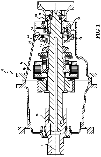
Pump for a torque transfer mechanism
A torque transfer mechanism for a vehicle, including a housing and a pump disposed therein.
US 9,804,012 B2 · Assignee: Rohm Co., Ltd. · Inventors: Marumoto; Kyoji et al.
Sheet 1 of 25 from the published document. All sheets in the USPTO PDF
The vehicle traveling information recording device of the present invention comprises a camera unit for acquiring image information relating to outside of a vehicle; a recording unit for recording the image information from the camera unit; an abnormality detection unit for detecting an abnormal vehicle state; an auxiliary data detection unit for acquiring auxiliary data when the abnormality detection unit has detected an abnormality; and a control unit for combining the auxiliary data with the image information in the recording unit when the abnormality detection unit has detected the abnormality, and recording image information after the combination related to abnormality detection.
1 of 25 drawing sheets so far from the published document, cropped to the drawing. Every sheet is in the USPTO PDF.
What the patent claimed, word for word. All of it is now free to use.
The present invention relates to a vehicle traveling information recording device such as a drive recorder. Background Art First Background Art
Drive recorders keep a record of evidence just prior to an accident by saving information in memory that relates to the vehicle exterior and vehicle state before and after an accident has occurred, and are beginning to be widely used in recent years as effective means for preventing automobile accidents in advance. Various drive recorders have been proposed. In Patent Literature 1, for example, a drive recorder is proposed for preventing overwriting and falsification of data by providing means for blocking input to memory after an accident. Second Background Art
Drive recorders keep a record of evidence just prior to an accident by saving information in memory that relates to the vehicle exterior and vehicle state before and after an accident, and are beginning to be widely used in recent years as effective means for preventing automobile accidents in advance. Various drive recorders have been proposed. Patent Literature 2, for example, proposes a travel recording system capable of ascertaining the color of a signal lamp when the vehicle has entered an intersection. Third Background Art
Drive recorders keep a record of evidence just prior to an accident by saving information in memory that relates to the vehicle exterior and vehicle state before and after an accident, and are beginning to be widely used in recent years as effective means for preventing automobile accidents in advance. Various drive recorders have been proposed. In Patent Literature 1, for example, it is proposed that data after an accident is prevented from being overwritten by transmitting data recorded before and after an accident via an antenna. Fourth Background Art
In recent years, headlight control in vehicles have become more automated, and it is becoming common to automatically switch on headlights near dusk or when the vehicle has entered a tunnel during daylight by automatically controlling the headlights in accordance with the brightness outside the vehicle. Various proposals have been made for automatically turning on the headlights. For example, in Patent Literature 3, it is proposed that headlights and vehicle side lights be controlled in accordance with the state of the turn indicator while traveling or when stopped and the state of the headlights when a radio wave is received from a ground station disposed in an intersection or a crosswalk, and the headlights are, e.g., automatically switched off (or dimmed) when the turn indicator is not active while the vehicle is stopped. In Patent Literature 1, it is also proposed that the headlights be turned off or dimmed or that the illumination angle be modified when it has been recognized that the vehicle is stopped, or that a traffic light is red as determined by color information analysis carried out by processing images obtained from an onboard camera. Fifth Background Art
Various proposals have been made in recent years for vehicle travel safety. A drive recorder is an example that is used as evidence when an accident or the like has occurred, by recording travel and driving conditions. Proposals have been made not only for keeping a past record merely as evidence, but also for making positive future improvements. For example, there has been proposed a system capable of efficiently diagnosing the driving skill of the driver (Patent Literature 4), and a drive recorder capable of providing exact instruction and evaluation of driving to the operator (Patent Literature 5). Sixth Background Art
Various proposals have been made in recent years for vehicle travel safety. A drive recorder is an example that is used as evidence when an accident or the like has occurred, by recording travel and driving conditions. Proposals have been made not only for keeping a past record merely as evidence, but also for making positive future improvements. For example, there has been proposed a system capable of efficiently diagnosing the driving skill of the driver (Patent Literature 4), and a drive recorder capable of providing exact instruction and evaluation of driving to the operator (Patent Literature 5). On the other hand, there has also been proposed a vehicle recording device having a communication function, i.e., a vehicle history information management system (Patent Literature 6) that can, e.g., encode and transmit history information related to various activity histories in a vehicle and thereby prevent falsification or the like of information. LIST OF CITATIONS Patent Literature
Patent Literature 1: Japanese Laid-open Patent Application No. 2006-306153 Patent Literature 2: Japanese Laid-open Patent Application No. 2008-230434 Patent Literature 3: Japanese Laid-open Patent Application No. 2003-123186 Patent Literature 4: Japanese Laid-open Patent Application No. 2002-211265 Patent Literature 5: Japanese Laid-open Patent Application No. 2007-199791 Patent Literature 6: Japanese Laid-open Patent Application No. 2003-87234 SUMMARY OF INVENTION Technical Problem
However, drive recorders have a variety of diverse problems that need to be resolved in terms of practicality.
In view of the above, an object of the present invention is to provide a vehicle traveling information recording device that records a large amount of information. Solution to Problem
In order to achieve the objects described above, the vehicle traveling information recording device according to the present invention has a configuration (first aspect) comprising a camera unit for acquiring image information relating to outside of a vehicle; a recording unit for recording the image information from the camera unit; an abnormality detection unit for detecting an abnormal vehicle state; an auxiliary data detection unit for acquiring auxiliary data when the abnormality detection unit has detected an abnormality; and a control unit for combining the auxiliary data with the image information in the recording unit when the abnormality detection unit has detected the abnormality, and recording the combined image information as image information related to abnormality detection.
In the vehicle traveling information recording device according to the first aspect, it is possible to use a configuration (second aspect) in which the control unit combines the auxiliary data with the image information in the recording unit as a digital watermark.
In the vehicle traveling information recording device according to the first aspect, it is possible to use a configuration (third aspect) in which the auxiliary data detection unit acquires position data of the vehicle.
In the vehicle traveling information recording device according to the first aspect, it is possible to use a configuration (fourth aspect) in which the auxiliary data detection unit has a signal information unit for acquiring signal lamp information in the running direction of the vehicle.
In the vehicle traveling information recording device according to the fourth aspect, it is possible to use a configuration (fifth aspect) in which the signal information unit comprises a receiving unit for receiving signal lamp information; a detection unit for detecting running direction information of the vehicle; a sorting unit for sorting signal lamp information in the traveling direction of the vehicle from the signal lamp information received by the receiver unit on the basis of the running direction information of the vehicle detected by the detection unit; and a recording unit for recording signal lamp information in the traveling direction of the vehicle sorted by the sorting unit.
The vehicle traveling information recording device according to the fifth aspect may have a configuration (sixth aspect) comprising a control unit for controlling the headlights on the basis of the signal lamp information in the traveling direction of the vehicle sorted by the sorting section.
The vehicle traveling information recording device according to the sixth aspect may have a configuration (seventh aspect) comprising a brake operation unit and a time-elapsed detection unit for detecting that a predetermined time has elapsed after the brake operation unit has been operated, wherein the control unit changes the state of the ordinarily lighted headlights when the time-elapsed detection unit has detected that a predetermined time has elapsed after brakes have been operated, and the signal lamp information in the traveling direction of the vehicle, having been sorted by the sorting unit, is in a vehicle-stop instruction state.
In the vehicle traveling information recording device according to the fifth aspect, it is possible to use a configuration (eighth aspect) in which the signal information unit comprises a position information acquisition unit for acquiring position information of a vehicle on a map, and a control unit for incorporating the information of a signal lamp installation position on a map held in the position information acquisition unit into the record of the signal lamp information performed by the recording unit.
The vehicle traveling information recording device according to the first aspect may have a configuration (ninth aspect) comprising a switching unit for switching the vehicle between a travel-enabled state and a travel-disabled state, a checking unit for checking whether the recording of traveling information performed by the recording unit is enabled each time the switching unit sets the vehicle in the travel-enabled state, and a reporting unit for reporting the checking results of the checking unit.
The vehicle traveling information recording device according to the first aspect may have a configuration (tenth aspect) comprising a switching unit for switching the vehicle between a self-powered-travel-enabled state and a self-powered-travel-disabled state, and a control unit for maintaining functioning of the camera unit and the recording unit even when the switching unit has set the vehicle in a self-powered-travel-disabled state.
The vehicle traveling information recording device according to the first aspect may have a configuration (eleventh aspect) in which the auxiliary data detection unit acquires the operating data of the vehicle.
The vehicle traveling information recording device according to eleventh aspect may have a configuration (twelfth aspect) comprising a fuel economy gauge, and a control unit for analyzing the relationship between the fuel economy information of the fuel economy gauge and the operating data of the vehicle.
The vehicle traveling information recording device according to the present invention has a configuration (thirteenth aspect) comprising a fuel economy gauge, a traveling information detection unit, and a control unit for using the traveling information detection unit to classify the fuel economy information of the fuel economy gauge.
In the vehicle traveling information recording device according to the thirteenth aspect, it is possible to use a configuration (fourteenth aspect) in which the control unit classifies the fuel economy information of the fuel economy gauge into a flat-ground-constant-speed state and states other than the flat-ground-constant-speed state.
The vehicle traveling information recording device according to the fourteenth aspect may have a configuration (fifteenth aspect) comprising a vehicle operating data recording unit, wherein the control unit analyzes the relationship between fuel economy information of states other than the flat-ground-constant-speed state and the vehicle operating data.
The vehicle traveling information recording device according to the thirteenth aspect may have a configuration (sixteenth aspect) comprising a notification unit for providing notification on the basis the information of the traveling information detection unit, and a control unit for controlling the notification timing by the notification unit.
The vehicle traveling information recording device according to the thirteenth aspect may have a configuration (seventeenth aspect) comprising a transmitting unit for transmitting the vehicle information acquired by the fuel economy gauge to the exterior, and a receiving unit for receiving statistical information of fuel economy information collected from numerous vehicles.
The vehicle traveling information recording device according to the present invention has a configuration (eighteenth aspect) comprising a vehicle information acquisition unit; a transmitting unit for transmitting the vehicle information acquired by the vehicle information acquisition unit to the exterior; a receiving unit for receiving statistical information of vehicle information collected from numerous vehicles; and a controlling unit for comparing the statistical information received by the receiving unit and the vehicle information acquired by the vehicle information acquisition unit.
In the vehicle traveling information recording device according to the eighteenth aspect, it is possible to use a configuration (nineteenth aspect) in which the vehicle information acquisition unit includes a fuel economy gauge, and the statistical information includes information that indicates the distribution state of the fuel economy information collected from numerous vehicles.
In the vehicle traveling information recording device according to the eighteenth aspect, it is possible to use a configuration (twentieth aspect) in which the numerous vehicles are limited to the same vehicle. Advantageous Effects of the Invention
As described above, in accordance with the present invention, it is possible to provide a vehicle traveling state recording device that provides greater reliability of the evidentiary strength of recorded abnormality information.
FIG. 1 is a block view (Example 1) showing the first example of the drive recorder system according to the present invention;
FIG. 2 is basic flowchart showing the functions of the vehicle control unit in the first example of FIG. 1 ;
FIG. 3 is a flowchart showing the details of step S 22 of FIG. 2 ;
FIG. 4 is a timing chart showing the record obtained by FIFO recording of step S 12 of FIG. 2 ;
FIG. 5 is a flowchart showing the details of step S 12 of FIG. 2 ;
FIG. 6 is a flowchart showing the details of step S 24 of FIG. 2 ;
FIG. 7 is a flowchart showing the details of step S 2 of FIG. 2 ;
FIG. 8 is a flowchart showing the details of step S 16 of FIG. 2 ;
FIG. 9 is a basic flowchart (Example 2) showing the functions of the vehicle control unit in the second example of the drive recorder system according to the present invention;
FIG. 10 is a flowchart showing the details of step S 216 of FIG. 9 ;
FIG. 11 is a flowchart showing the details of step S 220 of FIG. 9 ;
FIG. 12 is a flowchart showing the details of digital watermarking in step S 214 of FIG. 9 ;
FIG. 13 is a block view (Example 3) showing the third example of the drive recorder system according to the present invention;
FIG. 14 is a basic flowchart showing the functions of the vehicle control unit in the third example in FIG. 13 ;
FIG. 15 is a flowchart showing the details of step S 286 of FIG. 14 ;
FIG. 16 is a flowchart showing the details of another example of step S 286 of FIG. 14 ;
FIG. 17A is a partial perspective view of the operation unit 10 in the third example of FIG. 13 ;
FIG. 17B is a table of functions of the operation unit 10 in the third example of FIG. 13 ;
FIG. 18 is a block view (Example 4) showing the fourth example of the drive recorder system according to the present invention;
FIG. 19 is a basic flowchart showing the functions of the vehicle control unit 8 in the fourth example in FIG. 18 ;
FIG. 20 is a flowchart showing the details of drive analysis processing in steps S 356 and 358 of FIG. 19 ;
FIG. 21 is a flowchart showing the details of drive analysis data creation processing in step S 404 of FIG. 20 ;
FIG. 22 is a flowchart showing the details of initial function check processing/analysis notification processing in step S 352 of FIG. 19 ;
FIG. 23 is a flowchart showing the details of lamp control processing/analysis notification processing of FIG. 19 ;
FIG. 24 is a flowchart showing the details of information exchange processing in steps S 360 and S 220 ; and
FIG. 25 is a basic flowchart showing the functions of the server control unit 420 in the fourth example of FIG. 18 . DESCRIPTION OF EMBODIMENTS First Example
FIG. 1 is a block view showing the first example of the drive recorder system according to an embodiment of the present invention. The drive recorder system of the present example is designed for a vehicle 2 , i.e., a gasoline engine vehicle, an electric automobile, or a so-called hybrid vehicle in which a gasoline engine and a motor are used in combination, which are provided with a drive recorder for recording information before and after an accident, and is furthermore composed of a system that operates in coordination with a signal apparatus (a traffic light apparatus) 4 and a gasoline/charging station 6 .
The vehicle 2 has a vehicle control unit 8 comprising a computer for controlling the vehicle overall and for controlling a vehicle function unit 12 in accordance with operation of the operation unit 10 by the driver of the vehicle. The functions of the vehicle control unit 8 are executed by software stored in the recording unit 14 . The recording unit 14 temporarily stores various data required for controlling the vehicle overall. The vehicle control unit 8 controls a display unit 16 , displays a GUI required for operating the operation unit 10 , and displays the control results. The vehicle control unit 8 has a clock 18 , and the time information of the clock 18 is used in various functions. The time of the clock 18 is automatically corrected to the correct time as needed using external time information.
A GPS unit 20 acquires latitude, longitude, and elevation information as absolute position information of the vehicle 2 from satellites and the nearest broadcast station on the basis of a GPS system, and sends the information to the vehicle control unit 8 . A car navigation function unit 22 processes absolute position information received from the GPS unit 20 via the vehicle control unit 8 , and displays the position of the vehicle 2 on a map on the display unit 16 . The vehicle 2 is furthermore provided with a vehicle short-distance communication unit 24 , and receives information by radio wave or by light from signal apparatuses 4 and gasoline/charging stations 6 when in the vicinity thereof.
Next, the configuration related to driver recorder will be described as required in association with the configuration described above. Images of the forward direction of the vehicle and ambient sounds are constantly inputted when the vehicle 2 is in an operating state. An operating state is not only a state in which the vehicle is actually traveling, but is also a state in which the vehicle is temporarily stopped at a traffic light, and also includes all states in which a traffic accident may possibly occur in conjunction with the traveling of the vehicle 2 . In order to check whether such a state exists, the presence of a moving body is detected by image processing based on an image captured by a camera 26 , and images and sounds are delivered to the camera 26 and the microphone 28 provided that, for a predetermined continuous length of time thereafter, no confirmation is made of a state in which a moving body has not been detected in the image, even when the engine is stopped.
The vehicle control unit 8 is provided with a non-volatile buffer memory with a capacity of about 20 seconds, and image and sound information inputted from the camera 26 and the microphone 28 is stored in a first-in first-out (FIFO) format. In other words, the most recent 20 seconds of information continues to be constantly written over old data and stored. When a sharp change in acceleration has been detected by an acceleration detection unit 30 due to a collision or other adverse event, or a manual operation is made by the operation unit 10 , about 10 additional seconds of information continues to be stored in the buffer memory from that point forward as long as the camera 26 and the microphone 28 are not destroyed and the input information is continuous. Therefore, about 10 seconds of image and sound information is ultimately retained in the buffer memory before and after the point at which a change in acceleration has been detected or a manual operation has been carried out. This 10 seconds of before-and-after image and sound information undergoes predetermined processing by the vehicle control unit 8 , and is configured to be recorded as digitally compressed video information in a first recording unit 32 and a second recording unit 34 disposed in different portions of the vehicle 2 . The first recording unit 32 and the second recording unit 34 are each composed of non-volatile memory, and the recording is retained even when power has been cut off to these recording units due to an accident or the like. The first recording unit 32 and the second recording unit 34 have capacity for about 10 units of digitally compressed video information, and is overwritten in a FIFO format.
The first recording unit 32 is disposed in, e.g., the front portion of the vehicle and the second recording unit 34 is disposed in, e.g., the rear portion of the vehicle. The two units are configured so as to record the same information, and it is thereby expected that if one of the units is destroyed by chance in an accident, the other will remain viable and capable of recording. It is also expected that information that has already been recorded will remain in at least one of the units. A record of about 20 seconds prior to an accident will remain as long as the non-volatile buffer memory is safe, even when a majority of the drive recorder functions have been destroyed.
Here, the processing carried out by the vehicle control unit 8 will be described when images and sound are recorded in the first recording 32 and the second recording unit 34 . In addition to the processing for creating ordinary digitally compressed video information with sound, this processing includes processing for enhancing information as evidence as well as preventing falsification or substitution of the digitally compressed video information with sound to increase evidentiary strength.
The signal apparatus 4 is configured so as to enhance the evidentiary information, and a signal apparatus control unit 36 controls the red, green, and yellow signal lamps 38 . A signal apparatus short-distance communication unit 40 transmits information in the vicinity of the signal apparatus 4 to indicate the current colors of the signal lamps and to which of the intersecting roads they are oriented. The signal apparatus short-distance communication unit 40 also has a configuration that is used for transmitting traffic congestion information or the like in the vicinity of the signal apparatus 4 from the vehicle information communication system and obtained from a signal apparatus system communication unit 42 . Therefore, this information is received by the vehicle short-distance communication unit 24 and sent to the vehicle control unit 8 if a vehicle 2 is present in the vicinity of the intersection where the signal apparatus 4 is located. The state of a signal lamp 38 in the forward direction of the vehicle 2 can be acquired as information when a change in acceleration has been detected or when there has been a manual operation while the vehicle 2 is passing through the intersection or stopped at the traffic light. It is thus possible to ascertain the state of the signal lamp 38 until a change in acceleration is detected or a manual operation (hereinafter referred to as “occurrence of an accident” in a typical case) is made, even when the state of the signal lamp 38 cannot be obtained from images from the camera 26 due to a limited angle of view of the camera 26 or due to synchronization [problems] between the camera 26 and the signal lamp 38 . A direction detection unit 44 detects the direction in which the vehicle 2 is oriented immediately prior to the occurrence of an accident, and in combination with information from the signal apparatus 4 described above, provides evidence to the vehicle 2 of whether an signal was ignored when an accident has occurred.
The vehicle control unit 8 receives speed information from a speedometer 46 , and sequentially overwrites old data and records the speed information in FIFO format so as to use about 20 seconds of capacity in the nonvolatile buffer memory. It is therefore possible to ascertain the relationship between the speed at the time of an accident and the speed limit, the brake operation history about 20 seconds prior to an accident, and other factors. Such speed information at the time of an accident and the brake operation history are digitally watermarked together with the signal lamp information in the forward direction at the time of an accident, the accident occurrence time information from the clock 18 , and accident geographical point information from the GPS unit 20 , sent to the epi-illumination source 48 and handled as digitally watermarked data. The operation information of the brakes or the like can be indirectly ascertained from the speed information as described above and can be sent directly to the vehicle control unit 8 from the wafer 10 . Therefore, the operation history information can also be sequentially written over old data in a FIFO format in the nonvolatile buffer memory.
About 10 seconds of image and sound information obtained from before and after an accident and temporarily stored in the buffer memory is sent to a digital watermarking unit 48 and embedded with digital watermark data composed of the speed information, brake operation history, signal lamp information, time information, and geographical point information. Digital watermarking key information held in the recording unit 14 is set and used during the embedding process.
Image and sound information embedded in this manner with digital watermark data using digital watermarking key information is returned to the vehicle control unit 8 , digitally compressed, and sent to the first recording unit 32 and the second recording unit 34 , respectively. As described above, digital watermark information related to an accident is embedded in about 10 seconds of image and sound information both before and after an accident by using digital watermarking key information, and it is therefore difficult to falsify the image information and the sound information. The digital watermark information itself enhances the evidentiary information at the time of the accident by extracting the information.
The control of the drive recorder function was described above as being carried out by the vehicle control unit 8 , but in place of having the vehicle control unit 8 perform all functions, it is also possible to provide a separate, dedicated control unit assigned to the drive recorder function and to delegate functions. In this case as well, the drive recorder-dedicated control unit operates in coordination with the vehicle control unit 8 to execute functions overall such as those described above.
In the event that an accident has occurred, the constituent portions of the drive recorder function described above are stored in a section that cannot be accessed by the owner of the vehicle 2 and can be accessed by a qualified person during vehicle inspection or the like. Cables or the like that connect the camera 26 and the microphone 28 to the vehicle control unit 8 are also arranged in a section that is not visible to the owner of the vehicle 2 . Even when the drive recorder function is later added to the vehicle 2 , installation is limited to qualified personnel, and the cables or the like are disposed so that the owner of the vehicle 2 cannot remove them without authorization. Furthermore, if the cables are cut or drive recorder function has been otherwise damaged in error, the vehicle outside display unit 50 displays this fact on the exterior of the vehicle and a traffic violation will result when this display is discovered by police.
On the other hand, an initial check of the drive recorder function is carried out each time the vehicle 2 is started, and the display unit 16 displays that the status is normal. In place of a display, it is also possible to provide notification by announcement that the check results are normal, or both display and announcement may be used. Traffic accidents normally should not occur, and in fact it is likely that nothing will happen for many years for a safe driver. During this interval, the drive recorder has no opportunity to operate even once, but based on the configuration described above, the functions are checked to be normal on a daily basis, and it is possible to prevent a situation in advance in which information is by chance not recorded.
The gasoline filling/power feeding station 6 is provided with a station short-distance communication unit 52 for exchanging information with the vehicle 2 , which has stopped at a station for fueling or charging. The station control unit 54 acquires from the station system communication unit 56 the ID information of the vehicle 2 and the newest digital watermarking key information to be applied to the vehicle 2 . The newest digital watermarking key information is transmitted to the vehicle 2 by information exchange between the vehicle short-distance communication unit 24 and the station short-distance communication unit 52 , and is sent to the recording unit 14 by way of the vehicle control unit 8 to update the old digital watermarking key information. Updating such digital watermarking key information prevents falsification or substitution of image and sound information obtained by the drive recorder, and the update history of the digital watermarking key information of each vehicle is registered separately in a drive recorder management center. Therefore, digital image information created using expired digital watermarking key information is not recognized as a genuine recording. In the event that the digital watermarking key information has leaked out, the digital image information created using expired digital watermarking key information will not be recognized as a genuine recording. It is also possible to frequently update the digital watermarking key information from a signal apparatus 4 .
A gasoline filling/power feeding unit 58 fills gasoline/feeds power to a gasoline filling/power feeding opening 62 of the vehicle 2 via a gasoline filling/power feeding unit line 60 . At this point, the digital watermarking key information can be transmitted from the station control unit 54 to the vehicle control unit 8 by using power line communication (PLC) via the gasoline filling/power feeding unit line 60 in the case that the vehicle 2 is a electric automobile or a hybrid vehicle.
As described above, the owner of the vehicle 2 cannot modify the drive recorder information in the first example of the present invention, but is free to copy the information onto a removable memory card inserted into the card slot of the vehicle control unit 8 . The owner is free to copy and remove the memory card inserted into a card slot of the vehicle control unit 8 by inputting a password. Therefore, the data removed in this manner can be viewed on a personal computer or mobile phone.
FIG. 1 shows the case in which the digital watermarking key information is updated by short-distance communication between the vehicle 2 and the gasoline filling/power feeding station 6 , but the updating of the digital watermarking key information is not limited to such a case. For example, the present invention can be understood to be implemented by replacing “gasoline filling/power feeding station 6 ” with “electronic toll collection (ETC) 6 ” and by replacing “station” with “ETC” in the internal structures 52 , 54 , and 56 to update the digital watermarking key information each passage through an ETC 6 . In this case, the vehicle short-distance communication unit 24 in the vehicle 2 and the station short-distance communication unit 52 in the ETC 6 can also be used for exchanging the digital watermarking key information.
The following information exchange can be carried out in the case of a configuration such as the ETC 6 described above in which short-distance communication is carried out on the basis of a contractual relationship with the vehicle 2 , and that doubles as the short-distance communication of a system in which personal information is strictly managed. In other words, when any drive recorder information is recorded in the first recording unit 32 or the second recording unit 34 , a configuration may be used in which the information is automatically transmitted from the vehicle short-distance communication unit 24 to the ETC short-distance communication unit 52 , and the information is transferred from the ETC system communication unit 56 to the ETC management center. However, expressway tolls may be discounted or some other incentive may be provided on the condition that the driver consents in advance to automatically carry out such transfers. The driver can thereby be made more conscious of safe driving because evidence of hit-and-run accidents involving objects or people is collected in the ETC management center with the consent of the driver.
FIG. 2 is a basic flowchart showing the functions of the vehicle control unit 8 of the vehicle 2 in the first example of FIG. 1 . The flow starts when the vehicle 2 is placed in a travel-enabled state. Specifically, the travel-enabled state is enabled by switching on the ignition in a gasoline engine, and switching on the travel preparation switch in a hybrid vehicle or an electric automobile to start the flow. The travel-enabled state includes the state of actual traveling. When the flow is started, the vehicle functions including the drive recorder function are initially checked in the first step S 2 . This processing includes displaying the check results or notification by announcement.
Next, image and sound is recorded in step S 4 on the basis of information from the camera 26 and the microphone 28 . In step S 6 , GPS information, speed information from the speedometer 46 , running direction information from the direction detection unit 44 , time information from the clock 18 , and operation information from the operation unit 10 are acquired, and the process then arrives at step S 8 .
In step S 8 , a check is made as to whether signal lamp information from the signal apparatus 4 has been received in the vehicle short-distance communication unit 24 . In the case that the vehicle 2 has entered an intersection and signal lamp information has been received, the process proceeds to step S 10 , the signal lamp information is acquired, and the process proceeds to step S 12 . The signal apparatus 4 transmits information related to the state of the signal lamps 38 in the running direction of the vehicle 2 and the direction orthogonal thereto; and in step S 10 , all the information is directly acquired by the vehicle short-distance communication unit 24 . On the other hand, the process proceeds directly from the step S 8 to step S 12 in the case that the vehicle 2 is not entering an intersection or is entering an intersection in which the signal apparatus 4 does not have a signal lamp information transmitting function, and signal information or the like has not been received as a result.
The information obtained in steps S 2 , S 6 , and S 10 is recorded over [old information] in a FIFO format using about 20 seconds of capacity in the nonvolatile buffer memory inside the vehicle control unit 8 . The details of the recording are described later. The process proceeds to step S 14 when the recording of information obtained at that time point in step S 12 has ended, and a check is carried out to determine whether a communication counterpart is within communication range of the vehicle short-distance communication unit 24 and whether short-distance communication is possible. A check is also performed in step S 14 to determine whether communication is possible by power line communication (PLC). The communication counterpart in this case is, e.g., the gasoline filling/power feeding station 6 or the ETC 6 , but the communication counterpart may also be a signal apparatus 4 as long as communication other than the receiving of signal lamp information is possible.
When it has been determined in step S 14 that short-distance communication or power line communication is possible, the process proceeds to step S 16 , information exchange processing via short-distance communication or power line communication is carried out, and the process proceeds to step S 18 . The content of information exchange processing in step S 16 in this case involves receiving update information of the digital watermarking key information, but as previously mentioned, information exchange processing additionally in step S 16 involves transmitting drive recorder information recorded in the first recording unit 32 or the second recording unit 34 . These details are later described. The process proceeds directly to step S 18 when it has been determined in step S 14 that short-distance communication and power line communication are not possible.
In step S 18 , a check is made to determine whether there has been manual operation using the operation unit 10 or whether there has been predetermined acceleration change or greater as detected by an acceleration detection unit 30 . In this case, a predetermined acceleration change or greater is rapid deceleration in the same direction such as a head-on collision, and a change in the running direction or the like due to a collision, and other changes in acceleration while the vehicle is traveling, but also included is a collision or the like with another vehicle when the vehicle 2 itself is stopped.
When manual operation or a predetermined acceleration change or greater has been detected in step S 18 , the process proceeds to step S 20 and the newest digital watermarking key for the vehicle 2 is read out from the recording unit 14 . Digital watermarking for embedding various digital watermark data in the image/sound information of a video on the basis of a digital watermarking key is carried out in step S 22 . The process then proceeds to step S 24 , the image/sound information having an embedded digital watermark is compressed and recorded in the first recording unit 32 and the second recording unit 34 , and the process then proceeds to step S 26 . When it has not been detected in step S 18 that a manual operation has been carried out and that a predetermined change in acceleration or greater has occurred, the process proceeds directly to step S 26 . The details of steps S 22 and S 24 are later described.
The description continues in the full USPTO document.
About 6,397 words. The USPTO PDF has it with every drawing.
Fees are due 3.5, 7.5 and 11.5 years after grant. This patent expired on October 31, 2025, so the fee marked "not paid" was the one that went unpaid.
VEHICLE TRAVELING INFORMATION RECORDING DEVICE
Filed Jun 2009 · published May 2011Vehicle traveling information recording device
Filed Jun 2009 · granted Oct 2017Earlier publications, parents and continuations. None of them can still be enforced, or this patent would not be listed.
Prior art cited by the examiner or applicant. Useful when you check your own idea for novelty.
Everything on this page comes from the documents linked above.


