Field
The present disclosure relates to internal combustion engines and more particularly to engine control systems and methods for vehicles.
Background
The background description provided here is for the purpose of generally presenting the context of the disclosure. Work of the presently named inventors, to the extent it is described in this background section, as well as aspects of the description that may not otherwise qualify as prior art at the time of filing, are neither expressly nor impliedly admitted as prior art against the present disclosure.
Internal combustion engines combust an air and fuel mixture within cylinders to drive pistons, which produces drive torque. Air flow into the engine is regulated via a throttle. More specifically, the throttle adjusts throttle area, which increases or decreases air flow into the engine. As the throttle area increases, the air flow into the engine increases. A fuel control system adjusts the rate that fuel is injected to provide a desired air/fuel mixture to the cylinders and/or to achieve a desired torque output. Increasing the amount of air and fuel provided to the cylinders increases the torque output of the engine.
In spark-ignition engines, spark initiates combustion of an air/fuel mixture provided to the cylinders. In compression-ignition engines, compression in the cylinders combusts the air/fuel mixture provided to the cylinders. Spark timing and air flow may be the primary mechanisms for adjusting the torque output of spark-ignition engines, while fuel flow may be the primary mechanism for adjusting the torque output of compression-ignition engines.
Engine control systems have been developed to control engine output torque to achieve a desired torque. Traditional engine control systems, however, do not control the engine output torque as accurately as desired. Further, traditional engine control systems do not provide a rapid response to control signals or coordinate engine torque control among various devices that affect the engine output torque.
Summary
An engine control system for a vehicle includes a target torque module that determines a target torque output of an engine based on at least one driver input. A target air per cylinder (APC) module determines a target APC for the engine based on the target torque. A target mass airflow (MAF) module determines a target MAF through a throttle valve of the engine based on the target APC, a number of activated cylinders of the engine, and a total number of cylinders of the engine. A throttle control module determines a target throttle opening based on the target MAF and controls opening of the throttle valve based on the target throttle opening.
In further features, the target MAF module determines the target MAF further based on an APC of the engine, a temperature of air within an intake manifold of the engine, a volumetric efficiency of the engine, and a predetermined response time value.
In still further features, the target MAF module determines the target MAF using one of a function and a mapping that relates the target APC, the number of activated cylinders, the total number of cylinders, the APC, the temperature, the volumetric efficiency, and the predetermined response time value to the target MAF.
In yet further features, a second target MAF module determines a second target MAF through the throttle valve based on the target APC, and a selection module selects one of the target MAF and the second target MAF and sets a selected target MAF based on the selected one of the target MAF and the second target MAF. The throttle control module determines the target throttle opening based on the selected target MAF.
In further features, the selection module selects the target MAF when at least one cylinder of the engine is transitioned from activated to deactivated.
In still further features, the selection module selects the target MAF for a predetermined period before the at least one cylinder of the engine is transitioned from activated to deactivated.
In yet further features, the selection module selects the target MAF when at least one cylinder of the engine is transitioned from deactivated to activated.
In further features, the selection module selects the target MAF for a predetermined period before the at least one cylinder of the engine is transitioned from deactivated to activated.
In still further features, the selection module selects the second target MAF when zero cylinders of the engine are transitioned from deactivated to activated and zero cylinders of the engine are transitioned from activated to deactivated.
In yet further features, the throttle control module determines the target throttle opening further based on a target intake manifold pressure.
An engine control method includes: determining a target torque output of an engine based on at least one driver input; determining a target air per cylinder (APC) for the engine based on the target torque; determining a target mass airflow (MAF) through a throttle valve of the engine based on the target APC, a number of activated cylinders of the engine, and a total number of cylinders of the engine; determining a target throttle opening based on the target MAF; and controlling opening of the throttle valve based on the target throttle opening.
In further features, the engine control method further includes determining the target MAF further based on an APC of the engine, a temperature of air within an intake manifold of the engine, a volumetric efficiency of the engine, and a predetermined response time value.
In still further features, the engine control method further includes determining the target MAF using one of a function and a mapping that relates the target APC, the number of activated cylinders, the total number of cylinders, the APC, the temperature, the volumetric efficiency, and the predetermined response time value to the target MAF.
In yet further features, the engine control method further includes: determining a second target MAF through the throttle valve based on the target APC; selecting one of the target MAF and the second target MAF; setting a selected target MAF based on the selected one of the target MAF and the second target MAF; and determining the target throttle opening based on the selected target MAF.
In further features, the engine control method further includes selecting the target MAF when at least one cylinder of the engine is transitioned from activated to deactivated.
In still further features, the engine control method further includes selecting the target MAF for a predetermined period before the at least one cylinder of the engine is transitioned from activated to deactivated.
In yet further features, the engine control method further includes selecting the target MAF when at least one cylinder of the engine is transitioned from deactivated to activated.
In further features, the engine control method further includes selecting the target MAF for a predetermined period before the at least one cylinder of the engine is transitioned from deactivated to activated.
In still further features, the engine control method further includes selecting the second target MAF when zero cylinders of the engine are transitioned from deactivated to activated and zero cylinders of the engine are transitioned from activated to deactivated.
In yet further features, the engine control method further includes determining the target throttle opening further based on a target intake manifold pressure.
Further areas of applicability of the present disclosure will become apparent from the detailed description, the claims and the drawings. The detailed description and specific examples are intended for purposes of illustration only and are not intended to limit the scope of the disclosure.
Brief description of the drawings
The present disclosure will become more fully understood from the detailed description and the accompanying drawings, wherein:
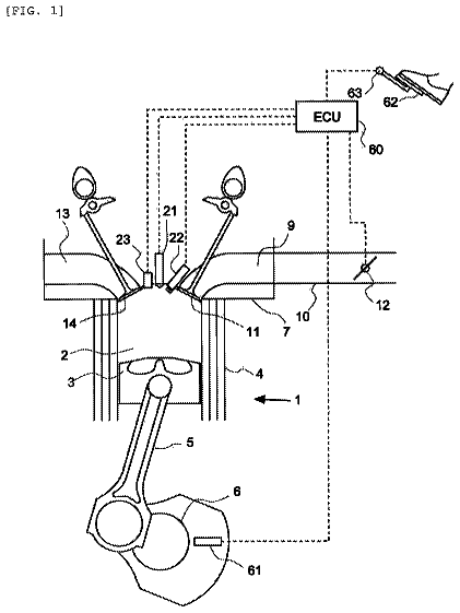
FIG. 1 is a functional block diagram of an example engine system according to the present disclosure;
FIG. 2 is a functional block diagram of an example engine control system according to the present disclosure;
FIG. 3 is a functional block diagram of an example air control module according to the present disclosure;
FIG. 4 is a functional block diagram of an example target air per cylinder (APC) module according to the present disclosure; and
FIG. 5 includes a flowchart depicting an example method of controlling a throttle valve according to the present disclosure.
In the drawings, reference numbers may be reused to identify similar and/or identical elements.
Detailed description
Internal combustion engines combust an air and fuel mixture within cylinders to generate torque. Under some circumstances, an engine control module (ECM) may deactivate one or more cylinders of the engine. The ECM may deactivate one or more cylinders, for example, to decrease fuel consumption when the engine can achieve a torque request using less than all of the cylinders of the engine. The ECM may activate one or more deactivated cylinders, for example, when the torque request increases.
Airflow into the engine may vary when one or more cylinders are activated or deactivated. The ECM of the present disclosure determines a target mass air flowrate (MAF) through a throttle valve for use when one or more cylinders are activated or deactivated. The ECM controls opening of a throttle valve of the engine based on the target MAF. Controlling the throttle valve based on the target MAF may provide smoother air per cylinder (APC) conditions and, therefore smoother engine torque output, while the cylinder(s) are activated or deactivated.
Referring now to FIG. 1 , a functional block diagram of an example engine system 100 is presented. The engine system 100 includes an engine 102 that combusts an air/fuel mixture to produce drive torque for a vehicle based on driver input from a driver input module 104 . Air is drawn into an intake manifold 110 through a throttle valve 112 . For example only, the throttle valve 112 may include a butterfly valve having a rotatable blade. An engine control module (ECM) 114 controls a throttle actuator module 116 , which regulates opening of the throttle valve 112 to control the amount of air drawn into the intake manifold 110 .
Air from the intake manifold 110 is drawn into cylinders of the engine 102 . While the engine 102 may include multiple cylinders, for illustration purposes a single representative cylinder 118 is shown. For example only, the engine 102 may include 2, 3, 4, 5, 6, 8, 10, and/or 12 cylinders. The ECM 114 may instruct a cylinder actuator module 120 to selectively deactivate some of the cylinders, which may improve fuel economy under certain engine operating conditions.
The engine 102 may operate using a four-stroke cycle. The four strokes, described below, may be referred to as the intake stroke, the compression stroke, the combustion stroke, and the exhaust stroke. During each revolution of a crankshaft (not shown), two of the four strokes occur within the cylinder 118 . Therefore, two crankshaft revolutions are necessary for the cylinder 118 to experience all four of the strokes.
During the intake stroke, air from the intake manifold 110 is drawn into the cylinder 118 through an intake valve 122 . The ECM 114 controls a fuel actuator module 124 , which regulates fuel injection to achieve a target air/fuel ratio. Fuel may be injected into the intake manifold 110 at a central location or at multiple locations, such as near the intake valve 122 of each of the cylinders. In various implementations (not shown), fuel may be injected directly into the cylinders or into mixing chambers associated with the cylinders. The fuel actuator module 124 may halt injection of fuel to cylinders that are deactivated.
The injected fuel mixes with air and creates an air/fuel mixture in the cylinder 118 . During the compression stroke, a piston (not shown) within the cylinder 118 compresses the air/fuel mixture. While not shown, the engine 102 may be a compression-ignition engine, in which case compression within the cylinder 118 ignites the air/fuel mixture. Alternatively, as shown, the engine 102 may be a spark-ignition engine, in which case a spark actuator module 126 energizes a spark plug 128 in the cylinder 118 based on a signal from the ECM 114 , which ignites the air/fuel mixture. The timing of the spark may be specified relative to the time when the piston is at its topmost position, referred to as top dead center (TDC).
The spark actuator module 126 may be controlled by a timing signal specifying how far before or after TDC to generate the spark. Because piston position is directly related to crankshaft rotation, operation of the spark actuator module 126 may be synchronized with crankshaft angle. The spark actuator module 126 may halt provision of spark to deactivated cylinders. Generating spark may be referred to as a firing event. The spark actuator module 126 may have the ability to vary the timing of the spark for each firing event. The spark actuator module 126 may vary the spark timing for a next firing event when the spark timing is changed between a last firing event and the next firing event.
During the combustion stroke, the combustion of the air/fuel mixture drives the piston away from TDC, thereby driving the crankshaft. The combustion stroke may be defined as the time between the piston reaching TDC and the time at which the piston reaches bottom dead center (BDC). During the exhaust stroke, the piston begins moving away from BDC and expels the byproducts of combustion through an exhaust valve 130 . The byproducts of combustion are exhausted from the vehicle via an exhaust system 134 .
The intake valve 122 may be controlled by an intake camshaft 140 , while the exhaust valve 130 may be controlled by an exhaust camshaft 142 . In various implementations, multiple intake camshafts (including the intake camshaft 140 ) may control multiple intake valves (including the intake valve 122 ) for the cylinder 118 and/or may control the intake valves (including the intake valve 122 ) of multiple banks of cylinders (including the cylinder 118 ). Similarly, multiple exhaust camshafts (including the exhaust camshaft 142 ) may control multiple exhaust valves for the cylinder 118 and/or may control exhaust valves (including the exhaust valve 130 ) for multiple banks of cylinders (including the cylinder 118 ). The cylinder actuator module 120 may deactivate the cylinder 118 by disabling opening of the intake valve 122 and/or the exhaust valve 130 . In various other implementations, the intake valve 122 and/or the exhaust valve 130 may be controlled by devices other than camshafts, such as camless valve actuators.
The time when the intake valve 122 is opened may be varied with respect to piston TDC by an intake cam phaser 148 . The time when the exhaust valve 130 is opened may be varied with respect to piston TDC by an exhaust cam phaser 150 . A phaser actuator module 158 may control the intake cam phaser 148 and the exhaust cam phaser 150 based on signals from the ECM 114 . When implemented, variable valve lift (not shown) may also be controlled by the phaser actuator module 158 .
The engine system 100 may include a boost device that provides pressurized air to the intake manifold 110 . For example, FIG. 1 shows a turbocharger including a hot turbine 160 - 1 that is powered by hot exhaust gases flowing through the exhaust system 134 . The turbocharger also includes a cold air compressor 160 - 2 that is driven by the turbine 160 - 1 . The compressor 160 - 2 compresses air leading into the throttle valve 112 . In various implementations, a supercharger (not shown), driven by the crankshaft, may compress air from the throttle valve 112 and deliver the compressed air to the intake manifold 110 .
A wastegate 162 may allow exhaust to bypass the turbine 160 - 1 , thereby reducing the boost (the amount of intake air compression) provided by the turbocharger. The ECM 114 may control the turbocharger via a boost actuator module 164 . The boost actuator module 164 may modulate the boost of the turbocharger by controlling opening of the wastegate 162 . In various implementations, multiple turbochargers may be controlled by the boost actuator module 164 . The turbocharger may have variable geometry, which may be controlled by the boost actuator module 164 .
An intercooler (not shown) may dissipate some of the heat contained in the compressed air charge, which is generated as the air is compressed. The compressed air charge may also have absorbed heat from components of the exhaust system 134 . Although shown separated for purposes of illustration, the turbine 160 - 1 and the compressor 160 - 2 may be attached to each other, placing intake air in close proximity to hot exhaust.
The engine system 100 may include an exhaust gas recirculation (EGR) valve 170 , which selectively redirects exhaust gas back to the intake manifold 110 . The EGR valve 170 may be located upstream of the turbocharger's turbine 160 - 1 . The EGR valve 170 may be controlled by an EGR actuator module 172 .
The engine system 100 may measure the rotational speed of the crankshaft in revolutions per minute (RPM) using an RPM sensor 180 . The speed of the crankshaft may be referred to as an engine speed. The temperature of the engine coolant may be measured using an engine coolant temperature (ECT) sensor 182 . The ECT sensor 182 may be located within the engine 102 or at other locations where the coolant is circulated, such as a radiator (not shown).
The pressure within the intake manifold 110 may be measured using a manifold absolute pressure (MAP) sensor 184 . In various implementations, engine vacuum, which is the difference between ambient air pressure and the pressure within the intake manifold 110 , may be measured. The mass flow rate of air flowing into the intake manifold 110 may be measured using a mass air flow (MAF) sensor 186 . In various implementations, the MAF sensor 186 may be located in a housing that also includes the throttle valve 112 .
The throttle actuator module 116 may monitor the position of the throttle valve 112 using one or more throttle position sensors (TPS) 190 . The ambient temperature of air being drawn into the engine 102 may be measured using an intake air temperature (IAT) sensor 192 . The engine system 100 may also include one or more other sensors. The ECM 114 may use signals from the sensors to make control decisions for the engine system 100 .
The ECM 114 may communicate with a transmission control module 194 to coordinate shifting gears in a transmission (not shown). For example, the ECM 114 may reduce engine torque during a gear shift. The ECM 114 may communicate with a hybrid control module 196 to coordinate operation of the engine 102 and an electric motor 198 .
The electric motor 198 may also function as a generator, and may be used to produce electrical energy for use by vehicle electrical systems and/or for storage in a battery. In various implementations, various functions of the ECM 114 , the transmission control module 194 , and the hybrid control module 196 may be integrated into one or more modules.
Each system that varies an engine parameter may be referred to as an actuator. Each system receives a target actuator value. For example, the throttle actuator module 116 may be referred to as an actuator, and a target throttle opening (e.g., area) may be referred to as the target actuator value. In the example of FIG. 1 , the throttle actuator module 116 achieves the target throttle opening by adjusting an angle of the blade of the throttle valve 112 .
Similarly, the spark actuator module 126 may be referred to as an actuator, while the corresponding target actuator value may be a target spark timing relative to piston TDC. Other actuators may include the cylinder actuator module 120 , the fuel actuator module 124 , the phaser actuator module 158 , the boost actuator module 164 , and the EGR actuator module 172 . For these actuators, the target actuator values may include target number of activated cylinders, target fueling parameters, target intake and exhaust cam phaser angles, target wastegate duty cycle, and target EGR valve opening area, respectively. The ECM 114 may generate the target actuator values to cause the engine 102 to generate a target engine output torque.
Referring now to FIG. 2 , a functional block diagram of an example engine control system is presented. An example implementation of the ECM 114 includes a driver torque module 202 , an axle torque arbitration module 204 , and a propulsion torque arbitration module 206 . The ECM 114 may include a hybrid optimization module 208 . The ECM 114 also includes a reserves/loads module 220 , a torque requesting module 224 , an air control module 228 , a spark control module 232 , a cylinder control module 236 , and a fuel control module 240 . The ECM 114 also includes an air per cylinder (APC) torque estimation module 244 , a MAP torque estimation module 246 , a boost control module 248 , a phaser control module 252 , and an EGR control module 253 .
The driver torque module 202 may determine a driver torque request 254 based on a driver input 255 from the driver input module 104 . The driver input 255 may be based on, for example, a position of an accelerator pedal and a position of a brake pedal. The driver input 255 may also be based on cruise control, which may be an adaptive cruise control system that varies vehicle speed to maintain a predetermined following distance. The driver torque module 202 may store one or more mappings of accelerator pedal position to target torque and may determine the driver torque request 254 based on a selected one of the mappings.
An axle torque arbitration module 204 arbitrates between the driver torque request 254 and other axle torque requests 256 . Axle torque (torque at the wheels) may be produced by various sources including an engine and/or an electric motor. For example, the axle torque requests 256 may include a torque reduction requested by a traction control system when positive wheel slip is detected. Positive wheel slip occurs when axle torque overcomes friction between the wheels and the road surface, and the wheels begin to slip against the road surface. The axle torque requests 256 may also include a torque increase request to counteract negative wheel slip, where a tire of the vehicle slips in the other direction with respect to the road surface because the axle torque is negative.
The axle torque requests 256 may also include brake management requests and vehicle over-speed torque requests. Brake management requests may reduce axle torque to ensure that the axle torque does not exceed the ability of the brakes to hold the vehicle when the vehicle is stopped. Vehicle over-speed torque requests may reduce the axle torque to prevent the vehicle from exceeding a predetermined speed. The axle torque requests 256 may also be generated by vehicle stability control systems.
The axle torque arbitration module 204 outputs a predicted torque request 257 and an immediate torque request 258 based on the results of arbitrating between the received torque requests 254 and 256 . As described below, the predicted and immediate torque requests 257 and 258 from the axle torque arbitration module 204 may selectively be adjusted by other modules of the ECM 114 before being used to control the actuators of the engine system 100 .
In general terms, the immediate torque request 258 is the amount of currently target axle torque, while the predicted torque request 257 is the amount of axle torque that may be needed on short notice. The ECM 114 controls the engine system 100 to produce an axle torque equal to the immediate torque request 258 . However, different combinations of actuator values may result in the same axle torque. The ECM 114 may therefore adjust the target actuator values to enable a faster transition to the predicted torque request 257 , while still maintaining the axle torque at the immediate torque request 258 .
In various implementations, the predicted torque request 257 may be set based on the driver torque request 254 . The immediate torque request 258 may be set to less than the predicted torque request 257 under some circumstances, such as when the driver torque request 254 is causing wheel slip on an icy surface. In such a case, a traction control system (not shown) may request a reduction via the immediate torque request 258 , and the ECM 114 reduces the engine torque output to the immediate torque request 258 . However, the ECM 114 performs the reduction so the engine system 100 can quickly resume producing the predicted torque request 257 once the wheel slip stops.
In general terms, the difference between the immediate torque request 258 and the (generally higher) predicted torque request 257 can be referred to as a torque reserve. The torque reserve may represent the amount of additional torque (above the immediate torque request 258 ) that the engine system 100 can begin to produce with minimal delay. Fast engine actuators are used to increase or decrease current axle torque with minimal delay. As described in more detail below, fast engine actuators are defined in contrast with slow engine actuators.
In various implementations, fast engine actuators are capable of varying axle torque within a range, where the range is established by the slow engine actuators. The upper limit of the range is the predicted torque request 257 , while the lower limit of the range is limited by the torque (varying) capacity of the fast actuators. For example only, fast actuators may only be able to reduce axle torque by a first amount, where the first amount is a measure of the torque capacity of the fast actuators. The first amount may vary based on engine operating conditions set by the slow engine actuators.
When the immediate torque request 258 is within the range, fast engine actuators can be controlled to cause the axle torque to be equal to the immediate torque request 258 . When the ECM 114 requests the predicted torque request 257 to be output, the fast engine actuators can be controlled to vary the axle torque to the top of the range, which is the predicted torque request 257 .
In general terms, fast engine actuators can change the axle torque more quickly than slow engine actuators. Slow actuators may respond more slowly to changes in their respective actuator values than fast actuators do. For example, a slow actuator may include mechanical components that require time to move from one position to another in response to a change in actuator value. A slow actuator may also be characterized by the amount of time it takes for the axle torque to begin to change once the slow actuator begins to implement the changed actuator value. Generally, this amount of time will be longer for slow actuators than for fast actuators. In addition, even after beginning to change, the axle torque may take longer to fully respond to a change in a slow actuator.
For example only, the ECM 114 may set actuator values for slow actuators to values that would enable the engine system 100 to produce the predicted torque request 257 if the fast actuators were set to appropriate values. Meanwhile, the ECM 114 may set target actuator values for fast actuators to values that, given the slow actuator values, cause the engine system 100 to produce the immediate torque request 258 instead of the predicted torque request 257 .
The fast actuators therefore cause the engine system 100 to produce the immediate torque request 258 . When the ECM 114 decides to transition the axle torque from the immediate torque request 258 to the predicted torque request 257 , the ECM 114 changes the target actuator values for one or more fast actuators to values that correspond to the predicted torque request 257 . Because the target actuator values for the slow actuators have already been set based on the predicted torque request 257 , the engine system 100 is able to produce the predicted torque request 257 after only the (minimal) delay imposed by the fast actuators. In other words, the longer delay that would otherwise result from changing axle torque using slow actuators is avoided.
For example only, in a spark-ignition engine, spark timing may be a fast actuator value, while throttle opening may be a slow actuator value. Spark-ignition engines may combust fuels including, for example, gasoline and ethanol, by applying a spark. By contrast, in a compression-ignition engine, fuel flow may be a fast actuator value, while throttle opening may be used as an actuator value for engine characteristics other than torque. Compression-ignition engines may combust fuels including, for example, diesel fuel, via compression.
When the engine 102 is a spark-ignition engine, the spark actuator module 126 may be a fast actuator and the throttle actuator module 116 may be a slow actuator. After receiving a new target actuator value, the spark actuator module 126 may be able to change spark timing for the following firing event. When the spark timing (also called spark advance) for a firing event is set to an optimum value, a maximum amount of torque may be produced in the combustion stroke immediately following the firing event. However, a spark timing deviating from the optimum value may reduce the amount of torque produced in the combustion stroke. Therefore, the spark actuator module 126 may be able to vary engine output torque as soon as the next firing event occurs by varying spark timing. For example only, a table of optimum spark timings corresponding to different engine operating conditions may be determined during a calibration phase of vehicle design, and the optimum value is selected from the table based on current engine operating conditions.
By contrast, changes in throttle opening take longer to affect engine output torque. The throttle actuator module 116 changes the throttle opening by adjusting the angle of the blade of the throttle valve 112 . Therefore, once a new actuator value is received, there is a mechanical delay as the throttle valve 112 moves from its previous position to a new position based on the new target actuator value. In addition, air flow changes based on the throttle opening are subject to air transport delays in the intake manifold 110 . Further, increased air flow in the intake manifold 110 is not realized as an increase in engine output torque until the cylinder 118 receives additional air in the next intake stroke, compresses the additional air, and commences the combustion stroke.
Using these actuators as an example, a torque reserve can be created by setting the throttle opening to a value that would allow the engine 102 to produce the predicted torque request 257 . Meanwhile, the spark timing can be set based on the immediate torque request 258 , which is less than the predicted torque request 257 . Although the throttle opening generates enough air flow for the engine 102 to produce the predicted torque request 257 , the spark timing is retarded (which reduces torque) based on the immediate torque request 258 . The engine output torque will therefore be equal to the immediate torque request 258 .
When additional torque is needed, the spark timing can be set based on the predicted torque request 257 or a torque between the predicted and immediate torque requests 257 and 258 . By the following firing event, the spark actuator module 126 may return the spark timing to an optimum value, which allows the engine 102 to produce the full engine output torque achievable with the air flow already present. The engine output torque may therefore be quickly increased to the predicted torque request 257 without experiencing delays from changing the throttle opening.
The axle torque arbitration module 204 may output the predicted torque request 257 and the immediate torque request 258 to a propulsion torque arbitration module 206 . In various implementations, the axle torque arbitration module 204 may output the predicted and immediate torque requests 257 and 258 to the hybrid optimization module 208 .
The hybrid optimization module 208 may determine how much torque should be produced by the engine 102 and how much torque should be produced by the electric motor 198 . The hybrid optimization module 208 then outputs modified predicted and immediate torque requests 259 and 260 , respectively, to the propulsion torque arbitration module 206 . In various implementations, the hybrid optimization module 208 may be implemented in the hybrid control module 196 .
The predicted and immediate torque requests received by the propulsion torque arbitration module 206 are converted from an axle torque domain (torque at the wheels) into a propulsion torque domain (torque at the crankshaft). This conversion may occur before, after, as part of, or in place of the hybrid optimization module 208 .
The propulsion torque arbitration module 206 arbitrates between propulsion torque requests 290 , including the converted predicted and immediate torque requests. The propulsion torque arbitration module 206 generates an arbitrated predicted torque request 261 and an arbitrated immediate torque request 262 . The arbitrated torque requests 261 and 262 may be generated by selecting a winning request from among received torque requests. Alternatively or additionally, the arbitrated torque requests may be generated by modifying one of the received requests based on another one or more of the received torque requests.
For example, the propulsion torque requests 290 may include torque reductions for engine over-speed protection, torque increases for stall prevention, and torque reductions requested by the transmission control module 194 to accommodate gear shifts. The propulsion torque requests 290 may also result from clutch fuel cutoff, which reduces the engine output torque when the driver depresses the clutch pedal in a manual transmission vehicle to prevent a flare (rapid rise) in engine speed.
The propulsion torque requests 290 may also include an engine shutoff request, which may be initiated when a critical fault is detected. For example only, critical faults may include detection of vehicle theft, a stuck starter motor, electronic throttle control problems, and unexpected torque increases. In various implementations, when an engine shutoff request is present, arbitration selects the engine shutoff request as the winning request. When the engine shutoff request is present, the propulsion torque arbitration module 206 may output zero as the arbitrated predicted and immediate torque requests 261 and 262 .
In various implementations, an engine shutoff request may simply shut down the engine 102 separately from the arbitration process. The propulsion torque arbitration module 206 may still receive the engine shutoff request so that, for example, appropriate data can be fed back to other torque requestors. For example, all other torque requestors may be informed that they have lost arbitration.
The reserves/loads module 220 receives the arbitrated predicted and immediate torque requests 261 and 262 . The reserves/loads module 220 may adjust the arbitrated predicted and immediate torque requests 261 and 262 to create a torque reserve and/or to compensate for one or more loads. The reserves/loads module 220 then outputs adjusted predicted and immediate torque requests 263 and 264 to the torque requesting module 224 .
For example only, a catalyst light-off process or a cold start emissions reduction process may require retarded spark timing. The reserves/loads module 220 may therefore increase the adjusted predicted torque request 263 above the adjusted immediate torque request 264 to create retarded spark for the cold start emissions reduction process. In another example, the air/fuel ratio of the engine and/or the mass air flow may be directly varied, such as by diagnostic intrusive equivalence ratio testing and/or new engine purging. Before beginning these processes, a torque reserve may be created or increased to quickly offset decreases in engine output torque that result from leaning the air/fuel mixture during these processes.
The reserves/loads module 220 may also create or increase a torque reserve in anticipation of a future load, such as power steering pump operation or engagement of an air conditioning (A/C) compressor clutch. The reserve for engagement of the A/C compressor clutch may be created when the driver first requests air conditioning. The reserves/loads module 220 may increase the adjusted predicted torque request 263 while leaving the adjusted immediate torque request 264 unchanged to produce the torque reserve. Then, when the A/C compressor clutch engages, the reserves/loads module 220 may increase the adjusted immediate torque request 264 by the estimated load of the A/C compressor clutch.
The torque requesting module 224 receives the adjusted predicted and immediate torque requests 263 and 264 . The torque requesting module 224 determines how the adjusted predicted and immediate torque requests 263 and 264 will be achieved. The torque requesting module 224 may be engine type specific. For example, the torque requesting module 224 may be implemented differently or use different control schemes for spark-ignition engines versus compression-ignition engines.
In various implementations, the torque requesting module 224 may define a boundary between modules that are common across all engine types and modules that are engine type specific. For example, engine types may include spark-ignition and compression-ignition. Modules prior to the torque requesting module 224 , such as the propulsion torque arbitration module 206 , may be common across engine types, while the torque requesting module 224 and subsequent modules may be engine type specific.
For example, in a spark-ignition engine, the torque requesting module 224 may vary the opening of the throttle valve 112 as a slow actuator that allows for a wide range of torque control. The torque requesting module 224 may disable cylinders using the cylinder actuator module 120 , which also provides for a wide range of torque control, but may also be slow and may involve drivability and emissions concerns. The torque requesting module 224 may use spark timing as a fast actuator. However, spark timing may not provide as much range of torque control. In addition, the amount of torque control possible with changes in spark timing (referred to as spark reserve capacity) may vary as air flow changes.
In various implementations, the torque requesting module 224 may generate an air torque request 265 based on the adjusted predicted torque request 263 . The air torque request 265 may be equal to the adjusted predicted torque request 263 , setting air flow so that the adjusted predicted torque request 263 can be achieved by changes to other (e.g., fast) actuators.
Target actuator values for airflow controlling actuators may be determined based on the air torque request 265 . For example only, the air control module 228 (see also FIG. 3 ) may determine a target manifold absolute pressure (MAP) 266 , a target throttle opening (e.g., area) 267 , a second target air per cylinder (APC 2 ) 268 , and a third target APC (APC 3 ) 291 based on the air torque request 265 . Determination of the second and third target APCs 268 and 291 are discussed further below.
The description continues in the full USPTO document.
 Lapsed, fee not paid7 drawings

