 Lapsed, fee not paid7 drawings
Medical Devices · US 9,797,764 B2
Light enhanced flow tube
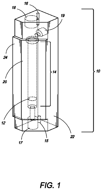
An improved fluid flow gauging device includes a light enhanced acrylic block flow tube to optimize visualization of pressure readings.
US 9,801,537 B2 · Assignee: SONY CORPORATION · Inventors: Kobayashi; Seiji
Sheet 1 of 4 from the published document. All sheets in the USPTO PDF
An eye fundus image photographing device and method that can acquire images of higher quality. The eye fundus image photographing device photographs a wide-angle eye fundus image on an appropriate exposure condition with respect to a peripheral area different from an optic disk region of an eye fundus area and detects the optic disk region from the wide-angle eye fundus image. Moreover, based on the detection result of the optic disk region, the eye fundus image photographing device photographs a narrow-angle eye fundus image which assumes an area of the optic disk region as an object, on an appropriate exposure condition with respect to the area of the optic disk region. Further, the eye fundus image photographing device generates a synthetic eye fundus image of a high dynamic range by synthesizing the wide-angle eye fundus image and the narrow-angle eye fundus image.
For example, in an eye fundus camera that photographs patient's eye fundus image in the checkup or the ophthalmologic examination, a photographing function in a high dynamic range is desired to stably acquire an eye fundus image of high quality. In an eye fundus image assuming person's eye fundus as an object, the reflection of a light source is strong and blown-out highlights are likely to be caused in an optic disk region from which retinal nerves come out in a bundled manner, and the reflection intensity is weak and therefore blocked-up shadows are likely to be caused in a macular region corresponding to the central fovea. To perform photographing so as not to cause the blown-out highlights in the optic disk region, the exposure setting at the time of the photographing has to be optimized and the photographer's skill is demanded. Moreover, even if photographing is performed so as not
All 4 drawing sheets from the published document, cropped to the drawing.
What the patent claimed, word for word. All of it is now free to use.
The present technology relates to an image processing device and method, an eye fundus image processing device, an image photographing method and an eye fundus image photographing device and method. Especially, the present technology relates to an image processing device and method, an eye fundus image processing device, an image photographing method and an eye fundus image photographing device and method that can acquire images of higher quality.
This application claims priority to Japanese Priority Patent Application JP 2013-163781 filed on Aug. 7, 2013, the entire contents of which are incorporated herein by reference.
For example, in an eye fundus camera that photographs patient's eye fundus image in the checkup or the ophthalmologic examination, a photographing function in a high dynamic range is desired to stably acquire an eye fundus image of high quality.
In an eye fundus image assuming person's eye fundus as an object, the reflection of a light source is strong and blown-out highlights are likely to be caused in an optic disk region from which retinal nerves come out in a bundled manner, and the reflection intensity is weak and therefore blocked-up shadows are likely to be caused in a macular region corresponding to the central fovea.
To perform photographing so as not to cause the blown-out highlights in the optic disk region, the exposure setting at the time of the photographing has to be optimized and the photographer's skill is demanded. Moreover, even if photographing is performed so as not to cause the blown-out highlights in the optic disk region, the macular region and the peripheral region may be filled with black and become difficult to be diagnosed. In view of such state, a photographing function in a high dynamic range is desired for an eye fundus camera.
Therefore, as a technique to acquire an eye fundus image of a high dynamic range, there is suggested a method of defining the suitable light quantity in each region on the basis of the first photographing result (for example, see JP 2011-31027 A).
In this method, first, the light quantities of the optic disk region and the periphery are acquired by the first photographing, and, in the second photographing, photographing is performed by a suitable light quantity with respect to an area of the optic disk region which is defined by the first photographing and the area of the optic disk region is extracted from an acquired image.
Further, in the third photographing, photographing is performed by a suitable light quantity with respect to a peripheral area near the optic disk region which is defined by the first photographing, and the peripheral area is extracted from an acquired image. Moreover, the area of the optic disk region and the peripheral area which are acquired as above are synthesized to acquire one eye fundus image of a high dynamic range. CITATION LIST Patent Literature
PTL 1: JP 2011-31027 A SUMMARY OF INVENTION Technical Problem
However, in the related art described above, it is difficult to acquire an eye fundus image of high quality.
For example, in a case where an eye fundus image is photographed by a non-mydriatic camera, it is considered that miosis occurs during three times of photographing. Especially in the above-mentioned technique, since the peripheral area is photographed in the third photographing, when the miosis is caused, the image quality of the image of the peripheral area is deteriorated by the influence.
The present technology is made in view of such a situation, and it is possible to acquire an image of higher quality. Solution to Problem
An image processing device according to a first aspect of the present technology includes: a detection unit configured to detect a narrow-angle area of a wide-angle image, wherein the wide-angle image was generated using a first exposure condition, the first exposure condition based on a first area of the wide-angle image, different from the narrow-angle area; a control unit configured to determine a second exposure condition for the narrow-angle area; and an image synthesis unit configured to generate a synthetic image by synthesizing a narrow-angle image and the wide-angle image, wherein the narrow-angle image has a narrower angle of view than the wide-angle image and was generated using the second exposure condition.
The image synthesis unit can generate the synthesis image by synthesizing a plurality of narrow-angle images that are continuously photographed and the wide-angle image.
The image synthesis unit can perform motion compensation on the plurality of narrow-angle images and synthesize the plurality of narrow-angle images acquired by the motion compensation and the wide-angle image.
The control unit can determine a pixel area in order to photograph the narrow-angle image using the pixel area and based on a detection of the narrow-angle area.
The control unit can control a light source that outputs illumination light irradiated to the narrow-angle area or a photographing unit that photographs the narrow-angle image based on the second exposure condition with respect to the narrow-angle area.
The control unit can control a light source such that the narrow-angle area is illuminated by equal light outputs from the light source when the wide-angle image is photographed and when the narrow-angle image is photographed.
The second exposure condition is set such that a pixel of the narrow-angle area in the narrow-angle image is not saturated.
According to the first aspect of the present technology, a narrow-angle area is detected from a wide-angle image, wherein the wide-angle image was generated using a first exposure condition, the first exposure condition based on a first area of the wide-angle image, different from the narrow-angle area, a second exposure condition for the narrow-angle area is determined, and a synthetic image is generated by synthesizing a narrow-angle image and a wide-angle image, wherein the narrow-angle image has a narrower angle of view than the wide-angle image and was generated for the narrow-angle area using the second exposure condition.
An eye fundus image processing device according to a second aspect of the present technology includes: a detection unit configured to detect a narrow-angle area of an eye fundus from a wide-angle image, wherein the wide-angle image was generated using a first exposure condition, the first exposure condition based on a first area of the eye fundus, different from the narrow-angle area; a control unit configured to determine a second exposure condition for the narrow-angle area of the eye fundus; and an image synthesis unit configured to generate a synthetic image by synthesizing a narrow-angle image and the wide-angle image, wherein the narrow-angle image has a narrower angle of view than the wide-angle image and was generated for the narrow-angle area of the eye fundus using the second exposure condition.
The narrow-angle area of the eye fundus can be an area of an optic disk.
According to the second aspect of the present technology, a narrow-angle area of an eye fundus is detected from a wide-angle image, wherein the wide-angle image was generated using a first exposure condition, the first exposure condition based on a first area of the eye fundus, different from the narrow-angle area, a second exposure condition is determined for the narrow-angle area of the eye fundus, and a synthetic image is generated by synthesizing a narrow-angle image and the wide-angle image, wherein the narrow-angle image has a narrower angle of view than the wide-angle image and was generated for the narrow-angle area of the eye fundus using the second exposure condition.
An image processing method according to a third aspect of the present technology includes detecting a narrow-angle area of a wide-angle image, wherein the wide-angle image was generated using a first exposure condition, the first exposure condition based on a first area of the wide-angle image, different from the narrow-angle area, determining a second exposure condition for the narrow-angle area, and generating a synthetic image by synthesizing a narrow-angle image and the wide-angle image, wherein the narrow-angle image has a narrower angle of view than the wide-angle image and was generated for the narrow-angle area using the second exposure condition.
According to the third aspect of the present technology, a narrow-angle area is detected from a wide-angle image, wherein the wide-angle image was generated using a first exposure condition, the first exposure condition based on a first area of the wide-angle image, different from the narrow-angle area, a second exposure condition is determined for the narrow-angle area, and a synthetic image is generated by synthesizing a narrow-angle image and the wide-angle image, wherein the narrow-angle image has a narrower angle of view than the wide-angle image and was generated for the narrow-angle area using the second exposure condition.
An image photographing method according to a fourth aspect of the present technology includes photographing a wide-angle image using a first exposure condition based on a first area of the wide-angle image, determining a second exposure condition for a narrow-angle area, different from the first area, based on the wide-angle image, and photographing a narrow-angle image having a narrower angle of view than the wide-angle image, based on the second exposure condition and the narrow-angle area.
In the image photographing method, it is possible to detect the narrow-angle area based on the wide-angle image and determine the second exposure condition with respect to the narrow-angle area based on a detection result of the narrow-angle area.
Photographing the narrow-angle image comprises continuously photographing a plurality of narrow-angle images.
The narrow-angle image can be photographed using a pixel area of a photographing unit, the pixel area determined based on the detection result of the narrow-angle area.
A light source can be controlled such that the narrow-angle area is illuminated by equal light outputs from the light source when photographing the wide-angle image and when photographing the narrow-angle image.
The second exposure condition can be set such that a pixel of the narrow-angle area in the narrow-angle image is not saturated.
According to the fourth aspect of the present technology, photographing is performed to photograph a wide-angle image using a first exposure condition based on a first area of the wide-angle image, a second exposure condition is determined for a narrow-angle area, different from the first area, based on the wide-angle image, and photographing is performed to photograph a narrow-angle image having a narrower angle of view than the wide-angle image, based on the second exposure condition and the narrow-angle area.
The eye fundus image photographing method according to a fifth aspect of the present technology includes photographing a wide-angle image using a first exposure condition based on a first area of the wide-angle image, determining a second exposure condition for a narrow-angle area of an eye fundus, different from the first area, based on the wide-angle image, and photographing a narrow-angle image having a narrower angle of view than the wide-angle image, based on the second exposure condition and the narrow-angle area of the eye fundus.
The narrow-angle area of the eye fundus can be an area of an optic disk.
According to the fifth aspect of the present technology, photographing is performed to photograph a wide-angle image using a first exposure condition based on a first area the wide-angle image, a second exposure condition for a narrow-angle area of an eye fundus, different from the first area, is determined based on the wide-angle image, and photographing is performed to photograph a narrow-angle image having a narrower angle of view than the wide-angle image, based on the second exposure condition and the narrow-angle area of the eye fundus.
An eye fundus image photographing device according to a sixth aspect of the present technology includes: a photographing unit configured to photograph a wide-angle image using a first exposure condition based on a first area of an eye fundus, and photograph a narrow-angle image, having a narrower angle of view than the wide-angle image, using a second exposure condition based on a narrow-angle area of the eye fundus, a detection unit configured to detect the narrow-angle area of the eye fundus from the wide-angle image based on the wide-angle image, a control unit configured to determine the second exposure condition with respect to the narrow-angle area of the eye fundus based on the detection of the narrow-angle area of the eye fundus, and an image synthesis unit configured to generate a synthetic image by synthesizing the narrow-angle image and the wide-angle image.
According to the sixth aspect of the present technology, a wide-angle image is photographed using a first exposure condition based on a first area of an eye fundus, a narrow-angle image is photographed having a narrower angle of view than the wide-angle image using a second exposure condition based on a narrow-angle area of the eye fundus, the narrow-angle area of the eye fundus is detected from the wide-angle image based on the wide-angle image, the second exposure condition with respect to the narrow-angle area of the eye fundus is determined based on the detection of the narrow-angle area of the eye fundus, and a synthetic image is generated by synthesizing the narrow-angle image and the wide-angle image. Advantageous Effects of Invention
According to first to sixth aspects of the present technology, it is possible to acquire an image of higher quality.
FIG. 1 is a diagram to describe the outline of the present technology.
FIG. 2 is a diagram illustrating a configuration example of an eye fundus image photographing device.
FIG. 3 is a flowchart to describe image generation processing.
FIG. 4 is a diagram illustrating a configuration example of a computer.
In the following, embodiments to which the present technology applies are described with reference to the drawings. First Embodiment
<Outline of the Present Technology>
First, the outline of the present technology is described.
According to an embodiment of the present technology, by synthesizing an image of the entire eye fundus photographed under high illumination intensity and an image of the optic disk region of the eye fundus photographed under low illumination intensity, it is possible to acquire an eye fundus image of high quality with a wide dynamic range.
Specifically, in an eye fundus image photographing device to which the present technology applies, for example, as the first photographing processing as illustrated in FIG. 1 , an eye fundus area that is an object is photographed under high illumination intensity and wide-angle eye fundus image WP 11 is acquired as a result.
Wide-angle eye fundus image WP 11 is an eye fundus image photographed with a wide angle of view. In this example, wide-angle eye fundus image WP 11 includes optic disk region V 11 and macular region V 12 . Generally, it is known that blown-out highlights are likely to occur in optic disk region V 11 and blocked-up shadows are likely to occur in macular region V 12 .
In the first photographing processing, the photographing is performed on exposure conditions on which blown-out highlights and blocked-up shadows are not caused in other areas than optic disk region V 11 such as macular region V 12 , that is, in the peripheral area of optic disk region V 11 (which may also be referred to as “peripheral area” below). That is, the photographing is performed on adaptive exposure conditions with respect to the peripheral area. By this means, it is possible to acquire wide-angle eye fundus image WP 11 in which the signal to noise ratio (SN ratio) of the peripheral area is high and it is possible to sufficiently observe the peripheral area.
Moreover, when wide-angle eye fundus image WP 11 is acquired, the area of optic disk region V 11 is detected from wide-angle eye fundus image WP 11 in the eye fundus image photographing device, and, based on the detection result, exposure conditions in the second photographing processing are decided.
For example, since wide-angle eye fundus image WP 11 is photographed on the appropriate exposure conditions with respect to the peripheral area, blown-out highlights are supposed to occur in the area of optic disk region V 11 . Therefore, by detecting a high brightness area on wide-angle eye fundus image WP 11 in the eye fundus image photographing device, the area of optic disk region V 11 is detected.
Moreover, the exposure conditions in the second photographing processing are set to appropriate exposure conditions with respect to the area of optic disk region V 11 , on which blown-out highlights and blocked-up shadows are not caused in optic disk region V 11 . That is, exposure conditions on which it is possible to sufficiently observe the area of optic disk region V 11 are set.
When the exposure conditions are decided, an area including optic disk region V 11 is photographed under low illumination intensity as the second photographing processing. In this example, an eye fundus area corresponding to area R 11 on wide-angle eye fundus image WP 11 is continuously photographed at a high frame rate on the decided exposure conditions.
By this means, four narrow-angle eye fundus images NP 11 - 1 to NP 11 - 4 are acquired. Here, in the following, in a case where narrow-angle eye fundus images NP 11 - 1 to NP 11 - 4 do not have to be especially distinguished, they may be simply referred to as “narrow-angle eye fundus image NP 11 ”.
Narrow-angle eye fundus image NP 11 is an image with a narrower angle of view than wide-angle eye fundus image WP 11 . For example, all effective pixels of an image sensor are used in the photographing of wide-angle eye fundus image WP 11 , and partial pixels of all effective pixels of the image sensor are used in the photographing of narrow-angle eye fundus image NP 11 . Thus, when photographing is performed using only part of the effective pixel area by limiting the photographing range to an area near the optic disk region in the eye fundus area in this way, the data amount to be processed decreases and therefore it is possible to perform the photographing at a high frame rate.
When wide-angle eye fundus image WP 11 and narrow-angle eye fundus image NP 11 are acquired in this way, the eye fundus image photographing device synthesizes acquired wide-angle eye fundus image WP 11 and narrow-angle eye fundus image NP 11 to generate one synthetic eye fundus image HP 11 . This synthetic eye fundus image HP 11 is an image with the same angle of view as wide-angle eye fundus image WP 11 , which is a high dynamic range image acquired by synthesizing narrow-angle eye fundus image NP 11 on wide-angle eye fundus image WP 11 .
In synthetic eye fundus image HP 11 , it is possible to sufficiently observe both areas of the area of optic disk region V 11 and a peripheral area including macular region V 12 . That is, neither blown-out highlights nor blocked-up shadows are caused in each area of synthetic eye fundus image HP 11 .
As described above, according to an embodiment of the present technology, by photographing wide-angle eye fundus image WP 11 in the first photographing processing, photographing narrow-angle eye fundus image NP 11 in the second photographing processing and synthesizing those images, it is possible to acquire synthetic eye fundus image HP 11 by two times of photographing. Therefore, as compared with a case where photographing is performed three times or more like the related art, it is possible to suppress deterioration of image quality due to miosis and acquire an eye fundus image of higher quality.
Especially, vignetting is caused in the edge of the visual field when the miosis occurs at the time of non-mydriatic photographing, and the deterioration of the image quality is caused in an area of the image edge. However, in the second photographing processing by the eye fundus image photographing device to which the present technology applies, since a narrow-angle eye fundus image with a narrower angle of view is photographed using the optic disk region positioned near the visual field center as a main object, it is possible to further suppress the image deterioration due to the miosis.
<Configuration Example of Eye Fundus Image Photographing Device>
Next, the eye fundus image photographing device to which the present technology applies is described more specifically.
FIG. 2 is a diagram illustrating a configuration example of the eye fundus image photographing device to which the present technology applies.
An eye fundus image photographing device 11 includes a light source 21 , an optical system 22 , an image sensor 23 , an optic disk detection unit 24 , a control unit 25 , an image synthesis unit 26 , a frame memory 27 and an image output unit 28 .
The light source 21 emits illumination light that illuminates the eye fundus of eye EY 11 of a person who is the photographing target, according to the control of the control unit 25 . The illumination light emitted from the light source 21 is irradiated to the eye fundus of eye EY 11 through the optical system 22 .
The optical system 22 includes one or multiple lenses or half mirrors or the like, irradiates the illumination light entered from the light source 21 to the eye fundus of eye EY 11 , focuses light entered from the eye fundus of eye EY 11 and leads it to the light receiving surface of the image sensor 23 .
For example, the image sensor 23 includes, for example, a complementary metal oxide semiconductor (CMOS) image sensor or the like, and, by receiving the light entered from the optical system 22 and performing photoelectric conversion according to the control of the control unit 25 , photographs a wide-angle eye fundus image or narrow-angle eye fundus image as an image of the eye fundus. The image sensor 23 supplies electrical signals acquired by the photoelectric conversion to the optic disk detection unit 24 and the image synthesis unit 26 as an image signal of the photographed image.
The optic disk detection unit 24 detects an optic disk region from the wide-angle eye fundus image supplied from the image sensor 23 and supplies the detection result and the wide-angle eye fundus image to the control unit 25 . The control unit 25 decides exposure conditions with respect to the eye fundus that is an object and decides the photographing range of the narrow-angle eye fundus image, on the basis of the detection result and wide-angle eye fundus image supplied from the optic disk detection unit 24 . Moreover, the control unit 25 controls the light source 21 and the image sensor 23 according to the decided exposure conditions and photographing range of the narrow-angle eye fundus image.
The image synthesis unit 26 arbitrarily supplies the wide-angle eye fundus image and narrow-angle eye fundus image supplied from the image sensor 23 to the frame memory 27 to record them, synthesizes the wide-angle eye fundus image and the narrow-angle eye fundus image to generate a synthetic eye fundus image, and supplies the acquired synthetic eye fundus image to the image output unit 28 . The frame memory 27 temporarily records the images supplied from the image synthesis unit 26 and supplies the recorded images to the image synthesis unit 26 as appropriate.
The image output unit 28 outputs the synthetic eye fundus image supplied from the image synthesis unit 26 to the external. For example, the image output unit 28 supplies the synthetic eye fundus image to an external display and displays the synthetic eye fundus image on the display.
<Explanation of Image Generation Processing>
Next, the operation of the eye fundus image photographing device 11 illustrated in FIG. 2 is described.
When an operation by a doctor or the like who conducts an eye fundus examination or the like of a subject is received and an eye fundus image is instructed to be photographed, the eye fundus image photographing device 11 starts image generation processing that is processing to photograph the eye fundus of eye EY 11 that is an object and output a synthetic eye fundus image. Hereafter, the image generation processing by the eye fundus image photographing device 11 is described with reference to the flowchart in FIG. 3 .
In step S 11 , the image sensor 23 photographs a wide-angle eye fundus image.
For example, exposure conditions at the time of photographing of the wide-angle eye fundus image are defined by an input operation for the eye fundus image photographing device 11 by the user such as a doctor or by exposure control using infrared light by the eye fundus image photographing device 11 . The control unit 25 controls the exposure time in the image sensor 23 and the light quantity of illumination light from the light source 21 such that photographing is performed on the defined exposure conditions.
Here, the exposure conditions at the time of the photographing of the wide-angle eye fundus image are set to exposure conditions on which a peripheral area excluding the optic disk region in the eye fundus is not saturated as described above and the peripheral area can be sufficiently observed. Although exposure conditions in an eye fundus camera in the related art are set to conditions on which blown-out highlights are not caused as much as possible in optic disk region V 11 , the exposure conditions in the photographing in step S 11 are set to conditions on which it is brighter than the related art in order to acquire an image of higher quality in the peripheral area. Moreover, at the time of the photographing of the wide-angle eye fundus image, the photographing is performed using all effective pixels provided on the light receiving surface of the image sensor 23 .
The light source 21 emits illumination light according to the control of the control unit 25 and irradiates the illumination light to an eye fundus area that is an object through the optical system 22 . Moreover, the optical system 22 focuses light entered from the eye fundus area and forms it on the light receiving surface of the image sensor 23 .
The image sensor 23 photographs the wide-angle eye fundus image by performing photoelectric conversion of the light entered from the optical system 22 according to the control of the control unit 25 and supplies it to the optic disk detection unit 24 and the image synthesis unit 26 . That is, the image sensor 23 outputs a signal including pixel signals output from the all effective pixels provided on the light receiving surface, as an image signal of the wide-angle eye fundus image.
By this means, for example, wide-angle eye fundus image WP 11 illustrated in FIG. 1 is acquired. The wide-angle eye fundus image is assumed to be a still image of many pixels in which the macular region or the optic disk region appears as the object.
Further, the image synthesis unit 26 supplies the wide-angle eye fundus image supplied from the image sensor 23 to the frame memory 27 to temporarily record it.
Thus, if the wide-angle eye fundus image is photographed on appropriate exposure conditions with respect to the peripheral area excluding the optic disk region such as the macular region of the eye fundus area, it is possible to acquire an image in which it is possible to sufficiently diagnose the peripheral area such as the macular region of low reflectivity, as the wide-angle eye fundus image. In such photographing under high illumination intensity, although the area of the optic disk region with high reflectivity on the wide-angle eye fundus image is saturated and blown-out highlights are caused, it is possible to acquire an image of high quality with less noise as an image of the peripheral area.
In step S 12 , the optic disk detection unit 24 detects the optic disk region from the wide-angle eye fundus image supplied from the image sensor 23 , on the basis of the brightness value of each pixel of the wide-angle eye fundus image and the composition of the wide-angle eye fundus image.
For example, in a case where an eye fundus image is photographed, as illustrated in FIG. 1 , the composition is often assumed to be a composition in which optic disk region V 11 is positioned in an area on the slightly right side of the center of wide-angle eye fundus image WP 11 and macular region V 12 is positioned in an area on the slightly left side of the center of wide-angle eye fundus image WP 11 . Moreover, since the optic disk region has higher reflectivity than the peripheral area as described above, the area of the optic disk region on the wide-angle eye fundus image is supposed to have higher brightness than the peripheral area.
Therefore, for example, by assuming that the optic disk region exists in the area on the slightly right side of the center of the wide-angle eye fundus image, the optic disk detection unit 24 assumes an area as the optic disk region, where the area is in the area on the slightly right side of the center of the wide-angle eye fundus image and has a size equal to or greater than a specific area including pixels in which the brightness values are equal to or greater than a predetermined threshold. The optic disk detection unit 24 supplies the position of the area of the optic disk region on the wide-angle eye fundus image, which is acquired as a result of the detection, and the wide-angle eye fundus image to the control unit 25 .
In step S 13 , the control unit 25 decides exposure conditions of a narrow-angle eye fundus image, on the basis of the position of the area of the optic disk region and the wide-angle eye fundus image which are supplied from the optic disk detection unit 24 .
For example, in a case where pixel signals are read out every line including pixels arranged in the horizontal direction of the image sensor 23 , the control unit 25 decides an area including the detected optic disk region on the wide-angle eye fundus image as the photographing range of the narrow-angle eye fundus image. Further, the control unit 25 controls the drive of the image sensor 23 such that the pixel signals are read out only from pixels configuring a line of the image sensor 23 corresponding to the decided photographing range area.
Thus, by reading out the pixel signals only from part of the lines configuring the light receiving surface of the image sensor 23 , photographing at a high frame rate under low illumination intensity becomes possible. When the narrow-angle eye fundus image is photographed at a high frame rate, the influence of large motion of the eyeball can be suppressed and it is possible to acquire a narrow-angle eye fundus image of high quality without a blur.
Moreover, based on the brightness value of the peripheral area on the wide-angle eye fundus image, the control unit 25 decides exposure conditions on which pixels of the area of the optic disk region in the narrow-angle eye fundus image are not saturated and the optic disk region can be sufficiently observed, and controls the light source 21 and the image sensor 23 according to the exposure conditions. Actually, since the brightness of the area of the optic disk region is saturated in the wide-angle eye fundus image and is not possible to be measured, sufficiently dark exposure conditions on which blown-out highlights are not caused in the optic disk region may be set according to brightness value distribution of the peripheral area.
Specifically, the control unit 25 drives the image sensor 23 such that the narrow-angle eye fundus image is photographed at an exposure time (shutter speed) as the decided exposure condition, and controls the light source 21 such that the eye fundus is illuminated by the light quantity as the decided exposure condition.
When the exposure conditions of the narrow-angle eye fundus image are defined using the wide-angle eye fundus image, it is possible to photograph the narrow-angle eye fundus image on optimal exposure conditions without user's operation. By this means, it is possible to prevent blown-out highlights (saturation) in the optic disk region that is an object of the narrow-angle eye fundus image, and suppress noise in the peripheral area. Moreover, since photographing does not have to be performed in order to only acquire information defining exposure conditions, it is possible to promptly acquire a requested eye fundus image by a smaller number of photographing.
In step S 14 , the image sensor 23 photographs the narrow-angle eye fundus image at a high frame rate.
For example, according to the control of the control unit 25 , the light source 21 emits illumination light by the light quantity defined as an exposure condition and irradiates the illumination light to an eye fundus area that is an object through the optical system 22 . Moreover, the optical system 22 focuses light entered from the eye fundus area and forms it on the light receiving surface of the image sensor 23 .
The image sensor 23 photographs the narrow-angle eye fundus image by performing photoelectric conversion of the light entered from the optical system 22 at the exposure time defined as an exposure condition, according to the control of the control unit 25 , and supplies it to the image synthesis unit 26 . That is, the image sensor 23 outputs signals including pixel signals output from pixels configuring lines within a range defined as the photographing range of the narrow-angle eye fundus image among all lines set on the light receiving surface, as an image signal of the narrow-angle eye fundus image.
By this means, for example, narrow-angle eye fundus image NP 11 illustrated in FIG. 1 is acquired. The narrow-angle eye fundus image is assumed to be each frame of a moving image in which an area near the optic disk region appears as an object, or continuously photographed still images.
Further, the image synthesis unit 26 supplies the narrow-angle eye fundus image supplied from the image sensor 23 to the frame memory 27 to temporarily record it.
Thus, when the narrow-angle eye fundus image is photographed on appropriate exposure conditions with respect to the area of the optic disk region in the eye fundus area, it is possible to acquire an image in which it is possible to sufficiently diagnose the area of the optic disk region with high reflectivity, as the narrow-angle eye fundus image.
Here, an example has been described where the identical light source is used as the light source 21 for illumination of an object at the time of photographing of the wide-angle eye fundus image and the light source 21 for illumination of an object at the time of photographing of the narrow-angle eye fundus image. In a case where the identical light source 21 is used in this way, since the color temperature of illumination light is identical between at the time of the photographing of the wide-angle eye fundus image and at the time of the photographing of the narrow-angle eye fundus image, it is possible to suppress that the tone of a synthetic eye fundus image changes, and it is possible to acquire an image of high quality. However, different light sources may be used between at the time of the photographing of the wide-angle eye fundus image and at the time of the photographing of the narrow-angle eye fundus image.
In step S 15 , the image synthesis unit 26 synthesizes the wide-angle eye fundus image and the narrow-angle eye fundus image, which are recorded in the frame memory 27 , and generates the synthetic eye fundus image.
For example, the image synthesis unit 26 performs gain adjustment on the narrow-angle eye fundus image such that the difference in illumination intensity between the narrow-angle eye fundus image and the wide-angle eye fundus image is compensated, and performs image conversion such that the brightness is matched between the narrow-angle eye fundus image and the wide-angle eye fundus image. At this time, since the brightness values of pixels of the optic disk region are saturated when the narrow-angle eye fundus image is amplified by the gain adjustment, the image synthesis unit 26 has to record the narrow-angle eye fundus image subjected to the gain adjustment in a buffer with a sufficiently large width. Next, the image synthesis unit 26 detects the motion between the narrow-angle eye fundus image and the wide-angle eye fundus image. Further, by performing motion compensation on the narrow-angle eye fundus image according to the motion detection result, the image synthesis unit 26 shifts the narrow-angle eye fundus image such that the area of the optic disk region on the wide-angle eye fundus image and the area of the optic disk region on the narrow-angle eye fundus image are overlapped, and, after compensating the motion of the eyeball of the subject, synthesizes the narrow-angle eye fundus image with the wide-angle eye fundus image.
For example, in the gain adjustment, it is calculated what times the wide-angle eye fundus image to be photographed is as bright as the narrow-angle eye fundus image, from the ratio between the exposure conditions at the time of photographing of the narrow-angle eye fundus image and the exposure conditions at the time of photographing of the wide-angle eye fundus image, and the gain of the narrow-angle eye fundus image is adjusted on the basis of this ratio. Here, in addition, the brightness value average of peripheral pixels of the optic disk region in the narrow-angle eye fundus image and the brightness value average in an area corresponding to the peripheral pixels in the narrow-angle eye fundus image near the optic disk region in the wide-angle eye fundus image may be calculated, and the gain may be subjected to fine adjustment such that these brightness value averages are matched.
Moreover, for example, the synthesis of the narrow-angle eye fundus image with the wide-angle eye fundus image is performed by weighting addition of the image such as alpha blending processing. In such a case, the pixel values of the narrow-angle eye fundus image and wide-angle eye fundus image are added according to the weight based on the brightness value of each area, for example, the weight of the narrow-angle eye fundus image, that is, the contribution rate to a synthetic eye fundus image is increased in the area of the optic disk region, and the weight of the wide-angle eye fundus image is increased in an area different from the optic disk region.
Thus, one synthetic eye fundus image is acquired by synthesizing each narrow-angle eye fundus image with the wide-angle eye fundus image while performing motion compensation and illumination intensity compensation. Here, since the synthetic eye fundus image is a high dynamic range image, the bit width is large. The image synthesis unit 26 converts the synthetic eye fundus image of the large bit width into a bit width corresponding to a standard image signal. At this time, processing such as gradation correction may be performed on the synthetic eye fungus image or an arbitrary brightness range may be cut out from the image of the large bit width by parameters given from an external input device such as a keyboard and a setting button which are not illustrated. The image synthesis unit 26 supplies the acquired synthetic eye fundus image to the image output unit 28 .
By photographing multiple narrow-angle eye fundus images at a high frame rate under low illumination intensity in this way, performing motion compensation on each acquired narrow-angle eye fundus image and synthesizing the result with a wide-angle eye fundus image, it is possible to acquire a synthetic eye fundus image with high resolution by the super-resolution effect.
The description continues in the full USPTO document.
About 6,653 words. The USPTO PDF has it with every drawing.
Fees are due 3.5, 7.5 and 11.5 years after grant. This patent expired on October 31, 2025, so the fee marked "not paid" was the one that went unpaid.
IMAGE PROCESSING DEVICE AND METHOD, EYE FUNDUS IMAGE PROCESSING DEVICE, IMAGE PHOTOGRAPHING METHOD, AND EYE FUNDUS IMAGE PHOTOGRAPHING DEVICE AND METHOD
Filed Jul 2014 · published Jun 2016Image processing device and method, eye fundus image processing device, image photographing method, and eye fundus image photographing device and method
Filed Jul 2014 · granted Oct 2017Earlier publications, parents and continuations. None of them can still be enforced, or this patent would not be listed.
Prior art cited by the examiner or applicant. Useful when you check your own idea for novelty.
Everything on this page comes from the documents linked above.