 Lapsed, fee not paid10 drawings
Hardware & Electronics · US 9,800,713 B2
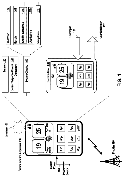
Moisture detection response
Configuration of detection of physical conditions in and/or around a communication apparatus is described.
US 9,800,810 B2 · Assignee: CANON KABUSHIKI KAISHA · Inventors: Kikuchi; Shin et al.
Sheet 1 of 22 from the published document. All sheets in the USPTO PDF
One imaging apparatus includes a first amplifier circuit, a second amplifier circuit, and a limiter circuit that limits the output of the first amplifier circuit, and further includes a configuration to clamp the output of the limiter circuit. Moreover, another imaging apparatus includes a fully differential amplifier circuit that outputs an amplified noise signal amplified from a noise signal, and an amplified optical signal amplified from an optical signal, and an output limiting circuit that limits each of the amplitude range of the amplified noise signal and the amplitude range the amplified optical signal.
Field of the Invention One disclosed aspect of the embodiments relates to an imaging apparatus and an imaging system. Description of the Related Art An imaging apparatus typically includes a photoelectric conversion portion, region, or circuit, that generates electric charge by photoelectrically converting incident light, and a floating diffusion portion, region, or circuit, that accumulates the electric charge, in which a pixel outputs an optical signal based on the potential of the floating diffusion portion. Furthermore, a configuration including an amplification portion, region, or circuit, that amplifies the optical signal output by the pixel is known as an example of the imaging apparatus. In an imaging apparatus described in Japanese Patent Laid-Open No. 2012-257029, a multi-stage amplification portion amplifies an optical signal output by a pixel. Specifically, the first stage of
1 of 22 drawing sheets so far from the published document, cropped to the drawing. Every sheet is in the USPTO PDF.
What the patent claimed, word for word. All of it is now free to use.
Field of the Invention
One disclosed aspect of the embodiments relates to an imaging apparatus and an imaging system.
Description of the Related Art
An imaging apparatus typically includes a photoelectric conversion portion, region, or circuit, that generates electric charge by photoelectrically converting incident light, and a floating diffusion portion, region, or circuit, that accumulates the electric charge, in which a pixel outputs an optical signal based on the potential of the floating diffusion portion. Furthermore, a configuration including an amplification portion, region, or circuit, that amplifies the optical signal output by the pixel is known as an example of the imaging apparatus.
In an imaging apparatus described in Japanese Patent Laid-Open No. 2012-257029, a multi-stage amplification portion amplifies an optical signal output by a pixel. Specifically, the first stage of the amplification portion amplifies an optical signal output by a pixel, and the second stage of the amplifier amplifies the signal amplified by the first stage of the amplification portion.
Moreover, in the imaging apparatus, the blackening phenomenon in which a portion having a large amount of light, which should be originally expressed as white that is highly bright, is reduced in brightness or blackens may happen when a subject having a large amount of light is photographed.
Japanese Patent Laid-Open No. 2014-212423 describes a configuration, including a limiter circuit that limits the output of an amplification portion that amplifies an optical signal output by a pixel, to reduce the blackening phenomenon.
Moreover, Japanese Patent Laid-Open No. 2007-201550 describes a configuration including a first amplifier circuit and a second amplifier circuit connected to an output node of the first amplifier circuit, the configuration including a limiter that limits the output of the first amplifier circuit and a limiter that limits the output of the second amplifier circuit.
Moreover, an imaging apparatus is known which includes an effective pixel that outputs a signal based on electric charge generated by photoelectric conversion, and a reference pixel that outputs a reference signal without performing photoelectric conversion.
As such an imaging apparatus, there is an imaging apparatus described in Japanese Patent Laid-Open No. 2012-253740. Japanese Patent Laid-Open No. 2012-253740 describes the imaging apparatus in which a fully differential amplifier circuit outputs a signal amplified from a difference between a signal output by the effective pixel and a signal output by the reference pixel.
One disclosed aspect of the embodiments has been made considering the above problems, and one aspect thereof is an imaging apparatus including a pixel having an amplifier transistor configured to output a noise signal and an optical signal based on light; an amplification portion, region, or circuit, into which the noise signal and the optical signal are input from the amplifier transistor; and a limiter circuit. The amplification portion, region, or circuit, has a first and a second amplifier circuit, the first amplifier circuit outputs, to the second amplifier circuit, a first reference signal amplified from the noise signal, and a first optical signal amplified from the optical signal, and the second amplifier circuit has a capacitive element and an amplifier. The limiter circuit is connected to an output node of the first amplifier circuit to limit the amplitude of the first reference signal output by the first amplifier circuit. The capacitive element is provided on an electric path between the limiter circuit and an input node of the amplifier. The capacitive element clamps the first reference signal whose amplitude is limited by the limiter circuit.
Moreover, another aspect is an imaging apparatus including a pixel having an amplifier transistor configured to output a noise signal and an optical signal based on light; a fully differential amplifier circuit into which the optical signal is input; and an output limiting circuit. The fully differential amplifier circuit has a first and a second output node, outputs an amplified noise signal amplified from the noise signal from the first and second output nodes, and outputs an amplified optical signal amplified from the optical signal from the first and second output nodes. The output limiting circuit is configured to limit:
the amplitudes of signals output to the first and second output nodes of the fully differential amplifier circuit,
the amplitude of the amplified noise signal to a first amplitude range, and
the amplitude of the amplified optical signal to a second amplitude range wider than the first amplitude range.
Further features of the disclosure will become apparent from the following description of exemplary embodiments (with reference to the attached drawings).
FIG. 1 is a diagram illustrating an example of the configuration of an imaging apparatus.
FIG. 2 is a diagram illustrating an example of the configuration of the imaging apparatus.
FIG. 3 is a diagram illustrating an example of the configuration of an amplifier and a limiter circuit of a first amplifier circuit.
FIG. 4 is a diagram illustrating an example of the operation of the imaging apparatus.
FIG. 5 is a diagram illustrating an example of the configuration of the amplifier and the limiter circuit of the first amplifier circuit.
FIG. 6 is a diagram illustrating an example of the configuration of the imaging apparatus.
FIG. 7 is a diagram illustrating an example of the operation of the imaging apparatus.
FIG. 8 is a diagram illustrating an example of the configuration of the imaging apparatus.
FIG. 9 is a diagram illustrating an example of the operation of the imaging apparatus.
FIG. 10 is a diagram illustrating an example of the operation of the imaging apparatus.
FIG. 11 is a diagram illustrating an example of the configuration of the imaging apparatus.
FIG. 12 is a diagram illustrating an example of the configuration of an effective pixel and a reference pixel.
FIG. 13 is a diagram illustrating an example of the configuration of a column circuit.
FIG. 14 is a diagram illustrating an example of the configuration of a clipping voltage control circuit.
FIG. 15 is a diagram illustrating an example of the operation of the imaging apparatus.
FIG. 16 is a diagram illustrating an example of the configuration of a differential amplifier, an output limiting circuit, and a CMFB circuit.
FIG. 17 is a diagram illustrating an example of the configuration of the differential amplifier, the output limiting circuit, and the CMFB circuit.
FIG. 18 is a diagram illustrating an example of the configuration of the differential amplifier, the output limiting circuit, and the CMFB circuit.
FIGS. 19A, 19B, and 19C are a diagram illustrating an example of the configuration of the column circuit and diagrams illustrating examples of the configuration of the output limiting circuit.
FIG. 20 is a diagram illustrating an example of the operation of the imaging apparatus.
FIG. 21 is a diagram illustrating an example of the configuration of the column circuit.
FIG. 22 is a diagram illustrating an example of an imaging system.
Upon photographing a subject having a large amount of light, the amplitude of a noise signal output by a pixel may increase due to the leakage of electric charge from a photoelectric conversion portion, region, or circuit, into a floating diffusion portion, region, or circuit. In this case, the output of a first amplifier circuit into which the noise signal is input (let the output be a first reference signal) changes from a reset level to a level limited by a limiter circuit. In this case, a second amplifier circuit outputs a second reference signal amplified from the first reference signal that has changed to a level limited by the limiter circuit. Therefore, the second reference signal occupies a predetermined amplitude range of the range of amplitudes that can be taken by the output of the second amplifier circuit. Furthermore, the first amplifier circuit outputs, to the second amplifier circuit, a first optical signal amplified from an optical signal output by the pixel. Furthermore, the second amplifier circuit outputs a second optical signal amplified from the first optical signal. The second reference signal occupies a predetermined amplitude range of the range of amplitudes that can be taken by the output of the second amplifier circuit. Accordingly, the range of amplitudes that can be taken by the second optical signal is reduced. Consequently, the dynamic range of an image generated using the second optical signal is reduced.
A part of embodiments described below provides a technology for preventing a reduction in dynamic range caused by the second reference signal having the predetermined amplitude range.
Embodiments are described hereinafter with reference to the drawings. First Embodiment
FIG. 1 illustrates a block diagram of an imaging apparatus of one embodiment. Pixels 102 are placed in matrix form in an imaging area 101 . A plurality of pixel columns is placed to constitute the imaging area. Vertical signal lines 103 a to 103 d are placed respectively for the pixel columns. Signals of pixel rows are read out substantially simultaneously by their corresponding vertical signal lines 103 a to 103 d . In other words, it can be said that the signals are read out in parallel. Column amplification portions or circuits 104 a to 104 d are configured to be capable of amplifying signals output to the vertical signal lines 103 a to 103 d in two amplification stages. Sample-and-hold circuits 105 a to 105 d sample the signals amplified by the column amplification portions 104 a to 104 d . The signals held by the sample-and-hold circuits 105 a to 105 d are output to horizontal output lines 106 a and 106 b on a sequential or random basis in response to drive signals from an unillustrated horizontal scan circuit. All the circuits and blocks are preferably placed on the same semiconductor substrate. At least the imaging area 101 and the column amplification portions 104 a to 104 d are required to be placed on the same semiconductor substrate. Moreover, column AD conversion circuits may be placed downstream of the column amplification portions 104 a to 104 d . The column AD conversion circuits are also placed on the same semiconductor substrate. The column amplification portions 104 a to 104 d and the sample-and-hold circuits 105 a to 105 d can be called the column circuit. The column circuit is a circuit that can perform parallel processing in time on signals read out in parallel in time to a plurality of vertical signal lines.
Various configurations can be used as the configuration of the pixel. It is preferable to use, for example, what is called an APS sensor including a photoelectric conversion portion, region, or circuit and a pixel amplification portion, region, or circuit that amplifies a signal generated by the photoelectric conversion portion since the signal-to-noise ratio can be improved.
FIG. 2 is a diagram illustrating the detailed configuration of the imaging apparatus illustrated in FIG. 1 . FIG. 2 illustrates a single column of the column circuit illustrated in FIG. 1 , the single column including the column amplification portion 104 a and the sample-and-hold circuit 105 a , and its corresponding column of the pixels 102 .
Firstly, the pixel 102 is described. The pixel 102 includes a photodiode 110 , a transfer transistor 111 , a reset transistor 112 , an amplifier transistor 113 , and a select transistor 114 . The photodiode 110 receives incident light and generates electric charge by photoelectric conversion. In the embodiment, the electric charge generated by the photodiode 110 is an electron. The transfer transistor 111 , the reset transistor 112 , and the amplifier transistor 113 are connected via an FD 95 . The FD 95 is a floating diffusion portion, region, or circuit. The floating diffusion portion converts electric charge transferred by the transfer transistor 111 from the photodiode 110 into a voltage based on a capacitance value of the floating diffusion portion. The amplifier transistor 113 is connected to the vertical signal line 103 a via the select transistor 114 . A current source 99 is connected to the vertical signal line 103 a . When the select transistor 114 is turned on, the current source 99 and the amplifier transistor 113 form a source follower circuit. The amplifier transistor 113 outputs a signal based on the potential of the FD 95 being the floating diffusion portion. The reset transistor 112 resets the potential of the FD 95 when turned on. A signal that is output by the amplifier transistor 113 to the vertical signal line 103 a via the select transistor 114 based on the reset potential of the FD 95 is expressed as the reference signal. The reference signal is a noise signal. On the other hand, a signal that is output by the amplifier transistor 113 based on the potential of the FD 95 to which the electric charge generated by the photodiode 110 has been transferred is expressed as the optical signal. A signal that is output by the pixel 102 is expressed as the pixel signal. The pixel signal includes the noise signal and the optical signal.
An unillustrated vertical scan circuit inputs a signal PTX into the transfer transistor 111 . Moreover, the unillustrated vertical scan circuit inputs a signal PRES into the reset transistor 112 . Moreover, the unillustrated vertical scan circuit inputs a signal PSEL into the select transistor 114 .
Next, the column amplification portion 104 a is described. The column amplification portion 104 a includes a first amplifier circuit 140 , a second amplifier circuit 145 , and a switch 4 . The first amplifier circuit 140 includes a capacitive element 5 , a capacitive element 6 , a switch 7 , a switch 8 , a first amplifier 151 , and a limiter circuit 152 . Moreover, the second amplifier circuit 145 includes a capacitive element 13 - 1 , a capacitive element 13 - 2 , a capacitive element 14 - 1 , a capacitive element 14 - 2 , a switch 15 - 1 , a switch 15 - 2 , and a second amplifier 153 . A reference voltage Vref is input into a non-inverting input node of the first amplifier 151 , one of input nodes of the capacitive element 13 - 2 , and one of input nodes of the capacitive element 14 - 1 . The first amplifier circuit 140 is an inverting amplifier circuit. The second amplifier circuit 145 is a non-inverting amplifier circuit. The capacitive element 13 - 1 is provided on an electric path between the limiter circuit 152 and an input node of the second amplifier 153 .
Next, the sample-and-hold circuit 105 a is described. The sample-and-hold circuit 105 a includes a switch 16 , a switch 17 , a capacitive element 18 , and a capacitive element 19 . An output switch into which a control signal from the unillustrated horizontal scan circuit is input is provided downstream of each of the capacitive elements 18 and 19 . The horizontal scan circuit sequentially selects output switches of the column circuit to output signals held by the capacitive elements 18 and 19 of the column circuit from the capacitive elements 18 and 19 to the horizontal output line 106 a.
FIG. 3 is a diagram illustrating the first amplifier and the limiter circuit 152 of the first amplifier circuit 140 . The first amplifier includes an NMOS transistor MN 1 , an NMOS transistor MN 2 , a PMOS transistor MP 1 , a PMOS transistor MP 2 , and a current source 101 . A signal output from the vertical signal line 103 a is input as an input Vinp into a gate of the NMOS transistor MN 1 via the capacitive element 5 . Moreover, the voltage Vref is input as an input Vinm into a gate of the NMOS transistor MN 2 .
The limiter circuit 152 includes a PMOS transistor MP 0 . A potential VCLP is input into a gate of the PMOS transistor MP 0 . A source of the PMOS transistor MP 0 is connected to an output node of the amplifier 101 . A drain of the PMOS transistor MP 0 is connected to a ground line. While the predetermined potential VCLP is being input into the gate of the PMOS transistor MP 0 , a voltage Vgs between the gate and the source of the PMOS transistor MP 0 increases with the increasing potential of the output node of the VCLP amplifier 101 . When the voltage Vgs becomes higher than a threshold voltage Vth of the PMOS transistor MP 0 , the PMOS transistor MP 0 is put in operation. The operation of the PMOS transistor MP 0 causes the limiter circuit 152 to limit the output of the first amplifier circuit 140 .
FIG. 4 is a timing chart illustrating the operation of the circuit illustrated in FIG. 2 . PSEL, PRES, and PTX, which are illustrated in FIG. 4 , correspond to the signals illustrated in FIG. 2 , respectively. Moreover, a signal Pin illustrated in FIG. 4 is a signal that is input into the switch 4 . The signal Pin and the signal PSEL are synchronous in the embodiment. Moreover, a signal PRES 1 illustrated in FIG. 4 is a signal that is input into the switch 7 . A signal PRES 2 is a signal that is input into the switch 15 - 2 . Moreover, a signal PCT 1 is a signal that is input into the switch 8 . A signal PCT 2 N is a signal that is input into the switch 17 . A signal PCT 2 S is a signal that is input into the switch 16 . The transistor or switch into which each signal illustrated in FIG. 4 is input is turned on when a High level (hereinafter expressed as Hi level) signal is input, and is turned off when a Low level (hereinafter expressed as Lo level) signal is input.
VLine illustrated in FIG. 4 is the potential of the vertical signal line 103 a . Moreover, Vout 1 illustrated in FIG. 4 indicates the output of the first amplifier 151 . Moreover, Vout 2 illustrated in FIG. 4 indicates the output of the second amplifier 153 .
At time t 1 , the unillustrated vertical scan circuit sets the signal level of the signal PSEL to the Hi level, and the signal level of the signal PTX to the Lo level. The unillustrated vertical scan circuit changes the signal level of the signal PRES from the Hi level to the Lo level, and cancels the reset of the FD 95 . Consequently, the amplifier transistor 113 outputs the reference signal to the vertical signal line 103 a.
In the potential VLine illustrated in FIG. 4 , a solid line represents a potential of a case where the photodiode 110 receives light from a high brightness subject. On the other hand, a broken line represents a potential of a case where the photodiode 110 receives light from a low to intermediate brightness subject.
In the outputs Vout 1 and Vout 2 , broken lines represent a potential of a case where the photodiode 110 receives light from a low to intermediate brightness subject. Moreover, in the outputs Vout 1 and Vout 2 , dot-and-dash lines represent a potential of a case where the photodiode 110 receives light from a high brightness subject when the limiter circuit 152 operates. Moreover, in the outputs Vout 1 and Vout 2 , solid lines represent a potential of a case where the photodiode 110 receives light from a high brightness subject when the limiter circuit 152 does not operate.
The potential of the potential VLine of the case where the photodiode 110 receives light from a high brightness subject is described again. When the photodiode 110 receives light from the high brightness subject, electric charge generated by the photodiode 110 leaks to the FD 95 . The leakage of electric charge makes the potential of the FD 95 to decrease. Consequently, the potential of a signal output by the amplifier transistor 113 also decreases. Accordingly, the potential VLine decreases. In other words, the amplitude of the reference signal increases with the passage of time.
At time t 1 , an unillustrated control circuit sets the signal level of the signal PRES 1 to the Hi level. Hence, even if the potential VLine changes, a change does not occur in the output Vout 1 since the first amplifier circuit 140 has been reset.
At time t 2 , the unillustrated control circuit changes the signal level of the signal PRES 1 from the Hi level to the Lo level. Consequently, the reset of the first amplifier circuit 140 is canceled. Hence, the first amplifier circuit 140 outputs a signal that has been inverted and amplified from the reference signal at an amplification factor expressed in the capacitance value of the capacitive element 5 /the capacitance value of the capacitive element 6 .
The first amplifier circuit 140 of the embodiment includes the limiter circuit 152 . A case where the limiter circuit is put in non-operation is described here.
The reset of the first amplifier circuit 140 has been canceled. Accordingly, the potential of the output Vout 1 of the first amplifier circuit 140 increases with decreasing potential VLine. In other words, the amplitude of the output Vout 1 of the first amplifier circuit 140 also increases with the increasing amplitude of the reference signal. The output Vout 1 of the first amplifier circuit 140 corresponding to the amplitude of the reference signal is a first reference signal amplified from the reference signal. In the example illustrated in FIG. 4 , at time t 4 , the first reference signal reaches a potential Vsat 0 that is at a saturation level of the output of the first amplifier circuit 140 .
Next, at time t 3 , the unillustrated control circuit changes the signal level of the signal PRES 2 from the Hi level to the Lo level. Consequently, the reset of the second amplifier circuit 145 is canceled. At this point in time, the capacitive element 13 - 1 clamps the output Vout 1 of the first amplifier circuit 140 . A difference signal being a signal of a difference between the signal clamped by the capacitive element 13 - 1 and a first optical signal is input into the second amplifier circuit 145 . The amplitude of the output Vout 2 of the second amplifier circuit 145 also increases with the increasing amplitude of the output Vout 1 of the first amplifier circuit 140 . The output Vout 2 of the second amplifier circuit 145 is a second reference signal amplified from the output Vout 1 of the first amplifier circuit 140 being the first reference signal. In response to at time t 4 , the first reference signal reaching the potential Vsat 0 that is at the saturation level, the potential of the second reference signal reaches a potential Vsat 1 that is at the saturation level of the output of the second amplifier circuit 145 .
Next, at time t 4 , the unillustrated control circuit changes the signal level of the signal PCT 2 N from the Lo level to the Hi level. The unillustrated control circuit then changes the signal level of the signal PCT 2 N from the Hi level to the Lo level at time t 5 . Consequently, the capacitive element 19 holds the potential of the output Vout 2 . Consequently, the capacitive element 19 holds the second reference signal being the signal output by the second amplifier circuit 145 .
At time t 6 , the unillustrated vertical scan circuit changes the signal level of the signal PTX from the Lo level to the Hi level. Consequently, the electric charge generated by the photodiode 110 starts being transferred to the FD 95 . At time t 7 , the unillustrated vertical scan circuit changes the signal level of the signal PTX from the Hi level to the Lo level. Consequently, the transfer of the electric charge generated by the photodiode 110 to the FD 95 ends. Consequently, the potential of the FD 95 becomes a potential based on the electric charge generated by the photodiode 110 by photoelectrically converting incident light. The amplifier transistor 113 outputs a signal based on the potential of the FD 95 to the vertical signal line 103 a via the select transistor 114 . The signal output by the amplifier transistor 113 is the optical signal.
After receiving the optical signal output by the amplifier transistor 113 , the first amplifier circuit 140 outputs, to the second amplifier circuit, a signal amplified from the optical signal. The signal amplified from the optical signal and output by the first amplifier circuit 140 is the first optical signal. In terms of the first optical signal, the signal level of the first reference signal has already reached the potential Vsat 0 that is at the saturation level, and accordingly the signal level of the first optical signal is also the potential Vsat 0 that is at the saturation level.
The second amplifier circuit 145 outputs a signal amplified from the first optical signal amplified by the first amplifier circuit 140 . The signal output by the second amplifier circuit 145 is a second optical signal amplified from the first optical signal. In terms of the second optical signal, the signal level of the second reference signal has reached the potential Vsat 1 that is at the saturation level of the second amplifier circuit 145 , and accordingly the signal level of the second optical signal is also the potential Vsat 1 that is at the saturation level.
At time t 8 , the unillustrated control circuit changes the signal level of the signal PCT 2 S from the Lo level to the Hi level. Consequently, the capacitive element 18 samples the second optical signal.
At time t 9 , the unillustrated control circuit changes the signal level of the signal PCT 2 S from the Hi level to the Lo level. Consequently, the capacitive element 18 holds the second optical signal.
At time t 10 , the unillustrated vertical scan circuit changes the signal level of the signal PSEL from the Hi level to the Lo level. The unillustrated control circuit then changes the signal level of the signal PSEL that is output to the pixel 102 in another row from the Lo level to the Hi level. The above operations are subsequently repeated. Accordingly, the reference signals and optical signals output by the pixels 102 in each row are read out.
As described above, when the limiter circuit 152 included in the first amplifier circuit 140 is put in non-operation, the amplitude of the first reference signal increases in accordance with the leakage of electric charge from the photodiode 110 to the FD 95 . Therefore, when a CDS process is performed which obtains a difference between the second reference signal held by the capacitive element 19 and the second optical signal held by the capacitive element 18 , the amplitude of the second optical signal after the CDS process becomes smaller than the original amplitude corresponding to the amount of incident light. In the example illustrated in FIG. 4 , both of the second reference signal and the second optical signal are at the signal level of the potential Vsat 1 . Hence, Vsig obtained by subtracting the second reference signal from the second optical signal is: Vsig=Vsat 1 −Vsat 1=0
Therefore, the blackening phenomenon occurs in which a portion that should be originally shown as white as an image appears black and sunk.
Next, a case where the limiter circuit 152 is operated is described. The unillustrated control circuit sets the signal level of a signal PCLP_EN to the Hi level prior to time t 1 . Consequently, the limiter circuit 152 that receives the signal PCLP_EN is in an operable state.
When the reset of the first amplifier circuit 140 is canceled at time t 2 , the amplitude of the first reference signal increases with the increasing amplitude of the reference signal. However, when the potential Vref has changed to a potential V 4 , the limiter circuit 152 limits the output of the first amplifier circuit 140 . Consequently, even if the amplitude of the reference signal increases, the signal level of the first reference signal is limited unchanged at the potential V 4 until the signal level of the signal PCLP_EN changes from the Hi level to the Lo level at time t 6 .
The second amplifier circuit 145 is reset until the signal level of the signal PRES 2 changes from the Hi level to the Lo level at time t 3 . Also at a time when the signal level of the first reference signal changes from the potential Vref to the potential V 4 , the second amplifier circuit 145 is still reset. Therefore, even if the signal level of the first reference signal changes from the potential Vref to the potential V 4 , the signal level of the second reference signal does not change.
At time t 3 , the unillustrated control circuit changes the signal level of the signal PRES 2 from the Hi level to the Lo level. Consequently, the reset of the second amplifier circuit 145 is canceled. Moreover, the capacitive element 13 - 1 clamps the output of the limiter circuit 152 . A difference signal being a signal of a difference between an output signal of the limiter circuit 152 clamped by the capacitive element 13 - 1 and the first optical signal is input into the second amplifier circuit 145 . The second amplifier circuit 145 amplifies the difference signal to generate the second optical signal.
Moreover, the signal level of the first reference signal is limited unchanged at the potential V 4 until time t 6 . Therefore, the signal level of the second reference signal also remains at the potential Vref until time t 6 .
At time t 5 , the signal level of the signal PCT 2 N changes from the Hi level to the Lo level. Consequently, the capacitive element 19 holds the second reference signal that is at the signal level of the potential Vref.
At time t 6 , the unillustrated control circuit changes the signal level of the signal PCLP_EN from the Hi level to the Lo level. Consequently, the limit of the output of the first amplifier circuit 140 by the limiter circuit 152 is canceled. Moreover, at time t 6 , the unillustrated vertical scan circuit changes the signal level of the signal PTX from the Lo level to the Hi level. The unillustrated vertical scan circuit then changes the signal level of the signal PTX from the Hi level to the Lo level at time t 7 . The limiter circuit 152 is not in operation. Accordingly, the first amplifier circuit 140 can output the first optical signal to the second amplifier circuit 145 . Operations at and after time t 8 are the same as the above-mentioned operations.
The capacitive element 18 holds the second optical signal. Moreover, the capacitive element 19 holds the second reference signal at the potential Vref. Therefore, when the limiter circuit 152 is operated, the capacitive element 19 holds the second reference signal at the potential Vref. Hence, Vsig obtained by subtracting the second reference signal from the second optical signal is: Vsig=Vsat 1 −Vref
Hence, even if the second reference signal is subtracted from the second optical signal, the blackening phenomenon does not occur.
Hence, it is possible to prevent the blackening phenomenon from occurring by the first amplifier circuit 140 including the limiter circuit 152 .
It was found that the following problem arises if the first amplifier circuit 140 is not provided with the limiter circuit and the second amplifier circuit 145 is provided with the limiter circuit.
Assume that the photodiode 110 receives light from a high brightness subject as indicated by the solid line in FIG. 4 when the first amplifier circuit 140 is not provided with the limiter circuit. In this case, the output of the first amplifier circuit 140 is not limited. Hence, the first reference signal reaches the potential Vsat 0 that is at the saturation level of the first amplifier circuit 140 . However, the output of the second amplifier circuit 145 is limited by the limiter circuit provided to the second amplifier circuit 145 . Hence, the signal level of the second reference signal does not reach the potential Vsat 1 , and is limited to an output level by the limiter circuit. The limit of the output is set to a potential V 5 (not illustrated) that is larger in amplitude than the potential Vref. The potential V 5 is expressed as: V 5 =Vref+X
The optical signal is then output to the first amplifier circuit 140 . The signal level of the first reference signal has already reached the saturation level. Accordingly, the signal level of the first optical signal is the potential Vsat 0 that is at the saturation level. On the other hand, the limiter circuit of the second amplifier circuit 145 has canceled the limit of the output of the second amplifier circuit 145 . Hence, the signal level of the second optical signal reaches the potential Vsat 1 that is at the saturation level of the second amplifier circuit 145 . Therefore, Vsig being a difference between the second optical signal and the second reference signal is: Vsig=Vsat 1 −V 5
When equation
is introduced into equation (4), it is expressed as: Vsig=Vsat 1 −Vref−X
As described above, the imaging apparatus of the embodiment includes the limiter circuit 152 that limits the amplitude of each of the first optical signal and the first reference signal. Accordingly, the blackening phenomenon can be suitably prevented.
In the imaging apparatus of the embodiment, the capacitive element 13 - 1 clamps the output of the first amplifier circuit 140 (the output of the limiter circuit 152 ) after the first reference signal reaches the second potential V 4 limited by the limiter circuit 152 . If the capacitive element 13 - 1 performs clamping before the first reference signal reaches the second potential V 4 , the amplitude of the second reference signal increases from the potential Vref. Therefore, the range that can be taken by Vsig obtained by subtracting the second reference signal from the second optical signal is reduced by the amount of change in the amplitude of the second reference signal from the potential Vref. On the other hand, in the embodiment, the capacitive element 13 - 1 performs clamping after reaching the second potential V 4 limited by the limiter circuit 152 . Accordingly, the second reference signal can remain at the potential Vref. Consequently, it is possible to prevent the reduction in the range that can be taken by Vsig obtained by subtracting the second reference signal from the second optical signal. In other words, the dynamic range of an image generated with Vsig can be prevented from reducing.
In the embodiment, one column circuit portion is provided to one column of the pixels 102 . As another example, one column circuit portion may be provided to a plurality of columns of the pixels 102 . Moreover, a plurality of column circuit portions may be provided to one column of the pixels 102 . Such arrangements fall under the category of an example where each of a plurality of column circuit portions is provided to a column in which pixels are placed.
The first amplifier circuit 140 includes the limiter circuit 152 . However, the arrangement is not limited to this example. In other words, the imaging apparatus is simply required to include the limiter circuit 152 that limits the output of the first amplifier circuit 140 . For example, it may be a mode in which a plurality of column circuits shares one limiter circuit 152 .
Moreover, the embodiment illustrates the example where the sample-and-hold circuit 105 holds the second optical signal being an analog signal and the second reference signal being an analog signal. However, the embodiment is not limited to this example. An AD conversion circuit that converts the output of the second amplifier circuit 145 into a digital signal may be further included. The AD conversion circuit converts the second optical signal and the second reference signal into digital signals respectively. The sample-and-hold circuit 105 may be configured to hold the second optical signal and the second reference signal that have been converted into digital signals.
The embodiment describes the example where the outputs of both the first amplifier circuit 140 and the second amplifier circuit 145 reach saturation when the limiter circuit 152 is not in operation. The embodiment is not limited to this example. Depending on the amplification factor set for each of the first amplifier circuit 140 and the second amplifier circuit 145 , an example is also practicable in which the first reference signal of the first amplifier circuit 140 has not reached the saturation level, but the second reference signal of the second amplifier circuit 145 reaches saturation. Also in such a case, the first reference signal and first optical signal of the first amplifier circuit 140 are limited by the limiter circuit 152 . Accordingly, the blackening phenomenon can be prevented from occurring. Moreover, the limiter circuit 152 limits the signal level of the first reference signal of the first amplifier circuit 140 even if the second amplifier circuit 145 does not reach the saturation level. Accordingly, the effect of the embodiment is achieved.
The embodiment illustrates the example where the first amplifier of the first amplifier circuit 140 is a differential amplifier. The embodiment is not limited to this example. For example, as illustrated in FIG. 5 , the first amplifier may be a common-source amplifier circuit.
The embodiment describes the example where the first amplifier circuit 140 includes the limiter circuit 152 . Furthermore, the second amplifier circuit 145 may be provided with a second limiter circuit as the limiter circuit. This case can also deal with the following mode. At a time when the reset of the second amplifier circuit 145 is canceled, the potential of the first reference signal is assumed to be a potential Vx that is smaller in amplitude than the potential limited by the limiter circuit 152 . The first reference signal reaches the potential V 4 limited by the limiter circuit 152 during a period of time between after the reset of the second amplifier circuit 145 is canceled and before time t 5 when the signal level of the signal PCT 2 N changes from the Hi level to the Lo level. The change in potential from the potential Vx to the potential V 4 may cause the second reference signal to reach the potential Vsat 1 that is at the saturation level, depending on the amplification factor of the second amplifier circuit 145 . In such a case, the second reference signal can be limited to a potential having a smaller amplitude than the potential Vsat 1 by the second amplifier circuit 145 including the second limiter circuit. Consequently, the occurrence of the blackening phenomenon can be further prevented.
The capacitance value of the capacitive element 13 - 1 and the capacitance value of the capacitive element 14 - 2 may be made the same to set the amplification factor of the second amplifier circuit 145 to one. Second Embodiment
An imaging apparatus of the embodiment is described focusing on points different from those of the first embodiment.
In terms of the column amplification portion 104 of the imaging apparatus of the first embodiment, the first amplifier circuit 140 is an inverting amplifier circuit, and the second amplifier circuit 145 is a non-inverting amplifier circuit. In terms of the column amplification portions of the imaging apparatus of the embodiment, both of the first and second amplifier circuits are inverting amplifier circuits.
The configuration of the imaging apparatus of the embodiment is the same as the configuration illustrated in FIG. 1 .
FIG. 6 is a diagram illustrating the pixel 102 , the column amplification portion 104 a , and the sample-and-hold circuit 105 a of the embodiment. The reference numerals assigned in FIG. 2 are also assigned in FIG. 6 to members of FIG. 6 having the same functions as those illustrated in FIG. 2 . The column amplification portion 104 a of the embodiment includes the first amplifier circuit 140 and a second amplifier circuit 160 . Both of the first amplifier circuit 140 and the second amplifier circuit 160 are inverting amplifier circuits.
The description continues in the full USPTO document.
About 6,824 words. The USPTO PDF has it with every drawing.
Fees are due 3.5, 7.5 and 11.5 years after grant. This patent expired on October 24, 2025, so the fee marked "not paid" was the one that went unpaid.
IMAGING APPARATUS AND IMAGING SYSTEM
Filed Aug 2016 · published Feb 2017Imaging apparatus and imaging system
Filed Aug 2016 · granted Oct 2017Earlier publications, parents and continuations. None of them can still be enforced, or this patent would not be listed.
Prior art cited by the examiner or applicant. Useful when you check your own idea for novelty.
Everything on this page comes from the documents linked above.


