 Lapsed, fee not paid34 drawings
Robotics & Automation · US 9,797,484 B2
Methods for robotic arms with strap drive trains
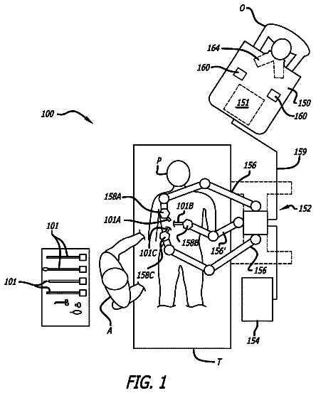
In one embodiment of the invention, a robotic arm is provided including a linkage assembly and a strap drive train.
US 9,798,312 B2 · Assignee: Mitsubishi Electric Corporation · Inventors: Iuchi; Yukihiro et al.
Sheet 1 of 16 from the published document. All sheets in the USPTO PDF
A numerical control device ( 1 ) of a machine tool capable of controlling its spindle rotating speed includes: a program analyzing unit ( 2 ) that reads ahead a machining program ( 6 ) by one block or more and analyzes a command for the machine tool; and a command determining unit ( 3 ) that determines, based on a result analyzed by the program analyzing unit ( 2 ), whether a command posterior to a spindle control command causes any machining problem when the command is executed during a spindle rotating speed change, outputs a first command, in which some problem occurs in the machining, after the spindle rotating speed reaches the commanded rotating speed, and output a second command, which is other than the first command, before the spindle rotating speed reaches the commanded rotating speed.
In a machine tool equipped with a numerical control device, machining is performed by commanding spindle rotating speed from a machining program. In the machine tool, machining cannot be performed during the period from the commanding of the spindle rotating speed until actual spindle rotating speed reaches the commanded rotating speed. Therefore, a waiting time occurs and a machining time becomes long. However, with such a numerical control device, it is unnecessary for every command to wait for the spindle rotating speed to reach commanded rotating speeds. For example, in the case of a cutting command, it is necessary to wait for the spindle rotating speed to reach a commanded rotating speed. However, in the case of the non-cutting command such as a positioning command, it is unnecessary to wait for the spindle rotating speed to reach rotating speed commanded. The determination for eac
8 of 16 drawing sheets so far from the published document, cropped to the drawing. Every sheet is in the USPTO PDF.
What the patent claimed, word for word. All of it is now free to use.
This application is a National Stage of International Application No. PCT/JP2012/062431 filed May 15, 2012, the contents of all of which are incorporated herein by reference in their entirety.
The present invention relates to a numerical control device that performs numerical control (NC) of a machine tool capable of controlling its spindle rotating speed.
In a machine tool equipped with a numerical control device, machining is performed by commanding spindle rotating speed from a machining program. In the machine tool, machining cannot be performed during the period from the commanding of the spindle rotating speed until actual spindle rotating speed reaches the commanded rotating speed. Therefore, a waiting time occurs and a machining time becomes long. However, with such a numerical control device, it is unnecessary for every command to wait for the spindle rotating speed to reach commanded rotating speeds. For example, in the case of a cutting command, it is necessary to wait for the spindle rotating speed to reach a commanded rotating speed. However, in the case of the non-cutting command such as a positioning command, it is unnecessary to wait for the spindle rotating speed to reach rotating speed commanded. The determination for each command as to whether to wait or not can be done by making a ladder. However, because the ladder is complicated, it is not easy for an operator to modify the ladder.
For example, Patent Literature 1 discloses a technology that uses a machining program in a control device to command and select whether the next block is executed after waiting for spindle rotating speed to reach commanded rotating speed or whether the next block is executed even if the spindle rotating speed has not reached the commanded rotating speed.
Patent Literature 2 discloses a technology used in a numerical control device to control the timing of the output of a spindle rotating command such that the spindle rotating speed reaches commanded rotating speed according to a timing when a cutting command is started. CITATION LIST Patent Literature
Patent Literature 1: Japanese Utility Model Publication No.
S62-179605
Patent Literature 2: Japanese Patent Application Laid-Open No. 2011-118952 SUMMARY Technical Problem
However, in the technology described in Patent Literature 1, there is a problem in that, when the control device commands to execute the next block after waiting for the spindle rotating speed to reach the commanded rotating speed, a machining time increases because the next block is executed after waiting for the spindle rotating speed to reach the commanded rotating speed even in a case of a non-cutting command such as a positioning command. In other case, there is a problem in that, when the control device commands the machine tool to execute the next block even if the spindle rotating speed does not reach the commanded rotating speed, the next block is executed even if the spindle rotating speed does not reach the commanded rotating speed even in a case of a cutting command, resulting in the deterioration of the machining accuracy.
In the technology described in Patent Literature 2, the control in the numerical control device is performed for the purpose of preventing a spindle from wastefully rotating to save power consumption. Therefore, there is a problem in that output timing of the spindle rotating command is output only later than the timing commanded by the machining program so that a machining time cannot be reduced.
The present invention has been made in view of the above and it is an object of the present invention to obtain a numerical control device capable of reducing a machining time in a machine tool without deteriorating machining accuracy. Solution to Problem
To solve the problem and achieve the object mentioned above, the present invention relates to a numerical control device of a machine tool capable of controlling its spindle rotating speed. The numerical control device includes: a program analyzing unit that reads ahead a machining program by one block or more and analyzes a command for the machine tool; and a command determining unit that determines, based on a result analyzed by the program analyzing unit, whether a command posterior to a spindle control command causes any machining problem when the command is executed during a spindle rotating speed change, outputs a first command, in which some problem occurs in the machining, after the spindle rotating speed reaches commanded rotating speed, and outputs a second command, which is other than the first command, before the spindle rotating speed reaches the commanded rotating speed. Advantageous Effects of Invention
The numerical control device according to the present invention attains an effect such that it is possible to reduce a machining time in a machine tool without deteriorating machining accuracy.
FIG. 1 is a diagram illustrating a configuration example of a numerical control device.
FIG. 2 is a flowchart illustrating a processing procedure executed by a program analyzing unit of the numerical control device according to a first embodiment.
FIG. 3 is a flowchart illustrating a processing procedure executed by a command determining unit of the numerical control device according to the first embodiment.
FIG. 4 is a diagram illustrating a machining program example processed by the numerical control device in the first embodiment.
FIG. 5 is a time chart for the machining program example shown in FIG. 4 .
FIG. 6 is a flowchart illustrating a processing procedure executed by a program analyzing unit of a numerical control device according to a second embodiment.
FIG. 7 is a flowchart illustrating a processing procedure executed by a command determining unit of the numerical control device according to the second embodiment.
FIG. 8 is a diagram illustrating a machining program example processed by the numerical control device in the second embodiment.
FIG. 9 is a time chart for the machining program example shown in FIG. 8 .
FIG. 10 is a flowchart illustrating a processing procedure executed by a program analyzing unit of a numerical control device according to a third embodiment.
FIG. 11 is a time chart for the machining program example shown in FIG. 4 .
FIG. 12 is a flowchart illustrating a processing procedure executed by a program analyzing unit in a numerical control device according to a fourth embodiment.
FIG. 13 is a flowchart illustrating a processing procedure executed by a command determining unit of the numerical control device according to the fourth embodiment.
FIG. 14 is a diagram illustrating a machining program example processed by the numerical control device in the fourth embodiment.
FIG. 15 is a time chart for the machining program example shown in FIG. 14 .
FIG. 16 is a diagram illustrating an example of a display screen in a display unit included in the numerical control device.
Embodiments of a numerical control device according to the present invention are explained in detail below with reference to the drawings. Note that the present invention is not limited to these embodiments. First Embodiment
FIG. 1 is a diagram illustrating a configuration example of a numerical control device according to the embodiment. In FIG. 1 , reference numeral 1 denotes a numerical control device. Reference numeral 2 denotes a program analyzing unit, 3 denotes a command determining unit, 4 denotes an interpolating unit, 5 denotes a spindle-control-command output unit, 6 denotes a machining program, 7 denotes a read-ahead buffer, 8 denotes a servo amplifier, 9 denotes a spindle amplifier, 10 denotes a moving command, 11 denotes a movement amount, 12 denotes a spindle control command, 13 denotes a spindle rotating speed, and 14 denotes an actual spindle rotating speed.
The program analyzing unit 2 reads and analyzes the machining program 6 and sequentially stores analysis results of read commands. In the read-ahead buffer 7 , stored is information such as modals of blocks, movement amounts of shafts, and spindle rotating speed, which are analysis results in the program analyzing unit 2 . The information stored in the read-ahead buffer 7 is deleted when a commanded operation is completed. The command determining unit 3 reads the information concerning the blocks stored in the read-ahead buffer 7 ahead and outputs commands to processing units corresponding to the commands. The moving command 10 is output to the interpolating unit 4 . The interpolating unit 4 calculates the movement amount 11 at every interpolation cycle and outputs the movement amount 11 to the servo amplifier 8 . The moving command 10 is a command for controlling the operations of a shaft such as a cutting command and a positioning command. The commands are collectively referred to as moving command 10 . The spindle control command 12 is output to the spindle-control-command output unit 5 . The spindle-control-command output unit 5 outputs the spindle rotating speed 13 to the spindle amplifier 9 . The spindle control command 12 is a command for controlling the operations of a spindle such as a spindle rotating command and a spindle stopping command. The commands are collectively referred to as spindle control command 12 . The spindle amplifier 9 outputs the actual spindle rotating speed 14 to the command determining unit 3 . The command determining unit 3 uses the actual spindle rotating speed 14 for determining the output of a command.
FIG. 2 is a flowchart illustrating a processing procedure executed by the program analyzing unit 2 of the numerical control device 1 according to the embodiment. At step S 101 , the program analyzing unit 2 determines whether a command is stored in the read-ahead buffer 7 . If a command is stored in the read-ahead buffer 7 (Yes at step S 101 ), the program analyzing unit 2 ends the processing. If a command is not stored in the read-ahead buffer 7 (No at step S 101 ), the program analyzing unit 2 proceeds to step S 102 . At step S 102 , the program analyzing unit 2 clears and sets a spindle acceleration and deceleration time T1 and time T2 from a spindle control command to 0 and proceeds to step S 103 . At step S 103 , the program analyzing unit 2 reads the machining program 6 and proceeds to step S 104 . At step S 104 , the program analyzing unit 2 determines whether the read command is the spindle control command 12 . If the read command is the spindle control command 12 (Yes at step S 104 ), the program analyzing unit 2 proceeds to step S 105 . If the read command is not the spindle control command 12 (No at step S 104 ), the program analyzing unit 2 ends the processing. At step S 105 , the program analyzing unit 2 calculates the spindle acceleration and deceleration time T1 on the basis of a method for calculating the execution time of blocks explained below and proceeds to step S 106 . At step S 106 , the program analyzing unit 2 determines whether the next block is present. If the next block is present (Yes at step S 106 ), the program analyzing unit 2 proceeds to step S 107 . If the next block is not present (No at step S 106 ), the program analyzing unit 2 ends the processing. At step S 107 , the program analyzing unit 2 reads the next block and proceeds to step S 108 . At step S 108 , the program analyzing unit 2 determines whether the read command is a command for which a problem occurs when spindle rotating speed changes. If the read command is a command for which a problem does not occur (No at step S 108 ), the program analyzing unit 2 proceeds to step S 109 . If the read command is a command for which a problem occurs (Yes at step S 108 ), the program analyzing unit 2 ends the processing. At step S 109 , the program analyzing unit 2 calculates an execution time of the read command on the basis of a method for calculating the execution times of blocks explained below and proceeds to step S 110 . At step S 110 , the program analyzing unit 2 accumulates execution times calculated at step S 109 in order to calculate the time T2 from the spindle control command and proceeds to step S 111 . At step S 111 , the program analyzing unit 2 compares the spindle acceleration and deceleration time T1 with the time T2 from the spindle control command. If the program analyzing unit 2 determines that the spindle acceleration and deceleration time T1 is larger (No at step S 111 ), the program analyzing unit 2 returns to step S 106 . If the program analyzing unit 2 determines that the time T2 from the spindle control command is larger (Yes at step S 111 ), the program analyzing unit 2 ends the processing. Note that information concerning the blocks read by the program analyzing unit 2 is sequentially stored in the read-ahead buffer 7 .
Here, a method is explained of determining a command for which a problem occurs when the spindle rotating speed changes. Examples of a command for which a problem occurs when the spindle rotating speed changes include a tool replacing command and a cutting command. The tool replacing command is usually performed in a situation in which the spindle is stopped so that the spindle cannot be rotated. The cutting command is performed in a state in which work is being machined so that accuracy of the machining deteriorates when the spindle rotating speed changes. That is, as a command posterior to the spindle rotating command, the command for which a problem occurs when the spindle rotating speed changes is the cutting command. As a command prior to the spindle rotating command, the command for which a problem occurs when the spindle rotating speed changes is the cutting command and the tool replacing command. As a command posterior to the spindle stopping command, the command for which a problem occurs when the spindle rotating speed changes is the tool replacing command. As a command prior to the spindle stopping command, the command for which a problem occurs when the spindle rotating speed changes is the cutting command. Here, a command other than the tool replacing command and the cutting command for which a problem occurs when the spindle rotating speed changes is determined by setting the command in parameters or the like in advance. The command for which a problem occurs when the spindle rotating speed changes, i.e., a command in which some problem (e.g., an increase in a machining time or deterioration in machining accuracy) occurs in machining because of implementation during the spindle rotating speed change is here referred to as a first command. A command for which a problem does not occur even if the spindle rotating speed changes, i.e., a command other than the first command in which some problem occurs in machining is referred to as a second command.
A method for calculating the execution times of blocks in the program analyzing unit 2 is explained here. In the case of the positioning command, an execution time is calculated from quick feed speed and an acceleration and deceleration time constant set in parameters in advance and a moving distance commanded by the machining program 6 (execution time=moving distance/quick feed speed+acceleration and deceleration time constant). In the case of an M code, an execution time is set in parameters in advance. In the case of the spindle control command 12 , an execution time is calculated from the maximum rotating speed and an acceleration and deceleration time constant of the spindle set in advance, spindle rotating speed commanded by the machining program 6 , and the present spindle rotating speed (execution time=(|commanded spindle rotating speed−present spindle rotating speed|)×acceleration and deceleration time constant of the spindle/maximum rotating speed).
FIG. 3 is a flowchart illustrating a processing procedure executed by a command determining unit 3 of the numerical control device 1 according to the embodiment. The command determining unit 3 sequentially performs processing on the basis of the information concerning the commands analyzed by the program analyzing unit 2 and stored in the read-ahead buffer 7 . At step S 201 , the command determining unit 3 reads one command from the read-ahead buffer 7 and proceeds to step S 202 . At step S 202 , the command determining unit 3 determines whether the read command is the spindle control command 12 . If the read command is the spindle control command 12 (Yes at step S 202 ), the command determining unit 3 proceeds to step S 203 . If the read command is not the spindle control command 12 (No at step S 202 ), the command determining unit 3 proceeds to step S 207 . At step S 203 , the command determining unit 3 outputs the spindle control command 12 , which is the read command, and proceeds to step S 204 . At step S 204 , the command determining unit 3 deletes the spindle control command 12 , which is the read command, from the read-ahead buffer 7 and proceeds to step S 205 . At step S 205 , the command determining unit 3 determines whether the next command is stored in the read-ahead buffer 7 . If the next command is stored in the read-ahead buffer 7 (Yes at step S 205 ), the command determining unit 3 proceeds to step S 206 . If the next command is not stored in the read-ahead buffer 7 (No at step S 205 ), the command determining unit 3 ends the processing. At step S 206 , the command determining unit 3 reads the next command from the read-ahead buffer 7 and proceeds to step S 207 . At step S 207 , the command determining unit 3 determines whether the read command is a command for which a problem occurs when the spindle rotating speed changes. If the read command is the command for which a problem occurs (Yes at step S 207 ), the command determining unit 3 proceeds to step S 208 . When the read command is a command for which a problem does not occur (No at step 207 ), the command determining unit 3 proceeds to step S 209 . At step S 208 , the command determining unit 3 determines whether the actual spindle rotating speed 14 reaches the commanded rotating speed. If the actual spindle rotating speed 14 does not reach the commanded rotating speed (No at step S 208 ), the command determining unit 3 waits for the actual spindle rotating speed 14 to reach the commanded rotating speed (Yes at step S 208 ) and proceeds to step S 209 . At step S 209 , the command determining unit 3 outputs the read command and ends the processing.
Note that, if the read command is the moving command such as a cutting command or a positioning command, the command determining unit 3 outputs the read command to the interpolating unit 4 . The interpolating unit 4 calculates the movement amount 11 at every interpolation cycle and outputs the movement amount 11 to the servo amplifier 8 . On the other hand, if the read command is the spindle control command 12 such as a spindle rotating command or a spindle stopping command, the command determining unit 3 outputs the read command to the spindle-control-command output unit 5 . The spindle-control-command output unit 5 outputs the spindle rotating speed 13 to the spindle amplifier 9 . Although not shown in the figure, commands other than the moving command 10 and the spindle control commands 12 are processed by the processing units corresponding to such commands. The processing is the same as the conventional processing.
A flow of processing in the numerical control device 1 is specifically explained according to the flowcharts of FIG. 2 and FIG. 3 with reference to a machining program example. FIG. 4 is a diagram illustrating the machining program example processed by the numerical control device 1 in the embodiment. First, at step S 101 , the program analyzing unit 2 confirms that a command is not stored in the read-ahead buffer 7 (No at step S 101 ). At step S 102 , the program analyzing unit 2 clears and sets the spindle acceleration and deceleration time T1 and the time T2 from the spindle control command to 0. At step S 103 , the program analyzing unit 2 reads a block of N 101 . Because the block of N 101 is a cutting command (No at step S 104 ), the program analyzing unit 2 ends the processing. In this case, a command of N 101 is stored in the read-ahead buffer 7 .
At step S 201 , the command determining unit 3 reads the command of N 101 stored in the read-ahead buffer 7 . Because the command of N 101 is the cutting command (No at step S 202 ), the command determining unit 3 proceeds to step S 207 : Yes, step S 208 : Yes, and step S 209 , outputs the cutting command, and ends the processing.
When the operation of the cutting command of N 101 is completed, at step S 101 , the program analyzing unit 2 confirms that a command is not stored in the read-ahead buffer 7 (No at step S 101 ). At step S 102 , the program analyzing unit 2 clears and sets the spindle acceleration and deceleration time T1 and the time T2 from the spindle control command to 0. At step S 103 , the program analyzing unit 2 reads a block of N 102 . Because the block of N 102 is a positioning command (No at step S 104 ), the program analyzing unit 2 ends the processing. Then, a command of N 102 is stored in the read-ahead buffer 7 .
At step S 201 , the command determining unit 3 reads the command of N 102 stored in the read-ahead buffer 7 . Because the command of N 102 is the positioning command (No at step S 202 ), the command determining unit 3 proceeds to step S 207 : No and step S 209 , outputs the positioning command, and ends the processing.
When the operation of the positioning command of N 102 is completed, the program analyzing unit 2 confirms at step S 101 that a command is not stored in the read-ahead buffer 7 (No at step S 101 ). At step S 102 , the program analyzing unit 2 clears and sets the spindle acceleration and deceleration time T1 and the time T2 from the spindle control command to 0. At step S 103 , the program analyzing unit 2 reads a block of N 103 . Because the block of N 103 is a spindle stopping command (Yes at step S 104 ), the program analyzing unit 2 proceeds to step S 104 , calculates the spindle acceleration and deceleration time T1 that is a time period until the spindle rotating speed reaches the commanded rotating speed, and proceeds to step S 106 . At step S 106 , the program analyzing unit 2 confirms that the next block is present (Yes at step S 106 ). At step S 107 , the program analyzing unit 2 reads a block of N 104 , which is the next block. Because the block of N 104 is a positioning command to return to a tool replacement position (No at step S 108 ), the program analyzing unit 2 proceeds to step S 109 and calculates an execution time of the block of N 104 . At step S 110 , the program analyzing unit 2 updates the time T2 from the spindle control command. At step S 111 , the program analyzing unit 2 compares the spindle acceleration and deceleration time T1 with the time T2 from the spindle control command. The program analyzing unit 2 , if the spindle acceleration and deceleration time T1 is larger (No at step S 111 ), returns to step S 106 .
At step S 106 , the program analyzing unit 2 confirms that the next block is present (Yes at step S 106 ). At step S 107 , the program analyzing unit 2 reads a block of N 105 , which is the next block. The program analyzing unit 2 proceeds to step S 108 . Because the block of N 105 is a tool replacing command (Yes at step S 108 ), the program analyzing unit 2 ends the processing. Here, commands of N 103 , N 104 , and N 105 are stored in the read-ahead buffer 7 .
At step S 201 , the command determining unit 3 reads the command of N 103 stored in the read-ahead buffer 7 . Because the command of N 103 is a spindle stopping command (Yes at step S 202 ), the command determining unit 3 proceeds to step S 203 and step S 204 , outputs the spindle stopping command, and deletes the spindle stopping command from the read-ahead buffer 7 . At step S 205 , the command determining unit 3 confirms that the next command is present in the read-ahead buffer 7 (Yes at step S 205 ). At step S 206 , the command determining unit 3 reads the command of N 104 . Because the command of N 104 is a positioning command to return to a tool replacement position (No at step S 207 ), the command determining unit 3 proceeds to step S 209 , outputs the positioning command to return to a tool replacement position, and ends the processing.
When the operation of the positioning command to return to a tool replacement position of N 104 is completed, because a command is still stored in the read-ahead buffer 7 at step S 101 (Yes at step S 101 ), the program analyzing unit 2 ends the processing.
At step S 201 , the command determining unit 3 reads the command of N 105 stored in the read-ahead buffer 7 . Because the command of N 105 is a tool replacing command (No at step S 202 ), the command determining unit 3 proceeds to step S 207 : Yes, step S 208 : Yes, and step S 209 , waits for the actual spindle rotating speed 14 to reach the commanded rotating speed, that is, zero speed, outputs the tool replacing command, and ends the processing.
When the operation of the tool replacing command of N 105 is completed, the program analyzing unit 2 confirms at step S 101 that a command is not stored in the read-ahead buffer 7 (No at step S 101 ). At step S 102 , the program analyzing unit 2 clears and sets the spindle acceleration and deceleration time T1 and the time T2 from the spindle control command to 0. At step S 103 , the program analyzing unit 2 reads a block of N 106 . Because the block of N 106 is a positioning command (No at step S 104 ), the program analyzing unit 2 ends the processing. In this case, a command of N 106 is stored in the read-ahead buffer 7 .
At step S 201 , the command determining unit 3 reads the command of N 106 stored in the read-ahead buffer 7 . Because the command of N 106 is a positioning command (No at step S 202 ), the command determining unit 3 proceeds to step S 207 : No and step S 209 , outputs the positioning command, and ends the processing.
Because the next block of N 107 is also the positioning command, the program analyzing unit 2 and the command determining unit 3 perform processing that is the same as the processing for the block of N 106 .
When the operation of the positioning command of N 107 is completed, at step S 101 , the program analyzing unit 2 confirms that a command is not stored in the read-ahead buffer 7 (No at step S 101 ). At step S 102 , the program analyzing unit 2 clears and sets the spindle acceleration and deceleration time T1 and the time T2 from the spindle control command to 0. At step S 103 , the program analyzing unit 2 reads a block of N 108 . Because the block of N 108 is a spindle rotating command (Yes at step S 104 ), the program analyzing unit 2 proceeds to step S 105 , calculates the spindle acceleration and deceleration time T1, and proceeds to step S 106 . At step S 106 , the program analyzing unit 2 confirms that the next block is present (Yes at step S 106 ). At step S 107 , the program analyzing unit 2 reads a block of N 109 , which is the next block. Because the block of N 109 is a positioning command (No at step S 108 ), the program analyzing unit 2 proceeds to step S 109 and calculates an execution time of the block of N 109 . At step S 110 , the program analyzing unit 2 updates the time T2 from the spindle control command. At step S 111 , the program analyzing unit 2 compares the spindle acceleration and deceleration time T1 with the time T2 from the spindle control command. The program analyzing unit 2 determines that the spindle acceleration and deceleration time T1 is larger (No at step S 111 ) and returns to step S 106 .
At step S 106 , the program analyzing unit 2 confirms that the next block is present (Yes at step S 106 ). At step S 107 , the program analyzing unit 2 reads a block of N 110 , which is the next block. Because the block of N 110 is a positioning command (No at step S 108 ), the program analyzing unit 2 proceeds to step S 109 and calculates an execution time of the block of N 110 . At step S 110 , the program analyzing unit 2 updates the time T2 from the spindle control command. At step S 111 , the program analyzing unit 2 compares the spindle acceleration and deceleration time T1 with the time T2 from the spindle control command. If the program analyzing unit 2 determines that the time T2 from the spindle control command is larger (Yes at step S 111 ), the program analyzing unit 2 ends the processing. In this case, commands of N 108 , N 109 , and N 110 are stored in the read-ahead buffer 7 .
At step S 201 , the command determining unit 3 reads the command of N 108 stored in the read-ahead buffer 7 . Because the command of N 108 is a spindle rotating command (Yes at step S 202 ), the command determining unit 3 proceeds to step S 203 and step S 204 , outputs the spindle rotating command, and deletes the spindle rotating command from the read-ahead buffer 7 . At step S 205 , the command determining unit 3 confirms that the next command is present in the read-ahead buffer 7 (Yes at step S 205 ). At step S 206 , the command determining unit 3 reads the command of N 109 . Because the command of N 109 is a positioning command (No at step S 207 ), the command determining unit 3 proceeds to step S 209 , outputs the positioning command, and ends the processing.
When the operation of the positioning command of N 109 is completed, at step S 101 , because a command is still stored in the read-ahead buffer 7 (Yes at step S 101 ), the program analyzing unit 2 ends the processing.
At step S 201 , the command determining unit 3 reads the command of N 110 stored in the read-ahead buffer 7 . Because the command of N 110 is a positioning command (No at step S 202 ), the command determining unit 3 proceeds to step S 207 : No and step S 209 , outputs the positioning command, and ends the processing.
When the operation of the positioning command of N 110 is completed, at step S 101 , the program analyzing unit 2 confirms that a command is not stored in the read-ahead buffer 7 (No at step S 101 ). At step S 102 , the program analyzing unit 2 clears and sets the spindle acceleration and deceleration time T1 and the time T2 from the spindle control command to 0. At step S 103 , the program analyzing unit 2 reads a block of N 111 . Because the block of N 111 is a cutting command (No at step S 104 ), the program analyzing unit 2 ends the processing. In this case, a command of N 111 is stored in the read-ahead buffer 7 .
At step S 201 , the command determining unit 3 reads the command of N 111 stored in the read-ahead buffer 7 . Because the command of N 111 is a cutting command (No at step S 202 ), the command determining unit 3 proceeds to step S 207 : Yes, step S 208 : Yes, and step S 209 , waits for the actual spindle rotating speed 14 to reach the commanded rotating speed, outputs the cutting command, and ends the processing.
FIG. 5 is a time chart for the machining program example shown in FIG. 4 . FIG. 5 ( 1 ) shows a conventional operation. FIG. 5 ( 2 ) shows an operation in the embodiment. The figures respectively show relations among spindle rotating speed, a shaft movement amount, and presence or absence of a tool replacing operation at the respective steps. In the conventional operation, it is determined according to a ladder whether the spindle rotating speed has reached the commanded rotating speed and then the operation proceeds to the next block. If the spindle rotating speed reaches the commanded rotating speed and then the operation proceeds to the next block, as shown in FIG. 5 ( 1 ), the positioning commands of N 104 , N 109 , and N 110 are executed after the spindle rotating speed reaches the commanded rotating speed. In contrast, in the operation in the embodiment, as shown in FIG. 5 ( 2 ), the positioning commands of N 104 , N 109 , and N 110 are executed without depending on the ladder even if the spindle rotating speed does not reach the commanded rotating speed. The tool replacing command of N 105 and the cutting command of N 111 are executed after the spindle rotating speed reaches the commanded rotating speed. Therefore, it is possible to reduce a machining time even if a complicated ladder is not configured. The read-ahead in the program analyzing unit 2 ends in a case when a command for which a problem occurs when the spindle rotating speed changes is output or in a case when the time period from the spindle control command to the command for which a problem occurs when the spindle rotating speed changes is larger than the time period until the spindle rotating speed reaches the commanded rotating speed. Therefore, it is possible to reduce an increase in a processing load in the numerical control device 1 .
As explained above, according to the embodiment, in the case of the command for which a problem occurs when the spindle rotating speed changes, the numerical control device 1 outputs the command posterior to the spindle rotating speed reaches the commanded rotating speed; and in the case of a command other than the command for which a problem occurs when the spindle rotating speed changes, the numerical control device 1 outputs the command even if the spindle rotating speed does not reach the commanded rotating speed. Due to the operation mentioned above, it is possible to reduce a machining time without making a complicated ladder and without affecting machining accuracy and a machine.
The program analyzing unit 2 can appropriately determine the number of blocks to be read ahead and can reduce an increase in a processing load of the numerical control device. Second Embodiment
FIG. 6 is a flowchart illustrating a processing procedure executed by the program analyzing unit 2 of the numerical control device 1 according to an embodiment. The flowchart of FIG. 6 is basically the same as the flowchart of FIG. 2 explained above. Therefore, differences therebetween are chiefly explained. Step S 101 , step S 102 , and step S 103 are the same as the steps shown in FIG. 2 . At step S 301 , the program analyzing unit 2 determines whether the read command is a spindle rotating command. If the read command is the spindle rotating command (Yes at step S 301 ), the program analyzing unit 2 proceeds to step S 105 . If the read command is not the spindle rotating command (No at step S 301 ), the program analyzing unit 2 ends the processing. Step S 105 , step S 106 , and step S 107 are the same as the steps shown in FIG. 2 . At step S 302 , the program analyzing unit 2 determines whether the read command is a cutting command. If the read command is not the cutting command (No at step S 302 ), the program analyzing unit 2 proceeds to step S 109 . If the read command is the cutting command (Yes at step S 302 ), the program analyzing unit 2 ends the processing. Step S 109 and step S 110 are the same as the steps shown in FIG. 2 .
FIG. 7 is a flowchart illustrating a processing procedure executed by the command determining unit 3 of the numerical control device 1 according to the embodiment. The flowchart of FIG. 7 is basically the same as the flowchart of FIG. 3 explained above. Therefore, differences therebetween are chiefly explained. Step S 201 is the same as the step shown in FIG. 3 . At step S 401 , the command determining unit 3 determines whether the read command is the spindle rotating command. If the read command is the spindle rotating command (Yes at step S 401 ), the command determining unit 3 proceeds to step S 402 . If the read command is not the spindle rotating command (No at step S 401 ), the command determining unit 3 proceeds to step S 404 . At step S 402 , the command determining unit 3 compares the spindle acceleration and deceleration time T1 with the time T2 from the spindle control command. If the command determining unit 3 determines that the spindle acceleration and deceleration time T1 is larger (No at step S 402 ), the command determining unit 3 proceeds to step S 203 . If the command determining unit 3 determines that the time T2 from the spindle control command is larger (Yes at step S 402 ), the command determining unit 3 proceeds to step S 403 . At step S 403 , the command determining unit 3 changes an acceleration and deceleration time constant of a spindle such that the spindle acceleration and deceleration time is equal to the time T2 from the spindle control command and proceeds to step S 203 . Step S 203 , step S 204 , step S 205 , and step S 206 are the same as the steps shown in FIG. 3 . At step S 404 , the command determining unit 3 determines whether the read command is a cutting command. If the read command is the cutting command (Yes at step S 404 ), the command determining unit 3 proceeds to step S 208 . If the read command is not the cutting command (No at step S 404 ), the command determining unit 3 proceeds to step S 209 . Step S 208 and step S 209 are the same as the steps shown in FIG. 3 .
A flow of processing in the numerical control device 1 is specifically explained according to the flowcharts of FIG. 6 and FIG. 7 using a machining program example. FIG. 8 is a diagram illustrating the machining program example processed by the numerical control device 1 in the embodiment. First, at step S 101 , the program analyzing unit 2 confirms that a command is not stored in the read-ahead buffer 7 (No at step S 101 ). At step S 102 , the program analyzing unit 2 clears and sets the spindle acceleration and deceleration time T1 and the time T2 from the spindle control command to 0. At step S 103 , the program analyzing unit 2 reads a block of N 201 . Because the block of N 201 is a tool replacing command (No at step S 301 ), the program analyzing unit 2 ends the processing. In this case, a command of N 201 is stored in the read-ahead buffer 7 .
At step S 201 , the command determining unit 3 reads the command of N 201 stored in the read-ahead buffer 7 . Because the command of N 201 is the tool replacing command (No at step S 401 ), the command determining unit 3 proceeds to step S 404 : No and step S 209 , outputs the tool replacing command, and ends the processing.
When the operation of the tool replacing command of N 201 is completed, at step S 101 , the program analyzing unit 2 confirms that a command is not stored in the read-ahead buffer 7 (No at step S 101 ). At step S 102 , the program analyzing unit 2 clears and sets the spindle acceleration and deceleration time T1 and the time T2 from the spindle control command to 0. At step S 103 , the program analyzing unit 2 reads a block of N 202 . Because the block of N 202 is a positioning command (No at step S 301 ), the program analyzing unit 2 ends the processing. In this case, a command of N 202 is stored in the read-ahead buffer 7 .
At step S 201 , the command determining unit 3 reads the command of N 202 stored in the read-ahead buffer 7 . Because the command of N 202 is the positioning command (No at step S 401 ), the command determining unit 3 proceeds to step S 404 : No and step S 209 , outputs the positioning command, and ends the processing.
The next block of N 203 is also the positioning command. Therefore, the program analyzing unit 2 and the command determining unit 3 perform processing that is the same as the processing for the block of N 202 .
The description continues in the full USPTO document.
About 7,210 words. The USPTO PDF has it with every drawing.
Fees are due 3.5, 7.5 and 11.5 years after grant. This patent expired on October 24, 2025, so the fee marked "not paid" was the one that went unpaid.
NUMERICAL CONTROL DEVICE
Filed May 2012 · published May 2015Numerical control device
Filed May 2012 · granted Oct 2017Earlier publications, parents and continuations. None of them can still be enforced, or this patent would not be listed.
Prior art cited by the examiner or applicant. Useful when you check your own idea for novelty.
Everything on this page comes from the documents linked above.