 Lapsed, fee not paid3 drawings
Industrial Equipment · US 9,797,819 B2
Sensor for tension measurement
A device includes a first sensor and a second sensor.
US 9,798,278 B2 · Assignee: RICOH COMPANY, LTD. · Inventors: Nagayama; Shinji et al.
Sheet 1 of 15 from the published document. All sheets in the USPTO PDF
A recording medium heating device that can heat and dry a continuous recording medium, includes multiple heating rollers, including respective heaters, disposed on a conveying path of the recording medium; and a controller to control the heaters of the heating rollers. In a starting period during which the recording medium heating device is started, the controller sets temperatures of the heaters to starting temperatures where a temperature of a heating roller positioned closest to an exit side of the conveying path is lower than a temperature of a heating roller positioned away from the exit side of the conveying path.
1.
1 of 15 drawing sheets so far from the published document, cropped to the drawing. Every sheet is in the USPTO PDF.
What the patent claimed, word for word. All of it is now free to use.
1.
The present invention relates to a recording medium heating device, a pretreatment liquid coating/drying apparatus, and a printing system.
In printing systems, such as rotary presses, in order to evaporate the solvent of ink printed on a sheet, there is a technique in which a sheet is dried by multiple heating rollers provided on the conveying path of the sheet; see, for example, JP-H10-202839-A.
In addition, image recording of an inkjet method is becoming increasingly popular these days because of its advantage that colorization can be easily realized, in addition to its advantages of low noise and low running cost. However, when an image is formed on a recording medium which is not manufacturer-specified paper, problems related to initial image quality such as image blur, image concentration change, color tone change, image show-through, etc., occur. In addition, problems related to robustness of images such as water resistance, weather resistance, etc., occur.
In order to solve this problem, a treatment liquid that has a function to agglomerate the ink is applied immediately before the ink droplets are ejected to the sheet (recording medium), thereby improving the image quality. In a case where the pretreatment liquid is applied, it is necessary to dry the sheet before the ink is ejected. Herein, in a drying device that dries the sheet with multiple heating rollers provided on the conveying path of the sheet, there is a risk of cockling occurring, that is a wave-shaped deformation of the sheet upstream of and/or downstream of the drying device.
Accordingly, for example, in JP-2012-035566-A, in order to prevent the occurrence of cockling, after the ink lands on the recording medium in the printing operation, a drying device having a seasoning unit sprays heated moist air on the recording medium.
A possible drawback of the drying device with the seasoning unit described above is that, because multiple processes are required, the configuration of the device is complicated and large scale. In addition, although since the above-described device disposes a countermeasure for the cockling during printing, the cockling is not taken into account in starting in the above-described drying device.
In view of the above circumstances, in one aspect, the present invention proposes a heating device to suppress the occurrence of the cockling in starting.
In an embodiment which solves or reduces one or more of the above-mentioned problems, the present invention provides a recording medium heating device to heat and dry a continuous recording medium, that includes multiple heating rollers, including respective heaters, disposed on a conveying path of the recording medium; and a controller to control the heaters of the heating rollers. In a starting period during which the recording medium heating device is started, the controller sets temperatures of the heaters to starting temperatures where a temperature of a heating roller positioned closest to an exit side of the conveying path is lower than a temperature of a heating roller positioned away from the exit side of the conveying path.
Another illustrative embodiment of the present invention provides a pretreatment liquid coating/drying apparatus that includes a coating device to apply a pretreatment liquid onto a continuous recording medium; and the above-described recording medium heating device.
Yet another illustrative embodiment of the present invention provides a printing system that includes the above-described pretreatment liquid coating/drying apparatus and a printing apparatus to eject ink onto the recording medium on which the pretreatment liquid is applied and dried by the pretreatment liquid coating/drying apparatus.
Other objects and further features of embodiments will become apparent from the following detailed description when read in conjunction with the accompanying drawings, in which:
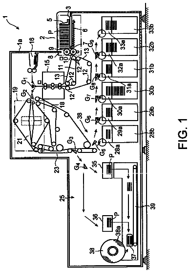
FIG. 1 is a schematic diagram illustrating a system including a recording medium heating device according to embodiments of the present invention;
FIG. 2 is a control block diagram illustrating an entire system of the heating device shown in FIG. 1 ;
FIG. 3 is a flowchart illustrating a control method shown in FIG. 1 , according to a first embodiment;
FIG. 4 is a schematic diagram of the temperatures of the first setting temperature of the heating rollers;
FIG. 5A is a graph illustrating setting temperatures of heating rollers as a comparative example;
FIG. 5B is a graph illustrating setting temperatures of the heating rollers according to the first embodiment and the second embodiment of the present invention;
FIG. 6 is a schematic diagram illustrating a printing system including the recording medium heating apparatus according to a variation of the first embodiment;
FIG. 7 is a schematic diagram illustrating a printing system according to the second embodiment of the present invention;
FIG. 8 is a schematic diagram illustrating a pretreatment liquid coating/drying apparatus used for the printing system shown in FIG. 7 ;
FIG. 9 is a control block diagram illustrating an entire printing system including the heating apparatus shown in FIG. 7 ;
FIG. 10 is a control flowchart of the printing system shown in FIG. 7 ;
FIG. 11 is a schematic diagram illustrating a pretreatment liquid coating/drying apparatus used for the printing system of a variation of the second embodiment;
FIG. 12 is a diagram illustrating the recording medium while being conveyed in the recording medium heating unit, when viewed from downstream of the conveyance direction;
FIG. 13 is a control flowchart of the printing system shown in FIG. 6 ;
FIG. 14 is a graph illustrating settings temperatures of the heating rollers according to a third embodiment and a fourth embodiment of the present invention; and
FIG. 15 is a control flowchart of the printing system shown in FIG. 11 .
In the following, embodiments of the present invention will be described with reference to the accompanying drawings. It should be noted that configuration elements which include substantially the same functional configurations in the present specification and the drawings are assigned the same reference numerals and duplicated description is omitted. Entire Configuration First Embodiment
FIG. 1 is a system (printing apparatus) 100 that employs a heating/drying device (recording medium heating device) 120 . In the system 100 according to the first embodiment shown in FIG. 1 , an image forming apparatus (recording apparatus, printer) 110 and a sheet feeding apparatus 130 are disposed upstream from the heating/drying device 120 , and a sheet after-processing apparatus 140 is disposed downstream from the heating/drying device (ink drying apparatus) 120 .
Herein, as the sheet after-processing apparatus 140 , a sheet winding apparatus to wind up the recording medium 10 after printing or a folding apparatus to fold the recording medium 10 is provided. It is to be noted that, although the heating/drying device 120 is depicted with emphasis in FIG. 1 , the actual dimension relative to the other apparatuses is different.
The image forming apparatus 110 is a printing apparatus that ejects ink onto the recording medium 10 to form images thereon, for example, a rotary press (printing machine), an inkjet printer, or a facsimile machine. The image forming apparatus 110 includes a front-side image forming unit 111 and a back-side image forming unit 112 . Head units of the image forming units 111 and 112 eject liquid such as ink onto the recording medium 10 , which forms the image on the recording medium 10 .
The recording medium 10 , output from a conveyance roller (conveyance member) 113 of the image forming apparatus 110 , is conveyed to the heating/drying device 120 via a sheet supply roller (conveyance roller) 30 , in a conveyance direction in which the recording medium 10 is conveyed as indicated by an arrow D shown in FIG. 1 . The recording medium 10 may be a given continuous sheet, alternatively; may be a relatively elongated piece of paper. The recording medium 10 may be a formed of a material, such as paper and plastic sheet, where there is a risk of suffering damage, such as wrinkling and deformation thereof by heating.
In addition, the sheet supply roller 30 is disposed on the upstream side of the heating/drying device 120 . A feed roller 71 that receives a driving rotational force from a driving force source such as motor, and a feed-nip roller 72 driven by the feed roller 71 are provided on the downstream side of the heating/drying device 120 .
The heating/drying device 120 includes a first-step heating roller set 40 , a second-step heating roller set 50 , a third-step heating roller set 60 , a sheet delivery roller 70 , and a controller 80 . The first-step heating roller set 40 includes heating rollers 40 a and 40 b , the second-step heating roller set 50 includes heating rollers 50 a and 50 b , and the third-step heating roller set 60 includes heating rollers 60 a and 60 b.
In FIG. 1 , an upper portion of the heating/drying device 120 functions as a front-side heating unit 121 , including the first-step front-side heating roller 40 b , the second-step front-side heating roller 50 b , and the third-step front-side heating roller 60 b . Moreover, a lower portion of the heating/drying device 120 functions as a back-side heating unit 122 , including the first-step back-side heating roller 40 a , the second-step back-side heating roller 50 a , the third-step back-side heating roller 60 a , and the sheet delivery roller 70 . Reference numeral 79 indicates an exit of the heating/drying device 120 , and an exit sensor 78 is provided close to the exit 79 . It is to be noted that the controller 80 including heating controllers 81 through 86 , and the exit sensor 78 are provided in either heating unit 121 or 122 .
The first-step heating roller set 40 , the second-step heating roller set 50 , and the third-step heating roller set 60 are disposed within a conveying path of the recording medium 10 in this order from upstream to downstream in the conveyance direction D.
Ends of the heating rollers 40 a , 40 b , 50 a , 50 b , 60 a , and 60 b (hereinafter referred as “ 40 a through 60 b ”) in an axial direction thereof are rotatably supported by corresponding bearings.
The first-step back-side heating roller 40 a and the first-step front-side heating roller 40 b , the second-step back-side heating roller 50 a and the second-step front-side heating roller 50 b , and the third-step back-side heating roller 60 a and the third-step front-side heating roller 60 b are separately positioned relative to each other. The heating rollers 40 a through 60 b are arranged in two rows and in a zigzag state. For example, an assumed line connecting respective rotational axes of the first-step back-side heating roller 40 a , the second-step back-side heating roller 50 a , and the third-step back-side heating roller 60 a are positioned parallel to and separated from an assumed line connecting respective rotational axes of the first-step front-side heating roller 40 b , the second-step front-side heating roller 50 b , and the third-step front-side heating roller 60 b.
Heaters 41 a , 41 b , 51 a , 51 b , 61 a , and 61 b (hereinafter referred as “ 41 a through 61 b ”), functioning as heat generators that have heat capacities to supply required heating amount for drying, are provided with the respective heating rollers 40 a through 60 b . With this configuration, the heaters 41 a through 61 b can heat the surfaces of the heating rollers 40 a through 60 b . For example, the heaters 41 a through 61 b are disposed on center positions of the heating rollers 40 a through 60 b.
Further, heat pipes (not shown) may be further provided inside of the heating rollers 40 a through 60 b , respectively. The heat pipes function as heat generating regions, covering conveyance regions on which the recording medium 10 is conveyed. Each heat pipe transfers the heat of the heating roller in an axial direction efficiently, makes the temperature of the surface of the roller uniform, and efficiently supplies (transfer) heat to the recording medium 10 .
Further, temperature sensor 42 a through 62 b (see FIG. 2 ) such as thermistors or/and thermopiles to detect the surface temperatures of the respective heating rollers 40 a through 60 b , are provided in the heating rollers 40 a through 60 b.
The respective heating rollers 40 a through 60 b are made of metal, such as aluminum. Alternately, in order to prevent the adhesion of the ink, the surface thereof may be coated with a fluoro material, and a non-adhesion film.
The heating rollers 40 a through 60 b are arranged in two rows and in the zigzag state. The recording medium 10 is wound around the respective heating rollers 40 a , 40 b , 50 a , 50 b , 60 a , and 60 b in this order from upstream side to the downstream side in the conveyance direction D. The recording medium 10 is conveyed on the respective heating rollers 40 a through 60 b in zigzag shape.
Accordingly, the back-side face of the recording medium 10 , positioned downward as shown in FIG. 1 contacts the first-step back-side heating roller 40 a , the second-step back-side heating roller 50 a , and the third-step back-side heating roller 60 a . Further, the front-side face of the recording medium 10 , positioned upward as shown in FIG. 1 contacts the first-step front-side heating roller 40 b , the second-step front-side heating roller 50 b , and the third-step front-side heating roller 60 b.
FIG. 2 shows a control block diagram illustrating an entire system including the heating/drying device 120 . As illustrated in FIG. 2 , the controller 80 of the heating/drying device 120 is installed in a control system 500 of the system (printing apparatus) 100 .
The controller 80 of the heating/drying device 120 includes heating controllers 81 through 86 , corresponding to the heating rollers 40 a through 60 b , a CPU 87 , and a memory 88 . Herein, although not shown, the controller 80 further includes a RAM and a ROM storing a program to execute heating, an I/O (input/output terminal), and an I/F (interface) to receive the data from the printing controller 90 .
The heating controllers 81 through 86 , which are connected to the heaters 41 a through 61 b configured with halogen lamps, provided inside the heating rollers 40 a through 60 b , each include heater driving circuits, etc., to adjust an applying voltage to the heaters 41 a through 61 b . While the applied voltage generated in each of the heater driving circuits is adjusted, a voltage value itself to be applied may be changed; alternatively, a predetermined voltage is applied periodically, and the voltage applying duty ratio within the duty cycle may be changed.
In addition, the heating controllers 81 through 86 , which are connected to the temperature sensors 42 a through 62 b , control the heaters 41 a through 61 b such that the surface temperatures of the heating rollers 40 a through 60 b are adjusted within a predetermined temperature range.
The memory 88 stores multiple temperature tables as combinations of first setting temperatures (temperature in starting), a second setting temperature (upper limit temperature), and third setting temperatures (homogeneously imparting amounts of heat for respective heaters (homogeneous increase in temperature)), based on types of recording medium and/or conveyance speed.
The control system 500 of the system 100 includes the printing controller 90 , an image forming controller 93 , and a conveyance controller 94 , so as to control the components of the image forming apparatus 110 .
Further, the printing controller 90 , which is connected to a control panel 91 , a personal computer (PC) or/and server 92 , the sheet feeding apparatus 130 , and the after-processing apparatus (sheet winding apparatus) 140 via multiple data lines and control lines, totally controls the image forming operation containing ink drying. The printing controller 90 executes a RIPS (Raster Image processing) process, in accordance with the printing job data supplied from, for example, a host apparatus, and generates bit map data for respective colors. In addition, the printing controller 90 generates control information to control the printing operation, based on the printing job information and the information relating to the host apparatus. Herein, the printing controller 90 may be provided inside the image forming apparatus 110 .
In the image forming apparatus 110 , the image forming controller 93 connected to the printing controller 90 controls the front-side image forming unit 111 and the back-side image forming unit 112 . Further, the conveyance controller 94 , which is connected to the conveyance roller (member) 113 in the image forming apparatus 110 and is connected to the conveyance rollers 30 and 71 disposed in vicinity of the heating/drying device 120 , controls the conveyance of the recording medium 10 .
In the controller 80 of the heating/drying device 120 , the CPU 87 controls the heating controllers 81 through 86 based on the information acquired from the connected printing controller 90 .
In the present embodiment, the controller 80 monitors the temperatures of the heating rollers 40 a through 60 b detected by the temperature sensors 42 a through 62 b , and controls the respective heaters 41 a through 61 b provided in the heating rollers 40 a through 60 b as follows. In this process, the controller 80 controls the respective heaters 41 a through 61 b provided in the heating rollers 40 a through 60 b such that the surface of the recording medium 10 on which the ink is ejected (front side, back side or both sides) is dried.
When the ink is ejected to only the front side of the recording medium 10 , the front-side heating controllers 82 , 84 , and 86 of the controller 80 control the heaters 41 b , 51 b , and 61 b , such that the heating rollers 40 b , 50 b , and 60 b are adjusted to be at the setting temperatures. Thus, the heating rollers 40 b , 50 b , and 60 b heat only the front side of the recording medium 10 to dry the ink thereon.
By contrast, when the ink is ejected to only the back side of the recording medium 10 , the back-side heating controllers 81 , 83 , and 85 of the controller 80 control the heaters 41 a , 51 a , and 61 a , such that the heating rollers 40 a , 50 a , and 60 a are adjusted to be at the setting temperatures. Thus, the heating rollers 40 a , 50 a , and 60 a heat only the back side of the recording medium 10 to dry the ink thereon.
Alternatively, when the ink is ejected to both sides of the recording medium 10 , the heating controllers 81 through 86 of the controller 80 control the heaters 41 a through 61 b , such that the respective heating rollers 40 a through 60 b are adjusted to be at the setting temperatures. Thus, the heating rollers 40 a through 60 b heat both sides of the recording medium 10 to dry the ink thereon.
The recording medium 10 is conveyed from the image forming apparatus 110 provided upstream from the heating/drying device 120 in a state in which the ink is ejected to at least one side of the recording medium 10 . The recording medium 10 conveyed into the heating/drying device 120 , initially contacts an outer circumferential surface of the first-step heating roller 40 a . The contact face of the recording medium 10 is heated to an appropriate temperature by the heating roller 40 a or 40 b , to evaporate moisture and solvent in the ink landing on the recording medium 10 . This evaporation is executed for the first step, the second step, and the third step of the heating rollers 40 a through 60 b , which can dry the ink landing on the recording medium 10 .
In this way, in a case where the ink lands on either the front side or the back side of the recording medium 10 , the only ink landing side of the recording medium 10 is dried. Herein, in a case where only one side of the recording medium 10 is dried, or in a case where the operation of the heating/drying device 120 is stopped, the controller 80 may shut off the respective heaters 41 a through 61 b . Alternatively, in the case where either front side or back side is dried, the controller 80 may operate the heaters that is not being heated such that the temperatures of the heating rollers for the face opposite to the face on which the ink lands, is set at a waiting temperature that is lower than the setting temperature of the heating rollers.
For example, the temperatures of the heating rollers 40 a through 60 b for the heating side, that is the side on which the ink lands, are 60° C. to 120° C., and the standby temperatures are, for example from 40° C. to 45° C. Herein, when the temperature exceeds 45° C., the recording medium 10 may thermally deform, and when the temperature is equal to or lower than 40° C., it is not effective for retaining warmth. Therefore, the temperature range from 40° C. to 45° C. is the suitable standby temperature range.
The controller 80 controls the temperatures of the respective heating rollers 40 a through 60 b based on the actual temperatures of the heating rollers 40 a through 60 b detected by the temperature sensors 42 a through 62 b , and based on the operation state, such as at the rotational velocities of the sheet delivery roller 70 and/or the sheet supply roller 30 .
Herein, when the ink lands on one of the front side or the back side of the recording medium 10 , the controller 80 controls the respective heaters 41 a through 61 b , such that water contents of the recording medium 10 discharged from the heating/drying device 120 are set equal to the water contents of the recording medium 10 fed by the sheet feeding apparatus 130 . That is, the controller 80 controls the respective heaters 41 a through 61 b such that the total amount W of heat supplied to the recording medium 10 from the heating rollers 40 a through 60 b for use (total amount of heat corresponding to the increased amount of setting temperature in the respective steps) exceeds the sufficient amount to evaporate the moisture and the solvent contained in the ink landing on the recording medium 10 .
Herein, assuming that all the heating rollers 40 a through 60 b are set to the temperatures that are equivalent to the maximum temperature of the setting temperature whose amounts of heat for imparting all the heating rollers are equal, when the recording medium 10 enters the heating/drying device 120 during printing, the temperature of the recording medium 10 may be rapidly raised. Thus, due to the heat load exerted by the heating roller 40 a positioned on the entrance side, there is a risk of suffering damage such as wrinkling and deformation of the recording medium 10 by heating.
In order to solve this problem, during continuous drying, the temperature of the heating roller positioned on the entrance side is set lower and that on the exit side is set higher, thereby setting temperatures having a temperature gradient, such that the amounts of heat imparted by the multiple heating rollers for the recording medium 10 are equivalent (homogeneously imparting the amounts of heat caused by temperature increase based on duty ratios in the heaters). By setting the continuous drying temperatures having the temperature gradient, the heat amount required for drying can be applied to the recording medium 10 efficiently. The temperatures of the heating rollers are controlled so as to gradually increase the temperature (heating amount) applying to the recording medium 10 from upstream side to downstream side and perform efficient drying. Further, by setting the continuous drying temperatures having the temperature gradient, any damage to the recording medium 10 is made uniform and the heat loss of the respective rollers 40 a through 60 b are made uniform so that the risk occurring the excess temperature increase is dispersed, which can normalize (make uniform) the device service lives of the respective heaters 41 a through 61 b.
As described above, considering the damage from the heating roller 40 a that initially contact during continuous drying, the example of the setting temperatures having temperature gradient is shown in TABLE 1.
TABLE-US-00001 TABLE 1 REQUIRED AMOUNT OF HEAT PRINTING CONDITION FOR HEATING ROLLERS TYPES OF AMOUNT OF FIRST-STEP SECOND-STEP THIRD-STEP PRINTING RECORDING APPLYING HEATING HEATING HEATING SPEED MEDIUM LIQUD ROLLER SET 40 ROLLER SET 50 ROLLER SET 60 *.sup.350 mpm COATED A pattern 50 65 80 PAPER A *.sup.130 mpm COATED B pattern 40 50 60 PAPER A .sup. 50 mpm COATED A pattern 60 75 90 PAPER B *.sup.230 mpm COATED B pattern 50 60 70 PAPER B .sup. 50 mpm COATED A pattern 90 105 120 PAPER C *.sup.430 mpm COATED B pattern 80 90 100 PAPER C
As illustrated in TABLE 1, the amounts of heat required for supplying the recording medium 10 from the respective heating rollers 40 a through 60 b differ depending on types (thickness, width) of recording medium 10 . Further, the required heat amount changes depending on the time during which the recording medium 10 contacts the respective heating rollers 40 a through 60 b (conveyance speed of the recording medium 10 ), at rotational velocities of the sheet discharge roller 70 and/or the sheet supply roller 30 .
Using settings based on the TABLE 1, the recording medium 10 initially will contact the first-step heating roller set 40 whose setting temperature is lowest in the heating roller sets 40 , 50 , and 60 , which can reduce the temperature difference between the recording medium 10 and the heating roller 40 a that initially contacts the recording medium 10 . Accordingly, compared with the case where all the heating rollers 40 a through 60 b are set to the highest setting temperature, the rapid temperature increase in the recording medium 10 can be avoided. Therefore, the system including the heating/drying device 120 can minimize the heat load exerted on the recording medium 10 . Thus, suffering the damage such as wrinkling and deforming of the recording medium 10 due to the heat load can be suppressed.
As described above, in order to make the heat supplying amount for the respective steps uniform during continuous printing (drying), it is preferable that the temperatures of the multiple heating rollers be set to have a predetermined temperature gradient. Herein, in order to make the amounts of heat imparted during the respective steps equal while ensuring the heat amount required for drying the sheet, it is necessary to raise the temperature of the heating rollers 60 a and 60 b provided on the downstream side (third step).
However, in a case where the temperatures are set to have the temperature gradient, even though the condition of the coated paper A, pattern B, 30 mpm of the conveyance speed, that is the lowest temperature for use shown in *1 in TABLE 1 are used, in starting printing, that is, in a starting period during which the heating/drying device 120 is starting, the temperatures of the heating rollers 60 a and 60 b are raised to 60° C. If the temperatures the third-step heating rollers 60 a , 60 b positioned on the downstream side (exit side) have been raised to the highest setting temperature in the starting period during which the heating/drying device 120 is starting, it is a risk that the area of the recording medium 10 contacting the third-step heating rollers 60 a , 60 b on the exit side may thermally shrink due to the evaporation of the moisture in the ink in a width direction of the recording medium 10 . By contrast, on the outer side (at normal temperature) on the heating/drying device 120 , due to the thermal shrinkage of the recording medium 10 caused by the heating rollers, the recording medium 10 rapidly absorbs moisture of the ink immediately after the exit of the heating/drying device 120 due to the temperature and the humidity difference between inside and outside of the heating/drying device 120 .
Accordingly, the width of the recording medium positioned outside is different from the width of the recording medium positioned inside, which generates the shrinkage difference between the area positioned outside of the heating/drying device 120 and the area contacting the heating roller 60 a or 60 b positioned inside on the exit side, caused by a temperature difference and a humidity difference. Thus, cockling (waveform deformation) may occur, in the recording medium 10 .
It is to be noted that, although the recording medium 10 may thermally shrink caused by the contact of the heating roller 40 a provided on the upstream side, considering that the setting temperature for the upstream side is lower than that for the downstream side, a lesser degree of the cockling may occur on the upstream side by continuously passing the recording medium 10 through the drying process containing the heating rollers.
In order to solve this problem, in the present invention, in order to alleviate the damage to the recording medium 10 caused by the first-step heating rollers 40 a and 40 b that initially come in contact with the recording medium 10 during continuous printing, and in order alleviate the shrinkage of the recording medium 10 caused by the third-step heating roller 60 a and 60 b provided on the exit side in the starting period of printing, setting temperatures are changed for each time period.
More specifically, in the starting period during which the heating/drying device 120 is starting, the temperatures of the heating rollers 60 a and 60 b positioned on the exit side of the conveying path are set lower than the temperatures of the heating rollers 40 a , 40 b , 50 a , and 50 b positioned far from the exit side. Specifically, in the starting period during which the heating/drying device 120 is starting, in order to apply the necessary minimum value, first setting temperatures are set such that the temperatures of the heating rollers 40 a , 60 a and 60 b positioned on the entrance side and positioned on the exit side are lower than the temperatures of the heating rollers 40 b , 50 a , and 50 b positioned on the center area.
Then, in order not to decrease below the needed heat amount, temperatures of all the heating rollers 40 a through 60 b are increased toward the upper limit temperatures (second setting temperatures). In addition, during continuous printing, the temperatures of the multiple heating rollers 40 a through 60 b are shifted to the third setting temperatures having the temperature gradient in which the amounts of heat imparted to the respective heaters 41 a through 61 b are set to be equal.
The schematic temperature control of the drying process in the heating/drying device 120 is described below. FIG. 3 is a control flowchart of the system (printing apparatus) 100 . The flow relating to heating is mainly described. Herein, FIG. 5A is a graph illustrating temperatures of the heating rollers based on the temperature gradient, as a comparative example. FIG. 5B is a graph illustrating setting temperatures of the heating roller according to one example of the embodiments (first and second embodiments) of the present invention. The example of the FIG. 5B shows the temperature transition of the setting temperature in a case where coated paper A, pattern A, conveyance speed 50 mpm, and 80° C. of the maximum value of the settings temperatures having temperature gradient are used (which corresponds to the temperatures of TABLE 3 of the second embodiment, and the temperature transition of the setting temperature is similar to this graph).
In FIG. 3 , when a print start is commanded from the control panel 91 and the PC/server 92 at step S 100 , the system 100 starts a printing preparation process (timing is shown in FIG. 5B , step S 101 ).
As the printing preparation process (S 102 ), the printing controller (host apparatus) 90 recognizes the information of the printing type, the information of the recording medium 10 , the information of the conveyance of the recording medium 10 , acquired from the control panel 91 and the PC/server 92 , so as to determine the setting temperatures. The information of the printing types means that the printing is one-side (front side only or back side only) or duplex printing. The information of the recording medium is what type the recording medium is (normal or coated paper) or how wide the recording paper is, and how long the recording medium (paper roll) is. The conveyance information means the conveyance speed (printing speed), conveyance amount (the number of copy pages).
At S 103 , the CPU 87 included in the controller 80 of the heating/drying device 120 selects the suitable (optimum) temperature tables, for example TABLE 2, that shows combinations of the suitable first, second and third step setting temperatures, from the memory 88 , in accordance with the information of the recording medium 10 acquired at step S 102 .
TABLE-US-00002 TABLE 2 REQUIRED SETTING TEMPERATURE HEATING SECOND THIRD SETTING AMOUNT SETTING TEMPERATURE HAVING FIRST SETTING TEMPERATURE HOMOGENEOUSLY TEMPERATURE TEMPERATURE UPPER LIMIT IMPARTING GRADIENT IN STARTING TEMPERATURE AMOUNT OF HEAT FIRST STEP 50 50 70 50 BACK-SIDE HEATING ROLLER 40a FIRST STEP 50 70 70 50 FRONT-SIDE HEATING ROLLER 40b SECOND STEP 60 70 70 60 BACK-SIDE HEATING ROLLER 50a SECOND STEP 60 70 70 60 FRONT-SIDE HEATING ROLLER 50b THIRD STEP 70 55 70 70 BACK-SIDE HEATING ROLLER 60a THIRD STEP 70 40 70 70 FRONT-SIDE HEATING ROLLER 60b
Herein, as for the ink drying, TABLE 2 shows the temperature transition of the setting temperatures in a case where coated paper B, pattern B, conveyance speed 30 mpm, and 70° C. of the maximum value of the setting temperatures having the temperature gradient (continuous drying temperature) are used. In the setting of TABLE 2, while the upper limit temperature (second setting temperature) is 70° C., as a combination of the first setting temperatures, the temperature of the heating roller 60 b positioned on the most downstream side (hereinafter most downstream heating roller 60 b ) is set to 40° C., and the temperature of the heating roller 60 a positioned on the second-most downstream side (hereinafter second-most downstream) is set to 55° C. Herein, even when the heating rollers 40 a through 60 b are heated according to the setting temperature table of TABLE 2, the heat amount required for the above-described drying can be entirely ensured.
As the first setting temperature in starting (starting temperatures), the temperatures are set such that, the temperature of the most downstream heating roller 60 b is 40° C., the temperature of the second-most downstream heating roller 60 a is 55° C., the temperature of the heating roller 40 a positioned on the most upstream side (most upstream heating roller 40 a ) is 50° C., and the heating rollers 40 b , 50 a , and 50 b positioned on the inside area (center area) is 70° C. that is required for drying.
FIG. 4 is a schematic diagram of the rollers and the first setting temperatures of the present embodiment. With this setting, the sheet shrinkage in the recording medium 10 caused by the temperature-humidity difference between the contact area contacting the heating roller 60 b and an area of the recording medium 10 positioned outside on the downstream of the heating/driving device 120 can be alleviated. Further, by setting such that the temperature difference between the heating rollers 50 b and 60 a and between the heating rollers 60 a and 60 b are set to 15° C., the temperature gradually changes. Changing the amount of sheet shrinkage of the recording medium 10 due to the temperature difference among the heating rollers can be alleviated, and to achieve the effect to reduce the occurrence of cockling in the recording medium entirely.
Further, by setting the most upstream heating roller 40 a to 50° C., the sheet shrinkage of the recording medium 10 caused by the temperature-humidity difference between the contact area contacting the heating roller 40 and the area positioned outside on the entrance side of the heating/driving device 120 can be alleviated. At this time, the temperature difference between the most upstream heating roller 40 a and the second-most upstream heating roller 40 b is set to 20° C., and the recording medium 10 continuously comes in contact with the heating rollers 40 b , 50 a , and 50 b inside the heating/drying device 120 . Thus, the shrinkage difference among located positions in the recording medium 10 can be alleviated, and the cockling between the most upstream heating roller 40 a and the second-most upstream heating roller 40 b cannot occur.
Herein, in the first setting temperature, the temperatures of the heating rollers 40 a through 60 b cannot be increased gradually, and the amount of heat imparted to the respective heaters (heater lamps) 41 a through 61 b cannot be made equal. However, the final temperatures (third setting temperatures) during printing is set to the temperatures whose amounts of heat imparted during the respective steps of the heaters can be made equal. Accordingly, the third setting temperature corresponding to amount of heat equally imparted to the respective steps can be independently set.
Based on a print start command from the printing controller 90 , at S 104 , in the controller 80 of the heating/drying device 120 , with reference to the temperature table, the heating controllers 81 through 86 heat the heating rollers 40 a through 60 b toward the first setting temperature (starting temperatures) (at the timing t 0 in FIG. 5B ).
Subsequently, at S 105 , the controller 80 determines whether the respective heating rollers 40 a through 60 b are heated to the first setting temperatures, based on the outputs of the respective temperature sensors 42 a through 62 b , at the timing t 1 shown in FIG. 5B . Then, when the heating rollers 40 a through 60 b have been raised to the respective first setting temperatures (Yes at S 105 ), the controller 80 reports that the printing preparation is finished to the printing controller 90 , thereby starting the printing.
At step S 106 , the printing controller 90 controls the conveyance controller 94 such that the sheet feeding apparatus 130 and the respective conveyance rollers 113 , 30 , and 71 are driven to convey the recording medium 10 . At this time, the image forming units 111 and 112 of the image forming apparatus 110 start operation, to start the printing operation to eject the ink to the recording medium 10 onto the recording medium 10 .
Along with the conveyance at S 106 , in the starting period during which the printing is started and the conveyance of the recording medium 10 is started, the temperatures of the heating rollers 40 a through 60 b are all increased toward the same second setting temperature (timing t 1 ′ shown in FIG. 5B ). Herein, in the present embodiment, the second setting temperature has the same values as the maximum value of the continuous drying setting temperatures having the temperature gradient.
The description continues in the full USPTO document.
About 6,689 words. The USPTO PDF has it with every drawing.
Fees are due 3.5, 7.5 and 11.5 years after grant. This patent expired on October 24, 2025, so the fee marked "not paid" was the one that went unpaid.
RECORDING MEDIUM HEATING DEVICE, PRETREATMENT LIQUID COATING/DRYING APPARATUS, AND PRINTING SYSTEM
Filed May 2015 · published Dec 2015Recording medium heating device, pretreatment liquid coating/drying apparatus, and printing system
Filed May 2015 · granted Oct 2017Earlier publications, parents and continuations. None of them can still be enforced, or this patent would not be listed.
Prior art cited by the examiner or applicant. Useful when you check your own idea for novelty.
Everything on this page comes from the documents linked above.