Technical field of the invention
The present invention relates, generally, to the field of remote imaging techniques and, more particularly, to a system for rendering high-resolution, high accuracy, low distortion digital images over very large fields of view.
Background of the invention
Remote sensing and imaging are broad-based technologies having a number of diverse and extremely important practical applications—such as geological mapping and analysis, and meteorological forecasting. Aerial and satellite-based photography and imaging are especially useful remote imaging techniques that have, over recent years, become heavily reliant on the collection and processing of data for digital images, including spectral, spatial, elevation, and vehicle location and orientation parameters. Spatial data—characterizing real estate improvements and locations, roads and highways, environmental hazards and conditions, utilities infrastructures (e.g., phone lines, pipelines), and geophysical features—can now be collected, processed, and communicated in a digital format to conveniently provide highly accurate mapping and surveillance data for various applications (e.g., dynamic GPS mapping). Elevation data may be used to improve the overall system's spatial and positional accuracy and may be acquired from either existing Digital Elevation Model (DEM) data sets or collected with the spectral sensor data from an active, radiation measuring Doppler based devices, or passive, stereographic calculations.
Major challenges facing remote sensing and imaging applications are spatial resolution and spectral fidelity. Photographic issues, such as spherical aberrations, astigmatism, field curvature, distortion, and chromatic aberrations are well-known problems that must be dealt with in any sensor/imaging application. Certain applications require very high image resolution—often with tolerances of inches. Depending upon the particular system used (e.g., aircraft, satellite, or space vehicle), an actual digital imaging device may be located anywhere from several feet to miles from its target, resulting in a very large scale factor. Providing images with very large scale factors, that also have resolution tolerances of inches, poses a challenge to even the most robust imaging system. Thus, conventional systems usually must make some trade-off between resolution quality and the size of a target area that can be imaged. If the system is designed to provide high-resolution digital images, then the field of view (FOV) of the imaging device is typically small. If the system provides a larger FOV, then usually the resolution of the spectral and spatial data is decreased and distortions are increased.
Ortho-imaging is an approach that has been used in an attempt to address this problem. In general, ortho-imaging renders a composite image of a target by compiling varying sub-images of the target. Typically, in aerial imaging applications, a digital imaging device that has a finite range and resolution records images of fixed subsections of a target area sequentially. Those images are then aligned according to some sequence to render a composite of a target area.
Often, such rendering processes are very time-consuming and labor intensive. In many cases, those processes require iterative processing that measurably degrades image quality and resolution—especially in cases where thousands of sub-images are being rendered. In cases where the imaging data can be processed automatically, that data is often repetitively transformed and sampled—reducing color fidelity and image sharpness with each successive manipulation. If automated correction or balancing systems are employed, such systems may be susceptible to image anomalies (e.g., unusually bright or dark objects)—leading to over or under-corrections and unreliable interpretations of image data. In cases where manual rendering of images is required or desired, time and labor costs are immense.
There is, therefore, a need for an ortho-image rendering system that provides efficient and versatile imaging for very large FOVs and associated data sets, while maintaining image quality, accuracy, positional accuracy and clarity. Additionally, automation algorithms are applied extensively in every phase of the planning, collecting, navigating, and processing all related operations.
Summary of the invention
The present invention relates to remote data collection and processing system using a variety of sensors. The system may include computer console units that control vehicle and system operations in real-time. The system may also include global positioning systems that are linked to and communicate with the computer consoles. Additionally, cameras and/or camera array assemblies can be employed for producing an image of a target viewed through an aperture. The camera array assemblies are communicatively connected to the computer consoles. The camera array assembly has a mount housing, a first imaging sensor centrally coupled to the housing having a first focal axis passing through the aperture. The camera array assembly also has a second imaging sensor coupled to the housing and offset from the first imaging sensor along an axis, that has a second focal axis passing through the aperture and intersecting the first focal axis within an intersection area. The camera array assembly has a third imaging sensor, coupled to the housing and offset from the first imaging sensor along the axis, opposite the second imaging sensor, that has a third focal axis passing through the aperture and intersecting the first focal axis within the intersection area. Any number of one-to-n cameras may be used in this manner, where “n” can be any odd or even number.
The system may also include an Attitude Measurement Unit (AMU) such as inertial, optical, or similar measurement units communicatively connected to the computer consoles and the camera array assemblies. The AMU may determine the yaw, pitch, and/or roll of the aircraft at any instant in time and successive DGPS positions may be used to measure the vehicle heading with relation to geodesic north. The AMU data is integrated with the precision DGPS data to produce a robust, real-time AMU system. The system may further include a mosaicing module housed within the computer consoles. The mosaicing module includes a first component for performing initial processing on an input image. The mosaicing module also includes a second component for determining geographical boundaries of an input image with the second component being cooperatively engaged with the first component. The mosaicing module further includes a third component for mapping an input image into the composite image with accurate geographical position. The third component being cooperatively engaged with the first and second components. A fourth component is also included in the mosaicing module for balancing color of the input images mapped into the composite image. The fourth component can be cooperatively engaged with the first, second and third components. Additionally, the mosaicing module can include a fifth component for blending borders between adjacent input images mapped into the composite image. The fifth component being cooperatively engaged with the first, second, third and fourth components.
A sixth component, an optional forward oblique and/or optional rear oblique camera array system may be implemented that collects oblique image data and merges the image data with attitude and positional measurements in order to create a digital elevation model using stereographic techniques. Creation of which may be performed in real-time onboard the vehicle or post processed later. This sixth component works cooperatively with the other components. All components may be mounted to a rigid platform for the purpose of providing co-registration of sensor data. Vibrations, turbulence, and other forces may act on the vehicle in such a way as to create errors in the alignment relationship between sensors. Utilization of common, rigid platform mount for the sensors provides a significant advantage over other systems that do not use this co-registration architecture.
Further, the present invention may employ a certain degree of lateral oversampling to improve output quality and/or co-mounted, co-registered oversampling to overcome physical pixel resolution limits.
Brief description of the drawings
For a better understanding of the invention, and to show by way of example how the same may be carried into effect, reference is now made to the detailed description of the invention along with the accompanying figures in which corresponding numerals in the different figures refer to corresponding parts and in which:
FIG. 1 illustrates a vehicle based data collection and processing system of the present invention;
FIG. 1A illustrates a portion of the vehicle based data collection and processing system of FIG. 1 ;
FIG. 1B illustrates a portion of the vehicle based data collection and processing system of FIG. 1 ;
FIG. 2 illustrates a vehicle based data collection and processing system of FIG. 1 with the camera array assembly of the present invention shown in more detail;
FIG. 3 illustrates a camera array assembly in accordance with certain aspects of the present invention;
FIG. 4 illustrates one embodiment of an imaging pattern retrieved by the camera array assembly of FIG. 1 ;
FIG. 5 depicts an imaging pattern illustrating certain aspects of the present invention;
FIG. 6 illustrates an image strip in accordance with the present invention;
FIG. 7 illustrates another embodiment of an image strip in accordance with the present invention;
FIG. 8 illustrates one embodiment of an imaging process in accordance with the present invention;
FIG. 9 illustrates diagrammatically how photos taken with the camera array assembly can be aligned to make an individual frame;
FIG. 10 is a block diagram of the processing logic according to certain embodiments of the present invention;
FIG. 11 is an illustration of lateral oversampling looking down from a vehicle according to certain embodiments of the present invention;
FIG. 12 is an illustration of lateral oversampling looking down from a vehicle according to certain embodiments of the present invention;
FIG. 13 is an illustration of flight line oversampling looking down from a vehicle according to certain embodiments of the present invention;
FIG. 14 is an illustration of flight line oversampling looking down from a vehicle according to certain embodiments of the present invention;
FIG. 15 is an illustration of progressive magnification looking down from a vehicle according to certain embodiments of the present invention;
FIG. 16 is an illustration of progressive magnification looking down from a vehicle according to certain embodiments of the present invention;
FIG. 17 is an illustration of progressive magnification looking down from a vehicle according to certain embodiments of the present invention;
FIG. 18 is a schematic of the system architecture according to certain embodiments of the present invention;
FIG. 19 is an illustration of lateral co-mounted, co-registered oversampling in a sidelap sub-pixel area for a single camera array looking down from a vehicle according to certain embodiments of the present invention;
FIG. 20 is an illustration of lateral co-mounted, co-registered oversampling in a sidelap sub-pixel area for two overlapping camera arrays looking down from a vehicle according to certain embodiments of the present invention; and
FIG. 21 is an illustration of fore and lateral co-mounted, co-registered oversampling in sidelap sub-pixel areas for two stereo camera arrays looking down from a vehicle according to certain embodiments of the present invention.
Detailed description of the invention
While the making and using of various embodiments of the present invention are discussed in detail below, it should be appreciated that the present invention provides many applicable inventive concepts, which can be embodied in a wide variety of specific contexts. The specific embodiments discussed herein are merely illustrative of specific ways to make and use the invention and do not limit the scope of the invention.
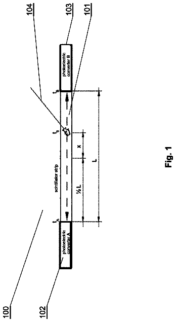
A vehicle based data collection and processing system 100 of the present invention is shown in FIGS. 1, 1A, and 1B . Additional aspects and embodiments of the present invention are shown in FIGS. 2 and 18 . System 100 includes one or more computer consoles 102 . The computer consoles contain one or more computers 104 for controlling both vehicle and system operations. Examples of the functions of the computer console are the controlling digital color sensor systems that can be associated with the data collection and processing system, providing the display data to a pilot, coordinating the satellite generated GPS pulse-per-second (PPS) event trigger (which may be 20 or more pulses per second), data logging, sensor control and adjustment, checking and alarming for error events, recording and indexing photos, storing and processing data, flight planning capability that automates the navigation of the vehicle, data, and providing a real-time display of pertinent information. A communications interface between the control computer console and the vehicle autopilot control provides the ability to actually control the flight path of the vehicle in real-time. This results in a more precise control of the vehicle's path than is possible by a human being. All of these functions can be accomplished by the use of various computer programs that are synchronized to the GPS PPS signals and take into account the various electrical latencies of the measurement devices. In an embodiment, the computer is embedded within the sensor.
One or more differential global positioning systems 106 are incorporated into the system 100 . The global positioning systems 106 are used to navigate and determine precise flight paths during vehicle and system operations. To accomplish this, the global positioning systems 106 are communicatively linked to the computer console 102 such that the information from the global positioning systems 106 can be acquired and processed without flight interruption. Zero or more GPS units may be located at known survey points in order to provide a record of each sub-seconds' GPS satellite-based errors in order to be able to back correct the accuracy of the system 100 . GPS and/or ground based positioning services may be used that eliminate the need for ground control points altogether. This technique results in greatly improved, sub-second by sub-second positional accuracy of the data capture vehicle.
One or more AMUs 108 that provide real-time yaw, pitch, and roll information that is used to accurately determine the attitude of the vehicle at the instant of data capture are also communicatively linked to the computer console 102 . The present attitude measurement unit (AMU) (e.g., Applanix POS AV), uses three high performance fiber optic gyros, one gyro each for yaw, pitch, and roll measurement. AMUs from other manufacturers, and AMUs that use other inertial measurement devices can be used as well. Additionally, an AMU may be employed to determine the instantaneous attitude of the vehicle and make the system more fault tolerant to statistical errors in AMU readings. Connected to the AMU can be one or more multi-frequency DGPS receivers 110 . The multi-frequency DGPS receivers 110 can be integrated with the AMU's yaw, pitch, and roll attitude data in order to more accurately determine the location of the remote sensor platform in three dimensional space. Additionally, the direction of geodesic North may be determined by the vector created by successive DGPS positions, recorded in a synchronized manner with the GPS PPS signals.
One or more camera array assemblies 112 for producing an image of a target viewed through an aperture are also communicatively connected to the one or more computer consoles 102 . The camera array assemblies 112 , which will be described in greater detail below, provide the data collection and processing system with the ability to capture high resolution, high precision progressive scan or line scan, color digital photography.
The system may also include DC power and conditioning equipment 114 to condition DC power and to invert DC power to AC power in order to provide electrical power for the system. The system may further include a navigational display 116 , which graphically renders the position of the vehicle versus the flight plan for use by the pilot (either onboard or remote) of the vehicle to enable precision flight paths in horizontal and vertical planes. The system may also include an EMU module comprised of LIDAR, SAR 118 or a forward and rear oblique camera array for capturing three dimensional elevation/relief data. The EMU module 118 can include a laser unit 120 , an EMU control unit 122 , and an EMU control computer 124 . Temperature controlling devices, such as solid state cooling modules, can also be deployed as needed in order to provide the proper thermal environment for the system.
The system also includes a mosaicing module, not depicted, housed with the computer console 102 . The mosaicing module, which will be described in further detail below, provides the system the ability to gather data acquired by the global positioning system 106 , the AMU 108 , and the camera system 112 and process that data into useable orthomaps.
The system 100 also can include a self-locking flight path technique that provides the ability to micro-correct the positional accuracy of adjacent flight paths in order to realize precision that exceeds the native precision of the AMU and DGPS sensors alone.
A complete flight planning methodology is used to micro plan all aspects of missions. The inputs are the various mission parameters (latitude/longitude, resolution, color, accuracy, etc.) and the outputs are detailed on-line digital maps and data files that are stored onboard the data collection vehicle and used for real-time navigation and alarms. The ability to interface the flight planning data directly into the autopilot is an additional integrated capability. A computer program may be used that automatically controls the flight path, attitude adjustments, graphical display, moving maps of the vehicle path, checks for alarm conditions and corrective actions, notifies the pilot and/or crew of overall system status, and provides for fail-safe operations and controls. Safe operations parameters may be constantly monitored and reported. Whereas the current system uses a manned crew, the system is designed to perform equally well in an unmanned vehicle.
FIG. 2 shows another depiction of the present invention. In FIG. 2 , the camera array assembly 112 is shown in more detail. As is shown, the camera array assembly 112 allows for images to be acquired from the rear oblique, the forward obliques and the nadir positions. FIG. 3 describes in more detail a camera array assembly of the present invention. FIG. 3 provides a camera array assembly 300 airborne over target 302 (e.g., terrain). For illustrative purposes, the relative size of assembly 300 , and the relative distance between it and terrain 302 , are not depicted to scale in FIG. 3 . The camera array assembly 300 comprises a housing 304 within which imaging sensors 306 , 308 , 310 , 312 and 314 are disposed along a concave curvilinear axis 316 . The radius of curvature of axis 316 may vary or be altered dramatically, providing the ability to effect very subtle or very drastic degrees of concavity in axis 316 . Alternatively, axis 316 may be completely linear—having no curvature at all. The imaging sensors 306 , 308 , 310 , 312 and 314 couple to the housing 304 , either directly or indirectly, by attachment members 318 . Attachment members 318 may comprise a number of fixed or dynamic, permanent or temporary, connective apparatus. For example, the attachment members 318 may comprise simple welds, removable clamping devices, or electro-mechanically controlled universal joints.
Additionally, the system 100 may have a real-time, onboard navigation system to provide a visual, bio-feedback display to the vehicle pilot, or remote display in the case of operations in an unmanned vehicle. The pilot is able to adjust the position of the vehicle in real-time in order to provide a more accurate flight path. The pilot may be onboard the vehicle or remotely located and using the flight display to control the vehicle through a communication link.
The system 100 may also use highly fault-tolerant methods that have been developed to provide a software inter-leaved disk storage methodology that allows one or two hard drives to fail and still not lose target data that is stored on the drives. This software inter-leaved disk storage methodology provides superior fault-tolerance and portability versus other, hardware methodologies, such as RAID-5.
The system 100 may also incorporate a methodology that has been developed that allows for a short calibration step just before mission data capture. The calibration methodology step adjusts the camera settings, mainly exposure time, based on sampling the ambient light intensity and setting near optimal values just before reaching the region of interest. A moving average algorithm is then used to make second-by-second camera adjustments in order to deliver improved, consistent photo results. This improves the color processing of the orthomaps. Additionally, the calibration may be used to check or to establish the exact spatial position of each sensor device (cameras, DPG, AMU, EMU, etc.). In this manner, changes that may happen in the spatial location of these devices may be accounted for and maintain overall system precision metrics.
Additionally, the system 100 may incorporate a methodology that has been developed that allows for calibrating the precision position and attitude of each sensor device (cameras, DPG, AMU, EMU, etc.) on the vehicle by flying over an area that contains multiple known, visible, highly accurate geographic positions. A program takes this data as input and outputs the micro positional data that is then used to precisely process the orthomaps.
As depicted in FIG. 3 , housing 304 comprises a simple enclosure inside of which imaging sensors 306 , 308 , 310 , 312 and 314 are disposed. Whereas FIG. 3 depicts a 5-camera array, the system works equally well when utilizing any number of camera sensors from 1 to any number. Sensors 306 through 314 couple, via the attachment members 318 , either collectively to a single transverse cross member, or individually to lateral cross members disposed between opposing walls of the housing 304 . In alternative embodiments, the housing 304 may itself comprise only a supporting cross member of concave curvature to which the imaging sensors 306 through 314 couple, via members 318 . In other embodiments, the housing 304 may comprise a hybrid combination of enclosure and supporting cross member. The housing 304 further comprises an aperture 320 formed in its surface, between the imaging sensors and target 302 . Depending upon the specific type of host craft, the aperture 320 may comprise only a void, or it may comprise a protective screen or window to maintain environmental integrity within the housing 304 . In the event that a protective transparent plate is used for any sensor, special coatings may be applied to the plate to improve the quality of the sensor data. Optionally, the aperture 320 may comprise a lens or other optical device to enhance or alter the nature of the images recorded by the sensors. The aperture 320 is formed with a size and shape sufficient to provide the imaging sensors 306 through 314 proper lines of sight to a target region 322 on terrain 302 .
The imaging sensors 306 through 314 are disposed within or along housing 304 such that the focal axes of all sensors converge and intersect each other within an intersection area bounded by the aperture 320 . Depending upon the type of image data being collected, the specific imaging sensors used, and other optics or equipment employed, it may be necessary or desirable to offset the intersection area or point of convergence above or below the aperture 320 . The imaging sensors 306 through 314 are separated from each other at angular intervals. The exact angle of displacement between the imaging sensors may vary widely depending upon the number of imaging sensors utilized and on the type of imaging data being collected. The angular displacement between the imaging sensors may also be unequal, if required, so as to provide a desired image offset or alignment. Depending upon the number of imaging sensors utilized, and the particular configuration of the array, the focal axes of all imaging sensors may intersect at exactly the same point, or may intersect at a plurality of points, all within close proximity to each other and within the intersection area defined by the aperture 320 .
As depicted in FIG. 3 , the imaging sensor 310 is centrally disposed within the housing 304 along axis 316 . The imaging sensor 310 has a focal axis 324 , directed orthogonally from the housing 304 to align the line of sight of the imaging sensor with the image area 326 of the region 322 . The imaging sensor 308 is disposed within the housing 304 along the axis 316 , adjacent to the imaging sensor 310 . The imaging sensor 308 is aligned such that its line of sight coincides with the image area 328 of the region 322 , and such that its focal axis 330 converges with and intersects the axis 324 within the area bounded by the aperture 320 . The imaging sensor 312 is disposed within the housing 304 adjacent to the imaging sensor 310 , on the opposite side of the axis 316 as the imaging sensor 308 . The imaging sensor 312 is aligned such that its line of sight coincides with the image area 332 of the region 322 , and such that its focal axis 334 converges with and intersects axes 324 and 330 within the area bounded by the aperture 320 . The imaging sensor 306 is disposed within the housing 304 along the axis 316 , adjacent to the sensor 308 . The imaging sensor 306 is aligned such that its line of sight coincides with the image area 336 of region 322 , and such that its focal axis 338 converges with and intersects the other focal axes within the area bounded by aperture 320 . The imaging sensor 314 is disposed within housing 304 adjacent to sensor 312 , on the opposite side of axis 316 as sensor 306 . The imaging sensor 314 is aligned such that its line of sight coincides with image area 340 of region 322 , and such that its focal axis 344 converges with and intersects the other focal axes within the area bounded by aperture 320 .
The imaging sensors 306 through 314 may comprise a number of digital imaging devices including, for example, individual area scan cameras, line scan cameras, infrared sensors, hyperspectral and/or seismic sensors. Each sensor may comprise an individual imaging device, or may itself comprise an imaging array. The imaging sensors 306 through 314 may all be of a homogenous nature, or may comprise a combination of varied imaging devices. For ease of reference, the imaging sensors 306 through 314 are hereafter referred to as cameras 306 through 314 , respectively.
In large-format film or digital cameras, lens distortion is typically a source of imaging problems. Each individual lens must be carefully calibrated to determine precise distortion factors. In one embodiment of this invention, small-format digital cameras having lens angle widths of 17 degrees or smaller are utilized. This alleviates noticeable distortion efficiently and affordably.
Cameras 306 through 314 are alternately disposed within housing 304 along axis 316 such that each camera's focal axis converges upon aperture 320 , crosses focal axis 324 , and aligns its field of view with a target area opposite its respective position in the array resulting in a “cross-eyed”, retinal relationship between the cameras and the imaging target(s). The camera array assembly 300 is configured such that adjoining borders of image areas 326 , 328 , 332 , 336 and 340 overlap slightly.
If the attachment members 318 are of a permanent and fixed nature (e.g., welds), then the spatial relationship between the aperture 320 , the cameras, and their lines of sight remain fixed as will the spatial relationship between image areas 326 , 328 , 332 , 336 and 340 . Such a configuration may be desirable in, for example, a satellite surveillance application where the camera array assembly 300 will remain at an essentially fixed distance from region 322 . The position and alignment of the cameras is set such that areas 326 , 328 , 332 , 336 and 340 provide full imaging coverage of region 322 . If the attachment members 318 are of a temporary or adjustable nature, however, it may be desirable to selectively adjust, either manually or by remote automation, the position or alignment of the cameras so as to shift, narrow or widen areas 326 , 328 , 332 , 336 and 340 —thereby enhancing or altering the quality of images collected by the camera array assembly 300 .
In an embodiment, multiple, i.e., at least two, rigid mount units are affixed to the same rigid mount plate. The mount unit is any rigid structure to which at least one imaging sensor may be affixed. The mount unit is preferably a housing, which encloses the imaging sensor, but may be any rigid structure including a brace, tripod, or the like. For the purposes of this disclosure, an imaging sensor means any device capable of receiving and processing active or passive radiometric energy, i.e., light, sound, heat, gravity, and the like, from a target area. In particular, imaging sensors may include any number of digital cameras, including those that utilize a red-blue-green filter, a bushbroom filter, or a hyperspectral filter, LIDAR sensors, infrared sensors, heat-sensing sensors, gravitometers and the like. Imagining sensors do not include attitude measuring sensors such as gyroscopes, GPS devices, and the like devices, which serve to orient the vehicle with the aid of satellite data and/or inertial data. Preferably, the multiple sensors are different.
In the embodiment wherein the imaging sensor is a camera, LIDAR, or the like imaging sensor, the mount unit preferably has an aperture through which light and/or energy may pass. The mount plate is preferably planer, but may be non-planer. In the embodiment, wherein the imaging sensor is a camera, LIDAR, or the like imaging sensor, the mount plate preferably has aperture(s) in alignment with the aperture(s) of the mount unit(s) through which light and/or energy may pass.
A rigid structure is one that flexes less than about 100.sup.th of a degree, preferably less than about 1,000.sup.th of a degree, more preferably less than about 10,000.sup.th of a degree while in use. Preferably, the rigid structure is one that flexes less than about 100.sup.th of a degree, preferably less than about 1,000.sup.th of a degree, more preferably less than about 10,000.sup.th of a degree while secured to an aircraft during normal, i.e., non-turbulent, flight. Objects are rigidly affixed to one another if during normal operation they flex from each other less than about 100.sup.th of a degree, preferably less than about 1,000.sup.th of a degree, more preferably less than about 10,000.sup.th of a degree.
Camera 310 is designated as the principal camera. The image plane 326 of camera 310 serves as a plane of reference. The orientations of the other cameras 306 , 308 , 312 and 314 are measured relative to the plane of reference. The relative orientations of each camera are measured in terms of the yaw, pitch and roll angles required to rotate the image plane of the camera to become parallel to the plane of reference. The order of rotations is preferably yaw, pitch, and roll.
The imaging sensors affixed to the mount unit(s) may not be aligned in the same plane. Instead, the angle of their mount relative to the mount angle of a first sensor affixed to the first mount unit, preferably the principle nadir camera of the first mount unit, may be offset. Accordingly, the imaging sensors may be co-registered to calibrate the physical mount angle offset of each imaging sensor relative to each other. In an embodiment, multiple, i.e., at least two, rigid mount units are affixed to the same rigid mount plate and are co-registered. In an embodiment, the cameras 306 through 314 are affixed to a rigid mount unit and co-registered. In this embodiment, the geometric centerpoint of the AMU, preferably a gyroscope, is determined using GPS and inertial data. The physical position of the first sensor affixed to the first mount unit, preferably the principle nadir camera of the first mount unit, is calculated relative to a reference point, preferably the geometric centerpoint of the AMU. Likewise, the physical position of all remaining sensors within all mount units are calculated—directly or indirectly—relative to the same reference point.
The boresight angle of a sensor is defined as the angle from the geometric center of that sensor to a reference plane. Preferably the reference plane is orthogonal to the target area. The boresight angle of the first sensor may be determined using the ground target points. The boresight angles of subsequent sensors are preferably calculated with reference to the boresight angle of the first sensor. The sensors are preferably calibrated using known ground targets, which are preferably photo-identifiable, and alternatively calibrated using a self-locking flight path or any other method as disclosed in U.S. Publication No. 2004/0054488A1, now U.S. Pat. No. 7,212,938B2, the disclosure of which is hereby incorporated by reference in full.
The imaging sensor within the second mount unit may be any imaging sensor, and is preferably a LIDAR. Alternative, the second imaging sensor is a digital camera, or array of digital cameras. In an embodiment, the boresight angle of the sensor(s) affixed to the second mount unit are calculated with reference to the boresight angle of the first sensor. The physical offset of the imaging sensor(s) within the second mount unit may be calibrated with reference to the boresight angle of the first sensor within the first mount unit.
In this manner, all of the sensors are calibrated at substantially the same epoch, using the same GPS signal, the same ground target(s), and under substantially the same atmospheric conditions. This substantially reduces compounded error realized when calibrating each sensor separately, using different GPS signals, against different ground targets, and under different atmospheric conditions.
Referring now to FIG. 4 , images of areas 336 , 328 , 326 , 332 and 340 taken by cameras 306 through 314 , respectively, are illustrated from an overhead view. Again, because of the “cross-eyed” arrangement, the image of area 336 is taken by camera 306 , the image of area 340 is taken by camera 314 , and so on. In one embodiment of the present invention, images other than those taken by the center camera 310 take on a trapezoidal shape after perspective transformation. Cameras 306 through 314 form an array along axis 316 that is, in most applications, pointed down vertically. In an alternative embodiment, a second array of cameras, configured similar the array of cameras 306 through 314 , is aligned with respect to the first array of cameras to have an oblique view providing a “heads-up” perspective. The angle of declination from horizontal of the heads-up camera array assembly may vary due to mission objectives and parameters but angles of 25-45 degrees are typical. Other alternative embodiments, varying the mounting of camera arrays, are similarly comprehended by the present invention. In all such embodiments, the relative positions and attitudes of the cameras are precisely measured and calibrated so as to facilitate image processing in accordance with the present invention.
In one embodiment of the present invention, an external mechanism (e.g., a GPS timing signal) is used to trigger the cameras simultaneously thereby capturing an array of input images. A mosaicing module then renders the individual input images from such an array into an ortho-rectified compound image (or “mosaic”), without any visible seams between the adjacent images. The mosaicing module performs a set of tasks comprising: determining the geographical boundaries and dimensions of each input image; projecting each input image onto the mosaic with accurate geographical positioning; balancing the color of the images in the mosaic; and blending adjacent input images at their shared seams. The exact order of the tasks performed may vary, depending upon the size and nature of the input image data. In certain embodiments, the mosaicing module performs only a single transformation to an original input image during mosaicing. That transformation can be represented by a 4×4 matrix. By combining multiple transformation matrices into a single matrix, processing time is reduced and original input image sharpness is retained.
During mapping of the input images to the mosaic, especially when mosaicing is performed at high resolutions, pixels in the mosaic (i.e., output pixels) may not be mapped to by any pixels in the input images (i.e., input pixels). Warped lines could potentially result as artifacts in the mosaic. Certain embodiments of the present invention overcome this with a super-sampling system, where each input and output pixel is further divided into an n×m grid of sub-pixels. Transformation is performed from sub-pixels to sub-pixels. The final value of an output pixel is the average value of its sub-pixels for which there is a corresponding input sub-pixel. Larger n and m values produce mosaics of higher resolution, but do require extra processing time.
During its processing of image data, the mosaicing module may utilize the following information: the spatial position (e.g., x, y, z coordinates) of each camera's focal point at the time an input image is captured; the attitude (i.e., yaw, pitch, roll) of each camera's image plane relative to the target region's ground plane at the time an input image was captured; each camera's fields of view (i.e., along track and cross track); and the Digital Terrain Model (DTM) of the area. The attitude can be provided by the AMUs associated with the system. Digital terrain models (DTMs) or Digital surface models (DSMs) can be created from information obtained using a LIDAR module 118 . LIDAR is similar to the more familiar radar, and can be thought of as laser radar. In radar, radio waves are transmitted into the atmosphere that scatters some of the energy back to the radar's receiver. LIDAR also transmits and receives electromagnetic radiation, but at a higher frequency since it operates in the ultraviolet, visible and infrared region of the electromagnetic spectrum. In operation, LIDAR transmits light out to a target area. The transmitted light interacts with and is changed by the target area. Some of this light is reflected/scattered back to the LIDAR instrument where it can be analyzed. The change in the properties of the light enables some property of the target area to be determined. The time for the light to travel out to the target area and back to LIDAR device is used to determine the range to the target.
DTM and DSM data sets can also be captured from the camera array assembly. Traditional means of obtaining elevation data may also be used such as stereographic techniques.
The description continues in the full USPTO document.
 Lapsed, fee not paid7 drawings